Ship Design for Efficiency and Economy Second edition docx
Bạn đang xem bản rút gọn của tài liệu. Xem và tải ngay bản đầy đủ của tài liệu tại đây (1.68 MB, 226 trang )
Ship Design for Efficiency and Economy
Ship Design for Efficiency and Economy
Second edition
H. Schneekluth and V. Bertram
Butterworth-Heinemann
Linacre House, Jordan Hill, Oxford OX2 8DP
225 Wildwood Avenue, Woburn, MA 01801-2041
A division of Reed Educational and Professional Publishing Ltd
First published 1987
Second edition 1998
H. Schneekluth and V. Bertram 1998
All rights reserved. No part of this publication
may be reproduced in any material form (including
photocopying or storing in any medium by electronic
means and whether or not transiently or incidentally
to some other use of this publication) without the
written permission of the copyright holder except
in accordance with the provisions of the Copyright,
Designs and Patents Act 1988 or under the terms of a
licence issued by the Copyright Licensing Agency Ltd,
90 Tottenham Court Road, London, England W1P 9HE.
Applications for the copyright holder’s written permission
to reproduce any part of this publication should be addressed
to the publishers
British Library Cataloguing in Publication Data
Schneekluth, H. (Herbert), 1921–
Ship design for efficiency and economy.—2nd ed.
1. Naval architecture 2. Shipbuilding
I. Title II. Bertram, V.
623.8
0
1
ISBN 0 7506 4133 9
Library of Congress Cataloging in Publication Data
Shneekluth, H. (Herbert), 1921–
Ship design for efficiency and economy/H. Schneekluth and
V. Bertram. —2nd ed.
p. cm.
Includes bibliographical references and index.
ISBN 0 7506 4133 9
1. Naval architecture. I. Bertram, V. II. Title.
VM770.S33 98–20741
CIP
ISBN 0 7506 4133 9
Typeset by Laser Words, Madras, India
Printed in Great Britain by
Contents
Preface vii
Chapter 1 MAIN DIMENSIONS AND MAIN RATIOS
1.1 The ship’s length 2
1.2 Ship’s width and stability 5
1.3 Depth, draught and freeboard 13
1.4 Block coefficient and prismatic coefficient 24
1.5 Midship section area coefficient and midship section design
27
1.6 Waterplane area coefficient 31
1.7 The design equation 33
1.8 References 33
Chapter 2 LINES DESIGN
2.1 Statement of the problem 34
2.2 Shape of sectional area curve 35
2.3 Bow and forward section forms 37
2.4 Bulbous bow 42
2.5 Stern forms 52
2.6 Conventional propeller arrangement 60
2.7 Problems of design in broad, shallow-draught ships 61
2.8 Propeller clearances 63
2.9 The conventional method of lines design 66
2.10 Lines design using distortion of existing forms 68
2.11 Computational fluid dynamics for hull design 79
2.12 References 83
Chapter 3 OPTIMIZATION IN DESIGN
3.1 Introduction to methodology of optimization 85
3.2 Scope of application in ship design 89
3.3 Economic basics for optimization 91
3.4 Discussion of some important parameters 98
3.5 Special cases of optimization 103
3.6 Developments of the 1980s and 1990s 106
3.7 References 110
Chapter 4 SOME UNCONVENTIONAL PROPULSION
ARRANGEMENTS
4.1 Rudder propeller 112
4.2 Overlapping propellers 112
4.3 Contra-rotating propellers 114
4.4 Controllable-pitch propellers 115
4.5 Kort nozzles 115
4.6 Further devices to improve propulsion 132
4.7 References 147
Chapter 5 COMPUTATION OF WEIGHTS AND CENTRES OF MASS
5.1 Steel weight 151
5.2 Weight of ‘equipment and outfit’ (E&O) 166
5.3 Weight of engine plant 173
5.4 Weight margin 178
5.5 References 178
Chapter 6 SHIP PROPULSION
6.1 Interaction between ship and propeller 180
6.2 Power prognosis using the admiralty formula 184
6.3 Ship resistance under trial conditions 185
6.4 Additional resistance under service conditions 200
6.5 References 204
APPENDIX
A.1 Stability regulations 206
References 213
Nomenclature 214
Index 218
Preface
This book, like its predecessors, is based on Schneekluth’s lectures at the
Aachen University of Technology. The book is intended to support lectures on
ship design, but also to serve as a reference book for ship designers throughout
their careers. The book assumes basic knowledge of line drawing and conven-
tional design, hydrostatics and hydrodynamics. The previous edition has been
modernized, reorganizing the material on weight estimation and adding a
chapter on power prognosis. Some outdated material or material of secondary
relevance to ship design has been omitted.
The bibliography is still predominantly German for two reasons:
ž German literature is not well-known internationally and we would like to
introduce some of the good work of our compatriots.
ž Due to their limited availability, many German works may provide infor-
mation which is new to the international community.
Many colleagues have supported this work either by supplying data,
references, and programs, or by proofreading and discussing. We are in
this respect grateful to Walter Abicht, Werner Blendermann, J
¨
urgen Isensee,
Frank Josten, Hans-J
¨
org Petershagen, Heinrich S
¨
oding, Mark Wobig (all
TU Hamburg-Harburg), Norbert von der Stein (Schneekluth Hydrodynamik),
Thorsten Grenz (Hapag-Lloyd, Hamburg), Uwe Hollenbach (Ship Design &
Consult, Hamburg), and Gerhard Jensen (HSVA, Hamburg).
Despite all our efforts to avoid mistakes in formulas and statements, readers
may still come across points that they would like to see corrected in the next
edition, sometimes simply because of new developments in technology and
changes to regulations. In such cases, we would appreciate readers contacting
us with their suggestions.
This book is dedicated to Professor Dr Ing. Kurt Wendel in great admiration
of his innumerable contributions to the field of ship design in Germany.
H. Schneekluth and V. Bertram
1
Main dimensions and main ratios
The main dimensions decide many of the ship’s characteristics, e.g. stability,
hold capacity, power requirements, and even economic efficiency. Therefore
determining the main dimensions and ratios forms a particularly important
phase in the overall design. The length L, width B, draught T,depthD, free-
board F, and block coefficient C
B
should be determined first.
The dimensions of a ship should be co-ordinated such that the ship satisfies
the design conditions. However, the ship should not be larger than necessary.
The characteristics desired by the shipping company can usually be achieved
with various combinations of dimensions. This choice allows an economic
optimum to be obtained whilst meeting company requirements.
An iterative procedure is needed when determining the main dimensions
and ratios. The following sequence is appropriate for cargo ships:
1. Estimate the weight of the loaded ship. The first approximation to the weight
for cargo ships uses a typical deadweight:displacement ratio for the ship
type and size.
2. Choose the length between perpendiculars using the criteria in Section 1.1.
3. Establish the block coefficient.
4. Determine the width, draught, and depth collectively.
The criteria for selecting the main dimensions are dealt with extensively in
subsequent chapters. At this stage, only the principal factors influencing these
dimensions will be given.
The length is determined as a function of displacement, speed and, if neces-
sary, of number of days at sea per annum and other factors affecting economic
efficiency.
The block coefficient is determined as a function of the Froude number and
those factors influencing the length.
Width, draught and depth should be related such that the following require-
ments are satisfied:
1. Spatial requirements.
2. Stability.
3. Statutory freeboard.
4. Reserve buoyancy, if stipulated.
1
2 Ship Design for Efficiency and Economy
The main dimensions are often restricted by the size of locks, canals, slip-
ways and bridges. The most common restriction is water depth, which always
affects inland vessels and large ocean-going ships. Table 1.1 gives maximum
dimensions for ships passing through certain canals.
Table 1.1 Main dimensions for ships in certain canals
Canal L
max
(m) B
max
(m) T
max
(m)
Panama Canal 289.5 32.30 12.04
Kiel Canal 315 40 9.5
St Lawrence Seaway 222 23 7.6
Suez Canal 18.29
1.1 The ship’s length
The desired technical characteristics can be achieved with ships of greatly
differing lengths. Optimization procedures as presented in Chapter 3 may assist
in determining the length (and consequently all other dimensions) according
to some prescribed criterion, e.g. lowest production costs, highest yield, etc.
For the moment, it suffices to say that increasing the length of a conventional
ship (while retaining volume and fullness) increases the hull steel weight and
decreases the required power. A number of other characteristics will also be
changed.
Usually, the length is determined from similar ships or from formulae and
diagrams (derived from a database of similar ships). The resulting length then
provides the basis for finding the other main dimensions. Such a conventional
ship form may be used as a starting point for a formal optimization procedure.
Before determining the length through a detailed specific economic calculation,
the following available methods should be considered:
1. Formulae derived from economic efficiency calculations (Schneekluth’s
formula).
2. Formulae and diagrams based on the statistics of built ships.
3. Control procedures which limit, rather than determine, the length.
1. Schneekluth’s formula
Based on the statistics of optimization results according to economic criteria,
the ‘length involving the lowest production costs’ can be roughly approxi-
mated by:
L
pp
D
0.3
Ð V
0.3
Ð 3.2 Ð
C
B
C 0.5
0.145/F
n
C 0.5
where:
L
pp
D length between perpendiculars [m]
D displacement [t]
V D speed (kn)
F
n
D V/
p
g Ð L = Froude number
The formula is applicable for ships with ½ 1000 t and 0.16 Ä F
n
Ä 0.32.
Main dimensions and main ratios 3
The adopted dependence of the optimum ship’s length on C
B
has often been
neglected in the literature, but is increasingly important for ships with small
C
B
. L
pp
can be increased if one of the following conditions applies:
1. Draught and/or width are limited.
2. No bulbous bow.
3. Large ratio of underdeck volume to displacement.
Statistics from ships built in recent years show a tendency towards lower L
pp
than given by the formula above. Ships which are optimized for yield are
around 10% longer than those optimized for lowest production costs.
2. Formulae and diagrams based on statistics of built ships
1. Ship’s length recommended by Ayre:
L
r
1/3
D 3.33 C1.67
V
p
L
2. Ship’s length recommended by Posdunine, corrected using statistics of the
Wageningen towing tank:
L D C
V
V C 2
2
r
1/3
C D 7.25 for freighters with trial speed of V D 15.5–18.5kn.
In both formulae, L is in m, V in kn and r in m
3
.
3. V
¨
olker’s (1974) statistics
L
r
1/3
D 3.5 C4.5
V
q
gr
1/3
V in m/s. This formula applies to dry cargo ships and containerships. For
reefers, the value L/r
1/3
is lower by 0.5; for coasters and trawlers by 1.5.
The coefficients in these formulae may be adjusted for modern reference ships.
This is customary design practice. However, it is difficult to know from these
formulae, which are based on statistical data, whether the lengths determined
for earlier ships were really optimum or merely appropriate or whether previous
optimum lengths are still optimum as technology and economy may have
changed.
Table 1.2 Length L
pp
[m] according to Ayre, Posdunine and Schneekluth
Schneekluth
r [t] V [kn] Ayre Posdunine C
B
D 0.145/F
n
C
B
D 1.06 1.68F
n
1 000 10 55 50 51 53
1 000 13 61 54 55 59
10 000 16 124 123 117 123
10 000 21 136 130 127 136
100 000 17 239 269 236 250
4 Ship Design for Efficiency and Economy
In all the formulae, the length between perpendiculars is used unless stated
otherwise. Moreover, all the formulae are applicable primarily to ships without
bulbous bows. A bulbous bow can be considered, to a first approximation, by
taking L as L
pp
C 75% of the length of the bulb beyond the forward perpen-
dicular, Table 1.2.
The factor 7.25 was used for the Posdunine formula. No draught limita-
tions, which invariably occur for ½ 100 000t, were taken into account in
Schneekluth’s formulae.
3. Usual checking methods
The following methods of checking the length are widely used:
1. Checking the length using external factors: the length is often restricted by
the slipway, building docks, locks or harbours.
2. Checking the interference of bow and stern wave systems according to the
Froude number. Unfavourable Froude numbers with mutual reinforcement
between bow and stern wave systems should be avoided. Favourable Froude
numbers feature odd numbers for the ratio of wave-making length L
0
to half-
wave length /2 showing a hollow in the curves of the wave resistance
coefficients, Table 1.3. The wave-making length L
0
is roughly the length of
the waterline, increased slightly by the boundary layer effect.
Table 1.3 Summary of interference ratios
F
n
R
F
/R
T
(%) L
0
:/2 Normal for ship’s type
0.19 70 Hollow 9 Medium-sized tankers
0.23 60 Hump 6
0.25 60 Hollow 5 Dry cargo ship
0.29–0.31 50 Hump 4 Fishing vessel
0.33–0.36 40 Hollow 3 Reefer
0.40 2
0.50 30–35 Hump 1.28 Destroyer
0.563 1
Wave breaking complicates this simplified consideration. At Froude
numbers around 0.25 usually considerable wave breaking starts, making this
Froude number in reality often unfavourable despite theoretically favourable
interference. The regions 0.25 <F
n
<0.27 and 0.37 <F
n
<0.5 should be
avoided, Jensen (1994).
It is difficult to alter an unfavourable Froude number to a favourable one,
but the following methods can be applied to reduce the negative interference
effects:
1. Altering the length
To move from an unfavourable to a favourable range, the ship’s length
would have to be varied by about half a wavelength. Normally a distor-
tion of this kind is neither compatible with the required characteristics
nor economically justifiable. The required engine output decreases when
the ship is lengthened, for constant displacement and speed, Fig. 1.1. The
Froude number merely gives this curve gentle humps and hollows.
2. Altering the hull form
One way of minimizing, though not totally avoiding, unfavourable inter-
ferences is to alter the lines of the hull form design while maintaining
Main dimensions and main ratios 5
Figure 1.1 Variation of power requirements with length for constant values of displacement and
speed
the specified main dimensions. With slow ships, wave reinforcement can
be decreased if a prominent forward shoulder is designed one wavelength
from the stem, Fig. 1.2. The shoulder can be placed at the end of the bow
wave, if C
B
is sufficiently small. Computer simulations can help in this
procedure, see Section 2.11.
Figure 1.2 Interference of waves from bow and forward shoulder. The primary wave system, in
particular the build-up at the bow, has been omitted here to simplify the presentation
3. Altering the speed
The speed is determined largely in accordance with the ideas and wishes
of the shipowner, and is thus outside the control of the designer. The
optimum speed, in economic terms, can be related both to favourable and
to unfavourable Froude numbers. The question of economic speed is not
only associated with hydrodynamic considerations. Chapter 3 discusses the
issue of optimization in more detail.
1.2 Ship’s width and stability
When determining the main dimensions and coefficients, it is appropriate to
keep to a sequence. After the length, the block coefficient C
B
and the ship’s
width in relation to the draught should be determined. C
B
will be discussed
later in conjunction with the main ratios. The equation:
r D L Ð B Ð T Ð C
B
6 Ship Design for Efficiency and Economy
establishes the value of the product B Ð T. The next step is to calculate the
width as a factor in this product. When varying B at the design stage, T and D
are generally varied in inverse ratio to B. Increasing B in a proposed design,
while keeping the midship section area (taken up to the deck) constant, will
have the following effects:
1. Increased resistance and higher power requirements: R
T
D fB/T.
2. Small draught restricts the maximum propeller dimensions. This usually
means lower propulsive efficiency. This does not apply if, for other reasons,
the maximum propeller diameter would not be used in any case. For
example, the propulsion unit may call for a high propeller speed which
makes a smaller diameter essential.
3. Increased scantlings in the bottom and deck result in greater steel weight.
The hull steel weight is a function of the L/D ratio.
Items (1) to (3) cause higher production costs.
4. Greater initial stability:
KM becomes greater, KG smaller.
5. The righting arm curve of the widened ship has steeper initial slope
(resulting from the greater
GM), but may have decreased range.
6. Smaller draught—convenient when draught restrictions exist.
B may be restricted by building dock width or canal clearance (e.g. Panama
width).
Fixing the ship’s width
Where the width can be chosen arbitrarily, the width will be made just as
large as the stability demands. For slender cargo ships, e.g. containerships,
the resulting B/T ratios usually exceed 2.4. The L/B ratio is less significant
for the stability than the B/T ratio. Navy vessels feature typical L/B ³ 9and
rather high centre of gravities and still exhibit good stability. For ships with
restricted dimensions (particularly draught), the width required for stability
is often exceeded. When choosing the width to comply with the required
stability, stability conducive to good seakeeping and stability required with
special loading conditions should be distinguished:
1. Good seakeeping behaviour:
(a) Small roll amplitudes.
(b) Small roll accelerations.
2. Special loading conditions, e.g.:
(a) Damaged ship.
(b) People on one side of the ship (inland passenger ships).
(c) Lateral tow-rope pull (tugs).
(d) Icing (important on fishing vessels).
(e) Heavy derrick (swung outboard with cargo).
(f) Grain cargoes.
(g) Cargoes which may liquefy.
(h) Deck cargoes.
Formerly a very low stability was justified by arguing that a small metacentric
height
GM means that the inclining moment in waves is also small. The
Main dimensions and main ratios 7
apparent contradiction can be explained by remembering that previously the
sea was considered to act laterally on the ship. In this situation, a ship with
low
GM will experience less motion. The danger of capsizing is also slight.
Today, we know a more critical condition occurs in stern seas, especially
when ship and wave speed are nearly the same. Then the transverse moment
of inertia of the waterplane can be considerably reduced when the wave crest
is amidships and the ship may capsize, even in the absence of previous violent
motion. For this critical case of stern seas, Wendel’s method is well suited (see
Appendix A.1, ‘German Navy Stability Review’). In this context, Wendel’s
experiments on a German lake in the late 1950s are interesting: Wendel tested
ship models with adjustable
GM in natural waves. For low GM and beam
seas, the models rolled strongly, but seldomly capsized. For low
GM and
stern seas, the models exhibited only small motions, but capsized suddenly
and unexpectedly for the observer.
Recommendations on metacentric height
Ideally, the stability should be assessed using the complete righting arm curve,
but since it is impossible to calculate righting arm curves without the outline
design, more easily determined
GM values are given as a function of the ship
type, Table 1.4. If a vessel has a
GM value corresponding well to its type,
it can normally be assumed (in the early design stages) that the righting arm
curve will meet the requirements.
Table 1.4 Standard GM —for ‘outward
journey’, fully loaded
Ship type GM [m]
Ocean-going passenger ship 1.5–2.2
Inland passenger ship 0.5–1.5
Tug 1.0
Cargo ship 0.8–1.0
Containership 0.3–0.6
Tankers and bulkers usually have higher stability than required due to other
design considerations. Because the stability usually diminishes during design
and construction, a safety margin of
GM D 0.1–0.2 m is recommended, more
for passenger ships.
When specifying
GM, besides stating the journey stage (beginning and end)
and the load condition, it is important to state whether the load condition
specifications refer to grain or bale cargo. With a grain cargo, the cargo centre
of gravity lies half a deck beam higher. On a normal cargo ship carrying ore,
the centre of gravity is lowered by about a quarter of the hold depth. The
precise value depends on the type of ore and the method of stowage.
For homogeneous cargoes, the shipowner frequently insists that stability
should be such that at the end of operation no water ballast is needed. Since
changeable tanks are today prohibited throughout the world, there is less tank
space available for water ballast.
The
GM value only gives an indication of stability characteristics as
compared with other ships. A better criterion than the initial
GM is the
8 Ship Design for Efficiency and Economy
complete righting arm curve. Better still is a comparison of the righting and
heeling moments. Further recommendations and regulations on stability are
listed in Appendix A.1.
Ways of influencing stability
There are ways to achieve a desired level of stability, besides changing B:
(A) Intact stability
Increasing the waterplane area coefficient C
WP
The increase in stability when C
WP
is increased arises because:
1. The transverse moment of inertia of the waterplane increases with a
tendency towards V-form.
2. The centre of buoyancy moves upwards.
Increasing C
WP
is normally inadvisable, since this increases resistance more
than increasing width. The C
WP
used in the preliminary design should be
relatively small to ensure sufficient stability, so that adhering to a specific pre-
defined C
WP
in the lines plan is not necessary. Using a relatively small C
WP
in the preliminary design not only creates the preconditions for good lines, but
also leads to fewer difficulties in the final design of the lines.
Lowering the centre of gravity
1. The design ensures that heavy components are positioned as low as possible,
so that no further advantages can be expected to result from this measure.
2. Using light metal for the superstructure can only be recommended for
fast vessels, where it provides the cheapest overall solution. Light metal
superstructures on cargo ships are only economically justifiable in special
circumstances.
3. Installing fixed ballast is an embarrassing way of making modifications to
a finished ship and, except in special cases, never deliberately planned.
4. Seawater ballast is considered acceptable if taken on to compensate for
spent fuel and to improve stability during operation. No seawater ballast
should be needed on the outward journey. The exception are ships with
deck cargo: sometimes, in particular on containerships, seawater ballast is
allowed on the outward journey. To prevent pollution, seawater ballast can
only be stored in specially provided tanks. Tanks that can carry either water
or oil are no longer allowed. Compared to older designs, modern ships must
therefore provide more space or have better stability.
Increasing the area below the righting arm curve by increasing reserve
buoyancy
1. Greater depths and fewer deckhouses usually make the vessel even lighter
and cheaper. Generally speaking, however, living quarters in deckhouses
are preferred to living quarters in the hull, since standardized furniture and
facilities can better be accommodated in deckhouses.
2. Inclusion of superstructure and hatchways in the stability calculation. Even
today, some ships, particularly those under 100 m in length, have a poop,
Main dimensions and main ratios 9
improving both seakeeping and stability in the inclined position, although
the main reason for using a poop or a quarterdeck instead of a deckhouse
is an improved freeboard. Full-width superstructures enter the water at a
smaller angle of inclination than deckhouses, and have a greater effect
on stability. The relevant regulations stipulate that deckhouses should not
be regarded as buoyancy units. The calculations can, however, be carried
out either with or (to simplify matters) without full-width superstructure.
Superstructure and steel-covered watertight hatches are always included in
the stability calculation when a sufficient level of stability cannot be proved
without them.
3. Increasing the outward flare of framing above the constructed waterline—a
flare angle of up to 40
°
at the bow is acceptable for ocean-going vessels.
4. Closer subdivision of the double bottom to avoid the stability-decreasing
effect of the free surfaces (Fig. 1.3)
5. For ships affected by regulations concerning ice accretion, the ‘upper deck
purge’ is particularly effective. The masts, for example, should be, as far
as possible, without supports or stays.
Figure 1.3 Double bottom with four-fold transverse subdivision
(B) Damaged stability
The following measures can be taken to ensure damaged stability:
1. Measures mentioned in (A) improving intact stability will also improve
damaged stability.
2. Effective subdivision using transverse and longitudinal bulkheads.
3. Avoid unsymmetrical flooding as far as possible (Fig. 1.4), e.g. by cross-
flooding devices.
4. The bulkhead deck should be located high enough to prevent it submerging
before the permissible angle (7
°
–15
°
).
Approximate formulae for initial stability
To satisfy the variety of demands made on the stability, it is important to
find at the outset a basis that enables a continuing assessment of the stability
conditions at every phase of the design. In addition, approximate formulae for
the initial stability are given extensive consideration.
The value
KM can be expressed as a function of B/T, the value KG as a
function of B/D.
A preliminary calculation of lever arm curves usually has to be omitted in
the first design stage, since the conventional calculation is particularly time
10 Ship Design for Efficiency and Economy
Figure 1.4 Asymmetrical flooding with symmetrical construction
consuming, and also because a fairly precise lines plan would have to be
prepared for computer calculation of the cross-curves of stability. Firstly, there-
fore, a nominal value, dependent on the ship type and freeboard, is specified
for
GM. This value is expected to give an acceptable lever arm curve.
The metacentric height is usually expressed as sum of three terms:
GM D
KB C BM KG. KG will be discussed in Chapter 5, in connection with the
weight calculation. Approximate formulae for
KB and BM can be expressed
as functions of the main dimensions, since a more precise definition of the
ship’s form has yet to be made at this early stage.
The main dimensions C
B
, L, B, T and D are determined first. The midship
section area C
M
, although not fixed in the early design stages, can vary only
slightly for normal ship forms and is taken as a function of C
B
. Its influence
on the stability is only marginal. The waterplane area coefficient C
WP
is rarely
determined before the lines design is complete and can vary greatly in magni-
tude depending on form (U or V sections). Its influence on the stability is
considerable. Approximate values are given in Section 1.6.
Height of the centre of buoyancy above the keel
Literature on the subject has produced a series of good formulae for the
value
KB:
Normand
KB D T
5
6
1
3
C
B
/C
WP
Normand KB D T0.9 0.36 ÐC
M
Schneekluth
KB D T0.9 0.3 Ð C
M
0.1 Ð C
B
Wobig
KB D T0.78 0.285C
B
/C
WP
The accuracy of these formulae is usually better than 1% T. For the first
formula, C
WP
may be estimated from approximate formulae.
Height of metacentre above the centre of buoyancy
The approximate formulae start from the equation
BM D I
T
/r, where the
transverse moment of inertia of the waterplane I
T
is expressed as the moment
of inertia of the circumscribing rectangle L Ð B
3
/12 multiplied by a reduction
Main dimensions and main ratios 11
factor. This reduction factor is expressed as a function of C
WP
:
BM D
I
T
r
D
fC
WP
LÐB
3
12 L Ð B ÐT Ð C
B
D
fC
WP
12
Ð
B
2
T Ð C
B
Approximate formulae for the reduction factor are:
Murray (trapezoidal waterplanes) fC
WP
D 1.5 ÐC
WP
0.5
Normand fC
WP
D 0.096 C0.89 Ð C
2
WP
Bauer fC
WP
D 0.03722 Ð C
WP
C 1
3
N.N. fC
WP
D 1.04 Ð C
2
WP
Dudszus and Danckwardt fC
WP
D 0.13 Ð C
WP
C 0.87
Ð C
2
WP
š 0.005
These formulae are extremely precise and generally adequate for design
purposes. If unknown, C
WP
can be estimated using approximate formulae
as a function of C
B
. In this way, the height of the metacentre above the
centre of buoyancy
BM is expressed indirectly as a function of C
B
. This is
always advisable when no shipyard data exist to enable preliminary calculation
of C
WP
. All formulae for fC
WP
apply to vessels without immersed
transom sterns.
Height of the metacentre above keel
KM D B
13.61 45.4
C
B
C
WP
C 52.17
C
B
C
WP
2
19.88
C
B
C
WP
3
!
This formula is applicable for 0.73 <C
B
/C
WP
< 0.95
KM D B
0.08
C
M
Ð
B
T
Ð C C
0.9 0.3 Ð C
M
0.1 ÐC
B
B/T
!
This formula (Schneekluth) can be used without knowledge of C
WP
assuming
that C
WP
is ‘normal’ corresponding to:
C
WP,N
D 1 C 2C
B
/
C
M
/3
Then C D 1. If C
WP
is better known, the formula can be made more precise
by setting C D C
WP,A
/C
WP,N
2
where C
WP,A
is the actual and C
WP,N
the
normal waterplane area coefficient.
For ships with pronounced V sections, such as trawlers or coasters, C D
1.1–1.2.
For a barge with a parallel-epiped form, this formula produces
for B/T D 2 an error
KM D1.6%, and
for B/T D 10 an error
KM DC4.16%.
12 Ship Design for Efficiency and Economy
The formula assumes a ‘conventional ship form’ without pronounced immersed
transom stern and relates to full-load draught. For partial loading, the resultant
values may be too small by several per cent.
The above formula by Schneekluth is derived by combining approximate
formulae for
KB and BM:
KM D KB C BM D T Ð 0.9 0.3 Ð C
M
0.1 ÐC
B
| {z }
Schneekluth
C
3C
WP
1B
2
24 Ð C
B
Ð T
| {z }
Murray
Substituting C
WP
D
1
3
1 C 2C
B
/
p
C
M
in Murray’s formula yields BM D
0.0834BB/T/
p
C
M
. Since Murray’s formula can be applied exactly for
trapezoidal waterplanes, (Fig. 1.5), the value must be reduced for normal
waterplanes. The constant then becomes 0.08.
Figure 1.5 Comparison of ship’s waterplane with a trapezium of the same area
The precision attainable using this formula is generally sufficient to deter-
mine the main dimensions. In the subsequent lines design, it is essential that
BM D I
T
/r is checked as early as possible. The displacement r is known. The
transverse moment of inertia of the waterplane can be integrated numerically,
e.g. using Simpson’s formula.
Approximate formulae for inclined stability
At the design stage, it is often necessary to know the stability of inclined ships.
The relationship
h D
BM
tan
2
2
C
GM
!
sin ³
1
2
BM Ð
3
C GM Ð
(‘wallside formula’) is correct for:
1. Wall-sided ships.
2. No deck immersion or bilge emergence.
The error due to inclined frame lines is usually smaller than the inaccuracy of
the numerical integration up to 10
°
, provided that the deck does not immerse
nor the bilge emerge. There are methods for approximating greater inclina-
tions, but compared to the formulae for initial stability, these are more time
consuming and inaccurate.
Main dimensions and main ratios 13
1.3 Depth, draught and freeboard
Draught
The draught T is often restricted by insufficient water depths, particularly for:
1. Supertankers.
2. Bulk carriers.
3. Banana carriers.
4. Inland vessels.
The draught must correspond to the equation rDLÐBÐTÐC
B
. If not
restricted, it is chosen in relation to the width such that the desired degree
of stability results. The advantages of large draughts are:
1. Low resistance.
2. The possibility of installing a large propeller with good clearances.
Cargo ship keels run parallel to the designed waterplane. Raked keels are
encountered mostly in tugs and fishing vessels. In this case, the characteristic
ratios and C
B
relate to the mean draught, between perpendiculars.
Depth
The depth D is used to determine the ship’s volume and the freeboard and is
geometrically closely related to the draught. The depth is the cheapest dimen-
sion. A 10% increase in depth D results in an increase in hull steel weight of
around 8% for L/D D 10 and 4% for L/D D 14.
The depth should also be considered in the context of longitudinal strength.
If the depth is decreased, the ‘flanges’ (i.e. upper deck and bottom) must be
strengthened to maintain the section modulus. In addition, the side-wall usually
has to be strengthened to enable proper transmission of the shear forces. With
the same section modulus, the same stresses are produced for constant load.
But, a ship of lower depth experiences greater deflections which may damage
shaftings, pipes, ceilings and other components. Consequently, the scantlings
have to be increased to preserve bending rigidity when reducing depth.
Classification societies assume a restricted L/D ratio for their regulations.
Germanischer Lloyd, for example, specifies a range of 10–16. However, this
may be exceeded when justified by supporting calculations. Despite lower
stresses, there are no further benefits for depths greater than L/10 as buckling
may occur.
The first step when determining depth is to assume a value for D. Then this
value for the depth is checked in three ways:
1. The difference between draught and depth, the ‘freeboard’, is ‘statutory’.
A ‘freeboard calculation’ following the regulations determines whether the
assumed depth of the desired draught is permissible.
2. Then it is checked whether the depth chosen will allow both the desired
underdeck volume and hold space. Section 3.4 includes approximate
formulae for the underdeck volume.
14 Ship Design for Efficiency and Economy
3. The position of the centre of gravity, KG, dependent on depth, can be
verified using approximate methods or similar ships. Following this, the
chosen value of the metacentric height
GM D KM KG can be checked.
For design purposes, an idealized depth is often adopted which is the actual
depth increased by the value of the superstructure volume divided by the ship
length multiplied by width.
Freeboard
The subject of freeboard has received extensive treatment in the literature,
e.g. Krappinger (1964), Boie (1965), Abicht et al. (1974), particularly in the
mid-1960s, when the freeboard regulations were re-drafted. These freeboard
regulations became the object of some heavy criticism as discussed at the end
of the chapter. Only the outline and the most important influencing factors of
the freeboard regulations will be discussed in the following.
General comments on freeboard and some fundamental concepts
The ship needs an additional safety margin over that required for static equi-
librium in calm seas to maintain buoyancy and stability while operating at
sea. This safety margin is provided by the reserve of buoyancy of the hull
components located above the waterline and by the closed superstructure. In
addition, the freeboard is fixed and prescribed by statute. The freeboard regula-
tions define the freeboard and specify structural requirements for its application
and calculation.
The freeboard F is the height of the freeboard deck above the load line
measured at the deck edge at the mid-length between the perpendiculars
(Fig. 1.6). The load line is normally identical with the CWL. If there is no
deck covering, the deck line is situated at the upper edge of the deck plating. If
there is deck covering, the position of the deck line is raised by the thickness
of the covering or a part of this.
Figure 1.6 Freeboard F
The freeboard deck is usually the uppermost continuous deck, although,
depending on structural requirements, requests are sometimes granted for a
lower deck to be made the freeboard deck. The difference in height between
the construction waterline and the uppermost continuous deck is still important
in design, even if this deck is not made the freeboard deck.
Superstructures and sheer can make the freeboard in places greater than
amidships. Sheer is taken into account in the freeboard regulations. The local
freeboard at the forward perpendicular is particularly important (Fig. 1.7). The
regulation refers to this as ‘minimum bow height’. For fast ships, it is often
Main dimensions and main ratios 15
Figure 1.7 Freeboard at the forward perpendicular
advisable to make the bow higher than required in the regulations. A high bow
with a small outward flare has a favourable effect on resistance in a seaway.
A ‘ship with freeboard’ is a ship with greater freeboard than that required
by the freeboard regulation. The smaller draught resulting from the greater
freeboard can be used to reduce the scantlings of the structure. For strength
reasons, therefore, a ‘ship with freeboard’ should not be loaded to the limit
of the normal permissible freeboard, but only to its own specially stipulated
increased freeboard.
Effect of freeboard on ships’ characteristics
The freeboard influences the following ship’s characteristics:
1. Dryness of deck. A dry deck is desirable:
(a) because walking on wet deck can be dangerous;
(b) as a safety measure against water entering through deck openings;
(c) to prevent violent seas destroying the superstructure.
2. Reserve buoyancy in damaged condition.
3. Intact stability (characteristics of righting arm curve).
4. Damaged stability.
A large freeboard improves stability. It is difficult to consider this factor in the
design. Since for reasons of cost the necessary minimum underdeck volume
should not be exceeded and the length is based on economic considerations,
only a decrease in width would compensate for an increase in freeboard and
depth (Fig. 1.8). However, this is rarely possible since it usually involves
an undesired increase in underdeck volume. Nevertheless, this measure can
be partially effected by incorporating the superstructure in the calculation of
the righting arm curve and by installing full-width superstructure instead of
deckhouses (Fig. 1.9).
Figure 1.8 Greater freeboard at the expense of
width decreases stability
16 Ship Design for Efficiency and Economy
Figure 1.9 Freeboard increased by additional
superstructure
Increasing depth and decreasing width would decrease both the initial
stability and the righting arm curve. The stability would only be improved
if the underwater form of the ship and the height of the centre of gravity
remained unchanged and the freeboard were increased.
Most of the favourable characteristics which are improved by high freeboard
can also be attained by other measures. However, these problems are easily
solved by using adequate freeboard. Often the regulation freeboard is exceeded.
Supertankers, for example, use the additional volume thus created to separate
cargo and ballast compartments. Passenger ships need a higher freeboard to
fulfil damage stability requirements.
The common belief that a ‘good design’ of a full-scantling vessel should
make use of the freeboard permissible according to the freeboard calculation
is not always correct. A greater than required freeboard can produce main
dimensions which are cheaper than those of a ship with ‘minimum freeboard’.
Freeboard and sheer
The problems associated with freeboard include the ‘distribution of freeboard’
along the ship’s length. The sheer produces a freeboard distribution with accen-
tuation of the ship’s ends. It is here (and particularly at the forward end) that
the danger of flooding caused by trimming and pitching in rough seas is most
acute. This is why the freeboard regulation allows reduction of the freeboard
amidships if there is greater sheer. Conversely the sheer can be decreased or
entirely omitted, increasing the freeboard amidships. For constant underdeck
volume, a ship without any sheer will have greater draught than a ship with
normal sheer. The increase in draught depends also on the superstructure length
(Fig. 1.10).
The advantages and disadvantages of a construction ‘without sheer’ are:
C Better stowage of containers in holds and on deck.
C Cheaper construction method, easier to manufacture.
C Greater carrying capacity with constant underdeck volume.
Figure 1.10 Ship with and without sheer with same underdeck volume (the differences in
freeboard are exaggerated in the diagram)
Main dimensions and main ratios 17
If the forecastle is not sufficiently high, reduced seakeeping ability.
Less aesthetic in appearance.
A lack of sheer can be compensated aesthetically:
1. The ‘upper edge of bulwark’ line can be extended to give the appearance
of sheer (Fig. 1.11).
Figure 1.11 Visual sheer effect using the line of the bulwark
2. Replacement of sheer line with a suitable curved paint line or a painted
fender guard (Fig. 1.12).
Figure 1.12 Paint line with sheer-like profile
For ships with camber of beam, care must be taken that the decks without
sheer do not become too humped at the ends as a result of the deck beam
curvature, i.e. the deck ‘centre-line’ should have no sheer and the deck edge
line should be raised accordingly (Fig. 1.13). Modern cargo ships, especially
those designed for container transport usually do not have camber of beam,
which avoids this problem.
Figure 1.13 Forward end of deck without sheer
The International Load Line Convention of 1966
The International Load Line Convention of 1966 (ICLL 66) has been recog-
nized by nearly every seafaring nation. The first international freeboard regu-
lations took effect in 1904. They were modelled closely on the freeboard
restrictions introduced in Great Britain in 1890 on the initiative of the British
18 Ship Design for Efficiency and Economy
politician and social reformer Samuel Plimsoll (1824–1898). The idea of using
a freeboard index line to mark this was also based on the British pattern. One
particularly heavy area of responsibility was thus lifted from the shoulders
of the captains. Problems associated with freeboard appeared with the emer-
gence of steamships. Sailing vessels normally had greater freeboard to enable
them to achieve the highest possible speed at greater heeling angles under sail
pressure. All freeboard regulations so far have been largely based on statis-
tically evaluated empirical data. It is difficult to demonstrate numerically to
what degree the chances of the ship surviving depend on the freeboard. Hence
there were widely contrasting opinions when the freeboard regulations were
introduced.
The ICLL 66 is structured as follows:
Chapter I—General
All the definitions of terms and concepts associated with freeboard and the
freeboard calculation, and a description of how the freeboard is marked.
Chapter II—Conditions for the assignment of freeboard
Structural requirements under which freeboard is assigned.
Chapter III—Freeboards
The freeboard tables and the regulations for correcting the basis values
given by the tables. This is the most complicated and also central part of
the freeboard regulations.
Chapter IV—Special regulations
For ships which are to be assigned a timber freeboard. Like Chapter II,
this concerns structural requirements. These special regulations will not be
discussed here.
The agreement is valid for cargo ships over 24m in length and for non-
cargo-carrying vessels, e.g. floating dredgers. An increased freeboard may be
required for tugs and sailing craft. Vessels made of wood or other material
or which have constructional characteristics which render an application of
the regulations unreasonable or infeasible are subject to the discretion of the
national authorities. The agreement states that fishing vessels need only be
treated if engaged in international fish transportation or if an application for
freeboard is made. Warships are not subject to the freeboard regulations.
Chapter I—General Definitions (Reg. 3)
Length—The ship’s length L is the maximum of L
pp
and 96% L
wl
, both
measured at 85% of the depth.
Perpendiculars—In the freeboard regulation, the forward perpendicular is
located at the point of intersection of the waterline at 85% depth with the
forward edge of the stem. The aft perpendicular is established using the rudder
axis. This somewhat anomalous approach due to the forward perpendicular
makes sense, since the draught (to which usually the length is related) is not
available as an input value. The draught is only known after the freeboard
calculation is finished.
Chapter II—Structural requirements (Regs 10–26)
The requirement for the assignment of freeboard is that the ship is sufficiently
safe and has adequate strength. The requirements in detail are:
Main dimensions and main ratios 19
1. The national ship safety regulations must be adhered to.
2. The highest class of a recognized classification society (or the equivalent
strength) must be present.
3. The particular structural requirements of the freeboard regulation must be
satisfied. Particular attention should be given to: external doors, sill heights
and ventilator heights, hatches and openings of every kind plus their sealing
arrangements on decks and sides, e.g. engine room openings, side windows,
scuppers, freeing ports and pipe outlets.
Chapter III—Freeboards
Reg. 27 of the freeboard regulations distinguishes two groups of ships:
Type A: all vessels transporting exclusively bulk liquids (tankers).
Type B: all other vessels.
Freeboard calculation procedure
The freeboard is determined as follows:
1. Determine base freeboard F
0
L according to Table 1.5.
2. Correct F
0
for C
B,0.85D
6D 0.68, D 6D L/15, sheer 6D standard sheer, super-
structures and bow height < minimum required bow height.
The corrections are:
a. Correction for ships with 24 m <L<100m (Reg. 29):
F [mm] D 7.5100 L0.35 minE, 0.35L/L
E is the ‘effective length of superstructure’. A superstructure is a decked
structure on the freeboard deck, extending from side to side of the ship or
with the side plating not being inboard of the shell plating more than 4%
B. A raised quarterdeck is regarded as superstructure (Reg. 3(10)). Super-
structures which are not enclosed have no effective length. An enclosed
superstructure is a superstructure with enclosing bulkheads of efficient
construction, weathertight access openings in these bulkheads of sufficient
strength (Reg. 12), all other access openings with efficient weathertight
means of closing. Bridge or poop can only be regarded as enclosed super-
structures if access to the machinery and other working spaces is provided
inside these superstructures by alternative means which are available at all
times when bulkhead openings are closed. There are special regulations
for trunks (Reg. 36) which are not covered here. E D S for an enclosed
superstructure of standard height. S is the superstructure’s length within L.
If the superstructure is set in from the sides of the ship, E is modified by
a factor b/B
s
, where b is the superstructure width and B
s
the ship width,
both at the middle of the superstructure length (Reg. 35). For superstruc-
tures ending in curved bulkheads, S is specially defined by Reg. 34. If the
superstructure height d
v
is less than standard height d
s
(Table 1.5a), E is
modified by a factor d
v
/d
s
. The effective length of a raised quarter deck (if
fitted with an intact front bulkead) is its length up to a maximum of 0.6L.
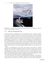
Otherwise the raised quarterdeck is treated as a poop of less than standard
height.