ALUMINIUM ALLOYS NEW TRENDS IN FABRICATION AND APPLICATIONS_2 pptx
Bạn đang xem bản rút gọn của tài liệu. Xem và tải ngay bản đầy đủ của tài liệu tại đây (10.03 MB, 108 trang )
Section 3
Heat Treatment and Welding
Chapter 10
Pure 7000 Alloys: Microstructure,
Heat Treatments and Hot Working
P. Leo and E. Cerri
Additional information is available at the end of the chapter
/>1. Introduction
7000 alloys are used above all in automotive industry and architectural applications. These
materials exhibit medium strength and ductility at room temperature and can be strength‐
ened by aging treatment. Moreover they are characterized by low quench sensitivity, good
corrosion resistance (due to the absence of Cu addition) and good extrudability (higher than
6061 alloy) [1-5].
Because of their commercial importance, much effort has been spent on investigation of the
precipitation process in Al–Zn–Mg alloys [6-10]. The high strength exhibited in the hard‐
ened state is due to a fine distributions of precipitates, notably of the metastable η’ phase
MgZn
2
, produced by artificial aging from a supersaturated solid solution. The temperature
of artificial aging influences the kinetics and the sequence of precipitation and if heterogene‐
ous nucleation of the equilibrium phase appears, a less efficient hardening is obtained. In
this study the response to artificial aging with and without previous solution treatment has
been analyzed in the range of 130°C-210°C in order to evaluate which effect on hardening is
due to the absence of supersaturation of vacancy rich cluster (VRC) and alloying elements
coming from a solution heat treatment and rapid quenching.
There is strong academic and industrial interest in recrystallization driven by the need to
understand and control this phenomenon in order to optimize properties through the care‐
ful control of thermomechanical processing schedules [11]. In this paper, the effects of differ‐
ent heat treatments and Zr content on rate of recrystallization induced by annealing heat
treatment after RT deformation and on further deformation in terms of strain hardening rate
(SHR= dσ/dε), have been analyzed. Recrystallization due to hot deformation by torsion and
tension test at 200°C-500°C and 10
-5
s
-1
-10
-3
s
-1
has been investigated too. During hot working
the Al-Zn-Mg alloys exhibit lower flow stress and higher ductility than Al-Mg alloy (for ex‐
© 2012 Leo and Cerri; licensee InTech. This is an open access article distributed under the terms of the
Creative Commons Attribution License ( which permits
unrestricted use, distribution, and reproduction in any medium, provided the original work is properly cited.
ample 5182 and 5083) [12,13]. Generally dynamic recovery (DRV) is the sole restoration
mechanism in Al alloys [14-17] developing a subgrain structure inside elongated grain. As a
consequence, the flow curves (stress vs strain; σ vs ε) exhibit SH to a steady state regime,
although adiabatic heating may cause a peak and a gradual softening particularly at high
strain rate (έ) and low temperature (T). Ductility is usually high because DRV softened
grains allow accommodation of differential grain boundary (GB) sliding, slowing crack for‐
mation [18-22]. Solutes, in the form of atmospheres hinder dislocation glide reducing DRV
and ductility and raising the flow stress [21-23]. Moreover fine dispersoids pin dislocations
and reduce DRV [24,25]. Precipitation hardening alloys may present varied behaviours as a
result of changes in precipitate morphology. Growth of precipitates during hot working
leads to good ductility and lower stress as shown for Al-Mg-Si [26,27], Al-Cu-Mg [28,29] and
Al-Zn-Mg-Cu [30,31]. Solution treated alloy can exhibit high peak stress and dislocation
density due to dynamic precipitation (DPN), followed by rapid softening as particles coa‐
lesce [29-33]. In this paper the microstructure of hot deformed Al-Zn-Mg samples (even
modified with Zr) both by torsion and tension test have been analyzed by SEM and optical
microscopy in order to justify the stress-strain curve shape.
Hot working of many engineering alloys is often accompanied by the formation of internal
cavities [34-38]. The cavitation process depends strongly on alloy composition and micro‐
structure as well as on the imposed processing condition [3 4 36 37 39]. Particularly large
particles and inclusions, notably on GB, introduce new sources of fissure nucleation lower‐
ing ductility; solidification segregation and low melting constituents, especially if they
spread along the GB, create severe problems [39]. Such cavitation may lead to premature
failure (i.e. failure at strains lower than those expected based on material properties such as
the strain rate sensitivity index and the strain hardening exponent) or result in a finished
part with degraded mechanical properties. The cavitation process comprises three distinct
stages, which in most cases occur simultaneously, i.e., (i) cavity nucleation, (ii) cavity
growth, and (iii) cavity coalescence. Cavities, which usually nucleate preferentially at GB,
triple points, or second-phase particles, grow by either plasticity- or diffusion-controlled
mechanisms, or a combination of the two [35,37,39]. For a given material, the particular
mechanism varies with the imposed deformation conditions.
2. Experimental procedures
The compositions of the alloys studied in this investigation are reported in Table1.
In order to distinguish easily the two materials with regard to Zr content they have been
designated respectively as 7000 and 7000Zr. The materials were supplied in the form of
DC cast billet of 20 cm in diameter and 40 cm in length. Cylindrical samples with gage
length of 13 mm and 5mm diameter were cut parallel to the longitudinal axis of the billet
for tensile and torsion tests. From the same billet, cube samples of 10 mm edges were cut
for heat treatments. Artificial aging has been carried out at 130°C, 160°C, 190°C and 210°C
up to 432h on the as-cast samples and 48h and solutionized ones (2h at 490°C). The ef‐
Aluminium Alloys256
fects of heat treatments were analyzed by hardness (HRF) and electrical conductivity
curves.
Zn Mg Fe Si Ti Zr
7000 5.5 1.2 0.07 0.03 0.01
7000Zr 5.6 1.2 0.07 0.03 0.01 0.16
Table 1. Composition of the alloys (wt%)
The microstructure of as-received alloys has been investigated by optical microscope (Ni‐
kon Epiphot 200) and Scanning Electron Microscope - Focused Ion Beam (SEM FIB) ZEISS
1540. The chemical composition of the matrix and particles was investigated by Energy-
dispersive X-ray spectroscopy (EDS) analysis. For polarized light observation the samples
were ground according to standard methods, electropolished (80ml perchloric acid, 120ml
distilled water, 800ml ethanol, 20V) and anodized (Barker’s reagent). The average grain
size has been evaluated on a population of at least 200 grains by using the NIS software
for imaging analysis.
RT tensile tests were performed on as-cast, solutionized (490°C-2h) and peak aged
(490°C-2h + 160°C-24h) samples and SHR plotted versus (σ-σy). One half of each frac‐
tured sample coming from an RT tensile test was ground parallel to longitudinal axis up
to the middle plane and annealed at 500°C for 3h. After 1,5 h of annealing, the sample
was water quenched and the average grain size calculated in a fixed area close to the frac‐
ture by using the LUCIA G software. Then a second step of annealing at the same temper‐
ature and time (total 3h) was applied to each sample in order to follow the
recrystallization behaviour.
Hot tensile tests have been performed on as-cast alloys in the range 250°C-400°C and
10
-5
to 10
-3
s
-1
. The temperature was measured by two independent thermocouples placed
close to the sample. The true stress-true strain curves were calculated from recorded load-
displacement data according to the usual formula. Hot torsion tests have been performed
in the range 250°C-500°C and 10
-2
to 5s
-1
. The torque and surface strain have been trans‐
formed into equivalent stress and strain by the traditional means. One half of each frac‐
tured sample coming from hot deformation tests were ground parallel to longitudinal axis
up to the mid- plane in order to investigate on both recrystallization (RX) and cavitation
phenomena by optical and SEM analysis. Particularly, for cavitation analysis, micrographs
at 20× have been taken along the length of each metallographic section ( up to 4mm by
fracture mid line) and collected into a montage [Fig.15 a,b,c]. The area of cavities inside
the area of metallographic section (4mm by fracture mid line) and the same area of metal‐
lographic section has been evaluated using NIS software. Cavity area fractions Cs (%)
(area of cavities divided by the area of metallographic section) were determined. Assum‐
Pure 7000 Alloys: Microstructure, Heat Treatments and Hot Working
/>257
ing that cavities are randomly distributed inside the specimen, it has been shown that the
area fraction is equal to volume fraction Cv (%) [30].
3. Results and discussion
The microstructures of as received alloys exhibit interdendritic segregation (Fig.1). In 7000
alloy (Fig 1a) the addition of small amount of Ti produces grain refining because the Al
3
Ti
particles act as nucleation sites and moreover lead to smaller precipitate free zones (PFZ)
and finer grain boundary precipitation [43,44]. In 7000 Zr alloy (Fig 1b) the average grain
size is higher compared to that of 7000 alloy (210±60 μm vs 145±40 μm). It is suggested that
Zr reacts with Al
3
Ti complex to make it a less potent nucleation site [44]. From SEM/ EDS
analysis (Fig.2) hard insoluble brittle particles FeAl
3
/FeAl
6
type have been detected along
grain boundaries (Fig.2a) and MgZn
2
or Mg
3
Zn
3
Al
3
both along and grain boundaries and in‐
side grains (Fig.2b).
a
b
Figure 1. Optical micrographs of 7000 (a) and 7000Zr (b) alloys (5X) showing that the microstructure of both alloys is
characterized by dendritic microsegregation. Different grain size is evident comparing (a) and (b)
The average values of hardness in the as-cast and solutionized state (490°C-2h) are slightly
higher for 7000Zr alloy (Table 2) despite its grain size being higher. In contrast, the as-cast
7000Zr electrical conductivity is lower (22Ms/m vs 23,5Ms/m) for the higher amount of al‐
loying. As shown in Fig.3 solution heat treatment (490°C-2h) reduce microsegregation and
through dissolving hardening particles the hardness is reduced too (Table 2). EDS analysis
did not find Al-Zn-Mg particles in solutionized alloys while some undissolved FeAl
3
/FeAl
6
type particles were found.
Aluminium Alloys258
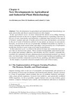
Figure 2:SEM micrograph showing Al/Fe particles (named B, B1) and particles containing Zn and
Mg (named A,A1) (a);EDS spectrum of elements content (b) into the matrix (named C in Fig.2a), and
B1 and A1 particles.
The average values of hardness in the as-cast and solutionized state (490°C-2h) are slightly higher for
7000Zr alloy (Table 2) despite its grain size being higher. In contrast, the as-cast 7000Zr electrical
conductivity is lower (22Ms/m vs 23,5Ms/m) for the higher amount of alloying. As shown in Fig.3
solution heat treatment (490°C-2h) reduce microsegregation and through dissolving hardening
particles the hardness is reduced too (Table 2). EDS analysis did not find Al-Zn-Mg particles in
solutionized alloys while some undissolved FeAl
3
/FeAl
6
type particles were found.
The hardness and electrical conductivity ageing curves performed on solution treated samples (T6
type) and on the as cast samples at 130-210°C are shown in Fig. 4 and Fig. 5 respectively. The aging
treatments (Fig. 4) of solution treated (490°C-2h) samples lead to 15 and 13 point increments of
hardness respectively for 7000 and 7000Zr at the two lowest temperatures of aging. At the higher
temperatures, the precipitation kinetics are faster but the hardening is less efficient due to
heterogeneous nucleations and overaging starts before the peak is reached. Moreover as the VRC are
not retained at high temperature of aging, a lower density of hardening precipitates is expected.
Comparing the behaviour of the two alloys, the response to T6 heat treatment is better at the higher
temperature (190°C and 220°C) for the alloy containing Zr while it is similar for both alloys at the
lower temperature of treatment. This behaviour could be due to Al
3
Zr compounds that don’t dissolve
B
A
C
A1
B1
a
b
0,5 1,0 1,5 2,0 2,5 3,0 3,5 4,0 4,5 5,0 5,5 6,0
0
2500
5000
7500
10000
Zn Mg Al Fe
Al/Fe particles
(
point "B1" in Fig.2a
)
Matrix
(
point "C " in Fig.2a)
0,5 1,0 1,5 2,0 2,5 3,0 3,5 4,0 4,5 5,0 5,5 6,0
0
2500
5000
7500
10000
Counts
Counts
Counts
0,5 1,0 1,5 2,0 2,5 3,0 3,5 4,0 4,5 5,0 5,5 6,0
0
2500
5000
7500
10000
KeV
KeV
Zn/Mg or Al/Zn/Mg particles
(
point "A1" in Fig.2a
)
KeV
Figure 2. SEM micrograph showing Al/Fe particles (named B, B1) and particles containing Zn and Mg (named A,A1)
(a); EDS spectrum of elements content (b) into the matrix (named C in Fig.2a), and B1 and A1 particles.
The hardness and electrical conductivity ageing curves performed on solution treated sam‐
ples (T6 type) and on the as cast samples at 130-210°C are shown in Fig. 4 and Fig. 5 respec‐
tively. The aging treatments (Fig. 4) of solution treated (490°C-2h) samples lead to 15 and 13
point increments of hardness respectively for 7000 and 7000Zr at the two lowest tempera‐
tures of aging. At the higher temperatures, the precipitation kinetics are faster but the hard‐
ening is less efficient due to heterogeneous nucleations and overaging starts before the peak
is reached. Moreover as the VRC are not retained at high temperature of aging, a lower den‐
sity of hardening precipitates is expected. Comparing the behaviour of the two alloys, the
response to T6 heat treatment is better at the higher temperature (190°C and 220°C) for the
alloy containing Zr while it is similar for both alloys at the lower temperature of treatment.
This behaviour could be due to Al
3
Zr compounds that don’t dissolve at high temperature of
treatment and act as nucleation sites for hardening precipitate η’ phase [45-49].The electrical
conductivity increases with temperature of aging and time because of the draining of solute
from the matrix as the precipitation process proceeds. The aging curves of the as cast sam‐
ples (Fig. 5) do not show an increment of hardness with respect to the starting state. The ab‐
sence of super saturation of VRC and alloying elements coming from a solution heat
Pure 7000 Alloys: Microstructure, Heat Treatments and Hot Working
/>259
treatment and rapid quenching, substantially reduces the nucleation of hardening precipi‐
tates. Even for this heat treatment the response of 7000Zr alloy is better at the higher temper‐
ature (190°C and 210°C) compared with the behavior of the alloy without Zr while it is
similar for both alloys at the lower temperature of treatment. The electrical conductivity in‐
creases with temperature of aging and time but it is always lower that in the case of T6 heat
treatment because the lower supersaturation of the matrix.
HRF
As received
HRF
Solutionized
(490°C-2h)
7000 93 86
7000Zr 95 88
Table 2. HRF of as-cast and solutionized 7000 and 7000Zr alloy
b
a
Figure 3. 7000 (a) and 7000Zr(b) alloys after solution heat treatment (490°C-2h). The dissolution of interdendritic seg‐
regation is evident compared to Fig.1
RT tensile tests on as-cast and solutionized samples indicate that solution heat treatment
lead to low peak stress and high ductility (Fig.6) due to dissolution of both brittle phases
and hardening particles. Moreover, the RT ductility is always higher for 7000Zr alloy. In
term of SHR (Fig.7), it is always higher for the alloy in the as-cast state compared to solu‐
tionized because of large uncuttable particles cause Orowan hardening. Moreover 7000Zr al‐
loy exhibits higher SHR probably due to the interaction of Al
3
Zr particles with dislocations.
One half of each fractured samples was ground parallel to the longitudinal axis down to the
mid plane and annealed at 500°C. After 1,5 h of annealing, the samples were water
quenched and analyzed by optical microscopy for checking any recrystallization phenom‐
Aluminium Alloys260
ena. Then, a second step of annealing of 1,5h was applied to each sample (total 3h). Fig. 8 an
Fig.9 illustrate the anodized microstructure of respectively 7000 and 7000Zr specimen as ten‐
sile tested (first line) and 3 hours annealed (second line). The first column presents pictures
from the as cast sample, the second from the solution treated. Annealing treatment lead to
recrystallization rate that is faster on as- cast alloys compared to the solutionized. This result
can be clarified by considering that dissolved atoms and fine precipitates formed in the ma‐
trix limit the movement of dislocation during annealing and delay the nucleation and
growth of new grains. The as cast alloy exhibits both the highest strain hardening rate and
low dissolved atoms; both these aspects lead to a shorter recrystallization time. However as
shown in Fig.9 the recrystallization of 7000Zr alloy is incomplete and not homogeneous
even after three hours of annealing because of additions of Zr.
Figure 4. Hardness and electrical conductivity of 7000 and 7000Zr alloys during aging at 130°C, 160°C, 190°C and
210°C after solution treatment at 490°C-2h (initial value at 0,1min).
The peak stress σ
p
decreases with increasing T at constant έ; moreover, it decreases with de‐
creasing έ at a fixed temperature [Fig. 10]. For each fixed temperature T, the ductility decreas‐
es as έ increases for 7000 alloy deformed by torsion and tension test while rises with έ for 7000
Zr tensile samples. This behavior being more evident with increasing temperature is common
in creep [51,52]. In contrast for hot working as έ decreases, ductilities increases since the im‐
proved DRV mitigates stress concentration and nucleation of voids (usually at triple junc‐
Pure 7000 Alloys: Microstructure, Heat Treatments and Hot Working
/>261
tions). Moreover, at fixed έ, as T increases, recovery is improved and therefore ductility
increases. Ductility in torsion is always higher than in tension because the low normal to shear
stress ratio enhances the role of DRV in inhibiting cracking [39]. The peak values are always
higher in torsion because the higher έ involved. Constitutive analysis for torsion test gave a Q
value of 161Kj/mol [1]. The value of Q close to that of pure Al is due to precipitated particles
that are inefficient in interacting with dislocations as confirmed by the low declines in the
flow curves and by the very low value of average n (1,5)[1]. In fact the microstructure of as-
cast samples hot torsioned at temperature higher than 300°C exhibits significant precipitated
particles. Their number decrease as T increases do to overaging or cooperative growth of par‐
ticles and/or to their dissolution while at fixed T increases with strain rate due to strain hard‐
ening effect on enhancing precipitation kinetics (Fig. 11). Optical analysis of torsioned
samples on longitudinal plane close to fracture surface after chemical etchant (Keller) shows
that only the samples deformed at 500°C exhibit recrystallized grains from SRX (Fig. 12). At
400°C the microstructure is characterized mainly by subgrain as is evident from anodized lon‐
gitudinal plane of Fig.13. Subgrain have been observed in grains at 300°C 0.1s
-1
and 0.01 s
-1
too. Even the samples deformed by tensile at 350°C-400°C show some SRX ( Fig.14). Static re‐
crystallization is much more evident in the alloy without Zr, close to the fracture surface and
near grain boundaries and due to stress localization (Fig.14).
Figure 5. Hardness and electrical conductivity of as-cast 7000 and 7000Zr alloys during aging at 130°C, 160°C, 190°C
and 210°C (initial value at 0,1min).
Aluminium Alloys262
The microstructure of tensioned samples is characterized by cavitation (Fig.15) phenomena.
Cavitation is much more evident in the alloy without Zr ( Fig.15 b) and it is strongly re‐
duced only if the alloy is solutionized (490°C-2h) before tensile test (Fig.15c). In fact this phe‐
nomena is mainly due to both segregation and stress concentration at particles (Fig.15d).
Solution heat treatment reduce microsegregation (Fig.3) and dissolve soluble Mg-Zn parti‐
cles, leading therefore to a reduction of the both hardness and cavitation. Some brittle parti‐
cles (for example FeAl
3
/ FeAl
6
in Fig.2) are not dissolved from solution heat treatment and
continue to act as cavity nucleation point.
Cavitation (Cs%) Vs strain rate is shown in Fig.16 for as the cast 7000 sample deformed at
250°C and 400°C. Cavitation increases with T and, at fixed T it increases as strain rate decreas‐
es. The distribution of cavities along the longitudinal sample surfaces at 250°C and 400°C is
shown in Fig. 17. At the lowest T, cavitation values decrease as distance from fracture increas‐
es while at 400°C the cavities are randomly distributed along the longitudinal area of the sam‐
ples. So it can be assumed a more active role of grain boundaries sliding (GBS) on cavitation
nucleation and growth at the highest T. Theoretical modelling on cavitation in general takes
into account the three distinct stages of damage generation, i.e. nucleation, growth and coales‐
cence [40], but, among these, the growth appears the critical phase [41].
a
b
Figure 6. Room temperature tensile curves for 7000 (a) and 7000Zr samples (b) in the following conditions: as cast
and solution treated 490°C-2h
Pure 7000 Alloys: Microstructure, Heat Treatments and Hot Working
/>263
a
b
Figure 7. Strain hardening rate curves for the RT tensile curves of 7000 (a) and 7000Zr (b) alloy in the as-cast and solu‐
tionized state.
a
b
c
d
Figure 8. Optical micrographs of 7000 tensioned specimens before (a,b) and after 3h of annealing at 500°C (c,d)
where (a,c) are as cast, (b,d) are solution treated
a
c
b
d
Figure 9. Optical micrographs of 7000Zr tensioned specimens before (a,b) and after 3h of annealing at 500°C (c,d)
where (a,c) are as-cast, (b,d) are solution treated.
Aluminium Alloys264
250 300 350 400
0,0
0,2
0,4
0,6
0,8
1,0
10
-3
s
-1
10
-4
s
-1
10
-5
s
-1
Failure strain
e
f
Temperature [°C]
d
150 200 250 300 350 400 450 500 550
0
2
4
6
8
10
e
10
-2
s
-1
10
-1
s
-1
1s
-1
5s
-1
Temperature [°C]
Failure strain
e
f
250 300 350 400
0,0
0,2
0,4
0,6
0,8
1,0
f
10
-3
s
-1
10
-4
s
-1
10
-5
s
-1
Failure strain
e
f
Temperature(°C)
250 300 350 400
0
20
40
60
80
100
120
140
160
a
Stress (MPa)
Temperature (°C)
10
-3
s
-1
10
-4
s
-1
10
-5
s
-1
150 200 250 300 350 400 450 500 550
0
50
100
150
200
250
b
Temperature (°C)
Stress (MPa)
10
-2
s
-1
10
-1
s
-1
1s
-1
5s
-1
250 300 350 400
0
20
40
60
80
100
120
140
160
c
10
-3
s
-1
10
-4
s
-1
10
-5
s
-1
Stress (MPa)
Temperature(°C)
Figure 10. Peak stress variations (a,b,c) and failure stress (d,e,f) as a function of T for the as-cast 7000 alloy hot de‐
formed by tension (a,d) and by torsion (b,e) and for 7000 Zr alloy hot deformed by tension (c,f).
c
a
b
Figure 11. Precipitated particles in hot torsioned samples at 300°C-0,1s
-1
(a), 300°C-0,01s
-1
(b) and 400°C-0,1s
-1
(c): at
fixed T (a,b) the number of particles increases with strain rate due to enhanced precipitation on dislocations, while as
T increases the size of particles increase due to overaging (a,c).
Pure 7000 Alloys: Microstructure, Heat Treatments and Hot Working
/>265
Figure 12. Optical micrographs (50X) of torsioned samples on longitudinal planes close to fracture surface after Keller
etchant showing that only the samples deformed at the highest T exhibit SRX.
Figure 13. Optical micrographs (20X) of torsioned samples on longitudinal planes close to fracture surface after anod‐
izing showing that the microstructure at 400°C and is characterized mainly by subgrains. Subgrains have been ob‐
served in some grains at 300°C and 0.1 s
-1
-0.01s
-1
Aluminium Alloys266
Figure 14. SRX close to fracture surface of hot deformed tensile test 7000 alloy at 400°C-10
-4
s
-1
with Zr (a) and with‐
out (b)
c
d
Figure 15. Optical micrographs of cavitation phenomena in as-cast 7000 (a), 7000Zr (b), solutionized 7000 alloys (c)
deformed by tensile test at 350°C 10
-4
s
-1
. SEM micrographs of 7000 as-cast alloy (d) showing that cavities originate at
brittle particles.
When cavity growth is controlled by plastic deformation, the simplest model for cavity
growth assumes the following form [38]:
( )
exp
0
CC
v
he
=
(1)
Pure 7000 Alloys: Microstructure, Heat Treatments and Hot Working
/>267
where C
0
is the initial volume fraction of cavities and ε is the fracture strain. Following Lee
and Huang [40], who based their analysis on the Stowell et al. relationship [41], one can ex‐
press the cavity growth exponent as follows [42]:
(
)
(
)
22
1
3
sinh
32
2
m
m
mm
h
éù
æö
-
+
êú
ç÷
=
êú
ç÷
ç÷
+
êú
èø
ëû
(2)
Where m is the strain rate sensitivity of flow stress.
Figure 16. Cavitation (Cs%) versus log strain rate showing that the area of fissures increases with T and, at the highest
T, with decreasing strain rate
Figure 17. Cavitation (Cs%) versus distance from fracture at 250°C (a) and 400°C (b) showing that at the lowest T the
area of fissures decrease as distance from fracture increases while at 400°C cavities are randomly distributed along the
longitudinal area of the samples.
When the fracture strain is substituted into Eqn.1, an obvious approximation, since the frac‐
ture strain is affected by necking, the plot presented (with C
0
arbitrarily assumed to be
Aluminium Alloys268
0.03%) in Fig. 18 are obtained. Although this calculation is based on very rough assump‐
tions, the model of cavity growth controlled by plastic strain describes very well the ob‐
served cavitation trend. It can be thus reasonably concluded that, in the investigated range
of experimental conditions, the cavity growth is mainly driven by plastic straining. GBS sub‐
stantially contributes to enhance the fraction of cavities at the highest T and justifies the ob‐
served difference between the calculated value and experimental one (Fig.18).
Figure 18. Comparison of measured Cs% and calculated Cv% versus log strain rate at 250°C and 400°C
4. Conclusions
The main conclusions are summarized in the following :
• In the as received state the grain size of 7000 Zr alloy is larger than that of 7000 alloy due
to reaction between Zr and Ti that reduce the nucleation power of both elements and the
microstructure of both alloys is characterized by dendritic microsegregation. The solution
heat treatment at 490°C-2h leads to a strong reduction of segregation and to a complete
dissolution of hardening Al-Zn-Mg particles as shown by EDS analysis. As consequence
the hardness decreases. For the larger grain size and higher amount of alloying the electri‐
cal conductivity of 7000Zr is always lower than that of 7000 alloy.
• The response to heat treatment for both the as cast and solutionized samples is better at
the higher temperature (190°C and 210°C) for the alloy containing Zr, while it is similar
for both alloys at the lower temperature of treatment. This behaviour could be due to
Al
3
Zr compounds that don’t solutionize at high temperature of treatment and moreover,
harden the alloy and can act as nucleation sites for hardening precipitate η’ phase. Aging
treatment of the as-cast alloys for the range of imposed times is ineffective in terms of in‐
creasing hardness.
Pure 7000 Alloys: Microstructure, Heat Treatments and Hot Working
/>269
• Concerning RT tensile tests, the SHR is higher for the as cast sample comparing to the sol‐
utionized. As consequence the recrystallization rate of as cast sample is faster too. Due to
Zr effect it is incomplete and not homogeneous in the Zr modified alloy.
• During hot tensile test the as cast alloys exhibit high flow stress at low temperature due to
reduced DRV. At higher T, both improved DRV and overaging of particles lead to re‐
duced peak stress. The phenomena is much more evident during torsion because of T in‐
volved. For each fixed temperature T, the ductility decreases as έ increases for 7000 alloy
deformed by torsion and tension while rises with έ for 7000 Zr tensile samples.
• The microstructure of both torsion and tensile samples hot deformed at the highest tem‐
peratures exhibit some SRX, more evident in the alloy without Zr.
• Cavitation in 7000 hot tensioned samples increases with T and with decreasing strain rate.
At the lowest T, 7000 as cast alloy cavitation decreases as distance from fracture surface
increases while at the highest T cavities are randomly distributed along longitudinal sur‐
face of samples, suggesting a more active role of GBS on cavitation nucleation and
growth. Theoretical calculation have shown that cavity growth is mainly driven by plastic
straining but GBS substantially contributes to enhance the fraction of cavities and justify
the observed difference between the calculated and experimental cavitation values at the
highest T and lowest strain rate. Cavitation is reduced if the alloy is solutionized before
deformation.
Author details
P. Leo
*
and E. Cerri
Università del Salento, via per Arnesano, Lecce, Italy
References
[1] H.J. McQueen, P. Leo and E. Cerri; Aluminum Alloys: Fabrication, Characterization
and Applications, : Weimin Yin, Subodh Das, Zhengdong Long Eds: TMS USA 2009
pp.37-44
[2] J.E. Hatch,ed. Aluminum, Properties, Physical Metallurgy, ASM, Metals Park, Oh,
1984
[3] H.J.McQueen, O.C. Celliers, Canadian Metal. Quart. 36 (1997), 73-86
[4] K. Laue, H.Stenger, Extrusion: Process Machinery, Tooling, American Society for
Metals, Metals Park, OH (1981), 1-62; 124-152
[5] Y.Baba, H.Yoshido, Proc. 2nd Intnl.Al. Exrusion Tech. Sem., Aluminium Association,
Washington, (1997) Vol. 1, 301-306
Aluminium Alloys270
[6] T. Engdahl, V. Hansen, P.J. Warren, K. Stiller , Mater. Sci. Eng. A 327, (2002), 59
[7] K. Stiller, P.J.Warren, V. Hansen, J. Angenete, J. Gjonnes, Mater. Sci. Eng. A270,
(1999),55
[8] S.K. Maloney, K. Hono, I.J. Polmear, S.P. Ringer, Scripta Mater. 41, 10, (1999), 1031
[9] H.Z.Li, V. Hansen, J. Jonnes, L. R. Wallenberg, Acta Mater. 47, 9. (1999), 2651
[10] J.C. Werwnskiold, A. Deschemps, Y. Bréchet, Mater.Sci. Eng. A293, (2000), 267
[11] M.J. Jones , F.J. Humphreys, Acta Mater. 51 (2003) 2149–2159
[12] H.J. McQueen, N.Owen, Materials in Automotive Industry E.Essadigi et al., Eds.,
Mat.Soc.Cim, Montreal (2001), pp.189-205
[13] W. Blum, H.J. McQueen, Aluminum Alloys, Physical Mechanical Properties, ICAA5
Mater. Sci. Forum 217-222,(1996), pp. 31-42
[14] H.J. McQueen, W. Blum. Aluminium Alloys, Phisical and Mechanical Properties
ICAA6,T.Sato, ed Japan Inst. Metals (1998), pp. 99-112
[15] R.D.Doherty et al. Mat. Sci. Eng. A 238, 2 (1997) pp.219-274
[16] M. El Mehtedi, S. Spigarelli, E Evangelista, La metallurgia italiana, (September 2007)
pp. 21-28
[17] H.J. McQueen, in Advanced Materials for 21st Century, J.R. Weertman Symp, Y.P.
Chung Ed, TMS-AIME, Warrendale, PA, (1999), pp. 159-168
[18] S. Fulop , K.C. Cadien, M.J. Luton, H.J. McQueen, J. Test Eval. 5 (1977) pp.419-426
[19] N.D. Ryan, H.J. McQueen, J. Mech. Working Tech. 12 (1986) pp. 279-296
[20] C.M. Sellars, W.J. McG. Tegart, Int. Metall. Rev. 17 (1972) pp. 1-24
[21] H.J. McQueen in Hot deformation of Aluminum alloys, T.G. Langdon, H.D.Mer‐
chant, J.G.Morris and M.A.Zaidi Eds, Warrendale, PA, 1990, pp. 31-54.
[22] H.J. McQueen and J.J. Jonas in C.Q. Chen et al (eds.), Aluminum alloys 90 (Icaa2) Bei‐
jing, 1990, pp.727-742
[23] H.J. McQueen and K.Conrod in Microstructural control in Aluminum alloys, E.H.
Chia and H.J. McQueen (Eds), TMS-AIME, Warrendale, PA, 1986, pp.197-219
[24] H.J. McQueen, E. Evangelista, J. Bowles and G. Crawford, Met Sci. 18, (1984), p.
395-402
[25] E. Evangelista, H.J. McQueen and E. Bonetti in Deformation of Multi-phase and par‐
ticles containing Materials, J.B. Bildensoren et al (eds), Riso National Laboratory,
Roskilde, 1983, pp.243-250
[26] H.J. McQueen in Hot deformation of Aluminum alloys, T.G. Langdon, H.D.Mer‐
chant, J.G.Morris and M.A.Zaidi (eds), Warrendale, PA, 1990, pp. 105-120
Pure 7000 Alloys: Microstructure, Heat Treatments and Hot Working
/>271
[27] E.Evangelista, A.Forcellese, F. Gabrielli and P.Mengucci in Hot deformation of Alu‐
minum alloys, T.G. Langdon, H.D.Merchant, J.G.Morris and M.A.Zaidi (eds),War‐
rendale, PA, 1990, pp. 121-139
[28] B. Verlinden, P.Wouters, H.J. McQueen, E. Aernoudt, L.Delaey and S. Cauwemberg,
Mat.Sci.Eng.A, 123 (1990) pp.229-237
[29] P.Wouters, B. Verlinden, H.J. McQueen and E. Aernoudt, Mat.Sci.Eng.A, 123 (1990)
pp.239-245
[30] E. Evangelista, E. Di Russo, H.J. McQueen and P. Mengucci in Homogenization and
Annealing of Al and Cu Alloys, H.D. Merchant, J. Crane and E.H. Chia (eds.), TMS-
AIME Warrendale, PA, 1988, p. 209
[31] H.J. McQueen, E. Evangelista, A.Forcellese, I.C. Smith and E. Di Russo, in Modelling
the deformation of Crystalline Solids, T.C. Lowe, A.D. Rollet, P.S. Follanbee and G.S.
Daehn (eds.), TMS-AIME, Warrendale, PA, 1991, p.281-292
[32] A. Espedal, H. Gjestland, N. Ryum and H.J. McQueen, Scand J. Met. 18 ,1989, pp.
131-136
[33] E. Evangelista, H.J. McQueen and E. Cerri, , Modelling of plastic deformation and its
Engineering Applications, S.I. Andersen et al. eds, Riso National Laboratory, Ros‐
kilde, DK, 1992, pp. 265-270
[34] P.A.Friedman and W.B.Copple, Proceeding of TMS,2003,Hot deformation of alumi‐
num alloy III 211-219
[35] D. Nicolau, S.L. Semiantin, Acta Mat. 51, (2003) 613-623
[36] E.M. Taleff, P.J. Nevland and P. Krajewski, Metall.Mater.Trans. 32A (2001) 1119-1130.
[37] M.F.Ashby, C. Gandhi and D.M.R. Taplin, Acta Metall. 27 (1979) 699-729.
[38] M.J. Stowell, Cavitation in Superplasticity, in “Superplastic forming of structural al‐
loys”, N.E. Paton and C.H. Hamilton Eds., TMS-AIME, Warrendale, PA, 1982,
321-326
[39] H.J.McQueen, Materials Science Forum.Vols. 604-605 (2009)
[40] X G. Jiang, J.C. Erathman and F.A.Mohamed, J.Mater.Sci. 29 (1994) 5499-5514.
[41] C.J.Lee and J.C.Huang, Acta Mater. 52 (2004) 3111-3122.
[42] M.J.Stowell, D.W.Livesey and N.Ridley, Acta Metall. 32 (1984) 35-42.
[43] J. Polmear Light alloys –Metallurgy of light metals, Butterworth Heinemann 1995,
115-118
[44] Bjorn Ronning, Thesis “ Constitutive relationships for AlZnMg, AlZnMgCr and
AlZnMgZr alloys” October 1998, University of Trondeim, Norway
Aluminium Alloys272
[45] P. Leo, E. Cerri, H.J. McQueen and S. Chiozzi, Mater. Sci. Forum 604-605; 2009, pp.
67-76
[46] L.K. Berg, G. Gjonnes,V. Hansen et al. Acta Mater, 49, (2001),3493
[47] H. Loffer, I. Kovacs, J. Lendvai, J. Mater. Sci. 18, (1983), 2215
[48] Z. Katz, N.Ryum, Scripta Met. 15, (1981), 265
[49] J.D.Verhoeven, “Fundamental of Physical Metallurgy” J. Wiley e Sons, NY (1975),
Chapter 6,
[50] P.Leo, E. Cerri, H.McQueen and A.Taurino, ICA11, in ‘Aluminium Alloys – Their
Physical and Mechanical Properties’ J. Hirsch, B. Skrotzki and G. Gottstein eds,Wi‐
ley-VCH (DE) 2008, pp. 1868-1874.
[51] M.E. Kassner, M.T. Perez-Prado, Fondamental of creep in metals and alloys, Elsivier
2004, 1-15
[52] R.W. Evans, B. Wilshire, Introduction to creep, Oakdale Printing Company Ltd, 1993,
16-22
Pure 7000 Alloys: Microstructure, Heat Treatments and Hot Working
/>273
Section 4
Durability, Degradation and Recycling of
Aluminium Alloys
Chapter 11
Mechanical and Metalurgical Properties of Friction
Welded Aluminium Joints
Mumin Sahin and Cenk Misirli
Additional information is available at the end of the chapter
/>1. Introduction
Aluminium alloys are alloys in which aluminium (Al) is the predominant metal. The typical
alloying elements are copper, magnesium, manganese, silicon and zinc. There are two prin‐
cipal classifications, namely casting alloys and wrought alloys, both of which are further
subdivided into the categories heat-treatable and non-heat-treatable. About 85% of alumini‐
um is used for wrought products, for example rolled plate, foils and extrusions. Cast alumi‐
nium alloys yield cost effective products due to the low melting point, although they
generally have lower tensile strengths than wrought alloys. The most important cast alumi‐
nium alloy system is Al-Si, where the high levels of silicon (4.0% to 13%) contribute to give
good casting characteristics. Aluminium alloys are widely used in engineering structures
and components where light weight or corrosion resistance is required [1].
Light non-ferrous metals such as aluminium and magnesium alloys have drawn attention
with regard to application due to their energy-saving character. Above all, aluminium alloys
are used more due to their superior workability and less cost. However, they are not entirely
replaced by stainless steel, stainless steel having superior strength and weldability in certain
structures. Therefore, it is necessary to join stainless steel and aluminium materials. Then,
copper - aluminium joints are inevitable for certain applications due to unique performances
such as higher electric conductivity, heat conductivity, corrosion resistance and mechanical
properties. Aluminium and copper are replacing steels in electricity supply systems due to
higher electric conductivity.
Friction welding is used extensively in various industries. Heat in friction welding is gener‐
ated by conversion of mechanical energy into thermal energy at the interface of work pieces
during rotation under pressure. Various ferrous and non-ferrous alloys having circular or
non-circular cross sections and that have different thermal and mechanical properties can
© 2012 Sahin and Misirli; licensee InTech. This is an open access article distributed under the terms of the
Creative Commons Attribution License ( which permits
unrestricted use, distribution, and reproduction in any medium, provided the original work is properly cited.