TU petrol engine in-car repair procedures (Part A) potx
Bạn đang xem bản rút gọn của tài liệu. Xem và tải ngay bản đầy đủ của tài liệu tại đây (415.48 KB, 14 trang )
2A
Engine (general)
Designation . . . . . . . . . . . . . . . . . . . . . . . . . . . . . . . . . . . . . . . . . . . . . . . TU3
Engine code:
UK models (10/92 to 08/93) . . . . . . . . . . . . . . . . . . . . . . . . . . . . . . . . KDX (TU3MC/L/Z)
Non-UK models (07/87 to 06/88) . . . . . . . . . . . . . . . . . . . . . . . . . . . . K1A (TU3)
Non-UK models (07/88-on) . . . . . . . . . . . . . . . . . . . . . . . . . . . . . . . . . K1G (TU3A)
Non-UK models (11/87-on) . . . . . . . . . . . . . . . . . . . . . . . . . . . . . . . . . K3A (TU3TR)
Non-UK models (1993-on) . . . . . . . . . . . . . . . . . . . . . . . . . . . . . . . . . K2D (TU3F2/K)
Capacity . . . . . . . . . . . . . . . . . . . . . . . . . . . . . . . . . . . . . . . . . . . . . . . . . 1360 cc
Bore . . . . . . . . . . . . . . . . . . . . . . . . . . . . . . . . . . . . . . . . . . . . . . . . . 75.00 mm
Stroke . . . . . . . . . . . . . . . . . . . . . . . . . . . . . . . . . . . . . . . . . . . . . . . . . 77.00 mm
Direction of crankshaft rotation . . . . . . . . . . . . . . . . . . . . . . . . . . . . . . . Clockwise (viewed from right-hand side of vehicle)
No 1 cylinder location . . . . . . . . . . . . . . . . . . . . . . . . . . . . . . . . . . . . . . . At transmission end of block
Compression ratio:
Except K3A . . . . . . . . . . . . . . . . . . . . . . . . . . . . . . . . . . . . . . . . . . . . . 9.3 : 1
K3A . . . . . . . . . . . . . . . . . . . . . . . . . . . . . . . . . . . . . . . . . . . . . . . . . 8.3 : 1
*The engine code is situated on the front left-hand end of the cylinder block. It is either stamped on a plate which is riveted to the block
(aluminium block engines) or stamped directly on the cylinder block (cast-iron block engines). The code given in brackets is the factory identifi-
cation number, and is not often referred to by this manual.
Camshaft
Drive . . . . . . . . . . . . . . . . . . . . . . . . . . . . . . . . . . . . . . . . . . . . . . . . . Toothed belt
Number of bearings . . . . . . . . . . . . . . . . . . . . . . . . . . . . . . . . . . . . . . . . 5
Camshaft bearing journal diameter (outside diameter):
No 1 . . . . . . . . . . . . . . . . . . . . . . . . . . . . . . . . . . . . . . . . . . . . . . . . . 36.950 to 36.925 mm
No 2 . . . . . . . . . . . . . . . . . . . . . . . . . . . . . . . . . . . . . . . . . . . . . . . . . 40.650 to 40.625 mm
No 3 . . . . . . . . . . . . . . . . . . . . . . . . . . . . . . . . . . . . . . . . . . . . . . . . . 41.250 to 41.225 mm
No 4 . . . . . . . . . . . . . . . . . . . . . . . . . . . . . . . . . . . . . . . . . . . . . . . . . 41.850 to 41.825 mm
No 5 . . . . . . . . . . . . . . . . . . . . . . . . . . . . . . . . . . . . . . . . . . . . . . . . . 42.450 to 42.425 mm
Cylinder head bearing journal diameter (inside diameter):
No 1 . . . . . . . . . . . . . . . . . . . . . . . . . . . . . . . . . . . . . . . . . . . . . . . . . 37.000 to 37.039 mm
No 2 . . . . . . . . . . . . . . . . . . . . . . . . . . . . . . . . . . . . . . . . . . . . . . . . . 40.700 to 47.739 mm
No 3 . . . . . . . . . . . . . . . . . . . . . . . . . . . . . . . . . . . . . . . . . . . . . . . . . 41.300 to 41.339 mm
No 4 . . . . . . . . . . . . . . . . . . . . . . . . . . . . . . . . . . . . . . . . . . . . . . . . . 41.900 to 41.939 mm
No 5 . . . . . . . . . . . . . . . . . . . . . . . . . . . . . . . . . . . . . . . . . . . . . . . . . 42.500 to 42.539 mm
Valve clearances (engine cold)
Inlet . . . . . . . . . . . . . . . . . . . . . . . . . . . . . . . . . . . . . . . . . . . . . . . . . 0.20 mm
Exhaust . . . . . . . . . . . . . . . . . . . . . . . . . . . . . . . . . . . . . . . . . . . . . . . . . 0.40 mm
Chapter 2 Part A:
TU petrol engine in-car repair procedures
Camshaft and rocker arms - removal, inspection and refitting . . . . .10
Camshaft oil seal - renewal . . . . . . . . . . . . . . . . . . . . . . . . . . . . . . . . .8
Compression test . . . . . . . . . . . . . . . . . . . . . . . . . . . . . . . . . . . . . . . . .2
Crankshaft oil seals - renewal . . . . . . . . . . . . . . . . . . . . . . . . . . . . . . .14
Cylinder head - removal and refitting . . . . . . . . . . . . . . . . . . . . . . . . .11
Cylinder head cover - removal and refitting . . . . . . . . . . . . . . . . . . . . .4
Engine assembly/valve timing holes -
general information and usage . . . . . . . . . . . . . . . . . . . . . . . . . . . . .3
Engine oil and filter renewal . . . . . . . . . . . . . . . . . . . . . . .See Chapter 1
Engine oil level check . . . . . . . . . . . . . . . . . . . . . .See “Weekly checks”
Engine/transmission mountings - inspection and renewal . . . . . . . . .16
Flywheel - removal, inspection and refitting . . . . . . . . . . . . . . . . . . . .15
General information . . . . . . . . . . . . . . . . . . . . . . . . . . . . . . . . . . . . . . .1
Oil pump - removal, inspection and refitting . . . . . . . . . . . . . . . . . . .13
Sump - removal and refitting . . . . . . . . . . . . . . . . . . . . . . . . . . . . . . .12
Timing belt - general information, removal and refitting . . . . . . . . . . . .6
Timing belt covers - removal and refitting . . . . . . . . . . . . . . . . . . . . . .5
Timing belt tensioner and sprockets -
removal, inspection and refitting . . . . . . . . . . . . . . . . . . . . . . . . . . .7
Valve clearances - checking and adjustment . . . . . . . . . . . . . . . . . . . .9
2A•1
Easy, suitable for
novice with little
experience
Fairly easy, suitable
for beginner with
some experience
Fairly difficult,
suitable for competent
DIY mechanic
Difficult, suitable for
experienced DIY
mechanic
Very difficult,
suitable for expert
DIY or professional
Degrees of difficulty
Specifications
Contents
Lubrication system
Oil pump type . . . . . . . . . . . . . . . . . . . . . . . . . . . . . . . . . . . . . . . . . . . . . Gear-type, chain-driven off the crankshaft
Minimum oil pressure at 90°C:
Except K2D . . . . . . . . . . . . . . . . . . . . . . . . . . . . . . . . . . . . . . . . . . . . . 4 bars at 4000 rpm
K2D . . . . . . . . . . . . . . . . . . . . . . . . . . . . . . . . . . . . . . . . . . . . . . . . . 3 bars at 2000 rpm
Oil pressure warning switch operating pressure . . . . . . . . . . . . . . . . . . 0.8 bars
Torque wrench settings Nm lbf ft
Cylinder head cover nuts . . . . . . . . . . . . . . . . . . . . . . . . . . . . . . . . . . . . 16 12
Timing belt cover bolts . . . . . . . . . . . . . . . . . . . . . . . . . . . . . . . . . . . . . . 8 6
Crankshaft pulley retaining bolts . . . . . . . . . . . . . . . . . . . . . . . . . . . . . . 8 6
Timing belt tensioner pulley nut . . . . . . . . . . . . . . . . . . . . . . . . . . . . . . . 23 17
Camshaft sprocket retaining bolt . . . . . . . . . . . . . . . . . . . . . . . . . . . . . . 80 59
Crankshaft sprocket retaining bolt . . . . . . . . . . . . . . . . . . . . . . . . . . . . . 110 81
Camshaft thrust fork retaining bolt . . . . . . . . . . . . . . . . . . . . . . . . . . . . . 16 12
Cylinder head bolts (aluminium block engine):
Stage 1 . . . . . . . . . . . . . . . . . . . . . . . . . . . . . . . . . . . . . . . . . . . . . . . . 20 15
Stage 2 . . . . . . . . . . . . . . . . . . . . . . . . . . . . . . . . . . . . . . . . . . . . . . . . Angle-tighten a further 240°
Cylinder head bolts (cast-iron block engine):
Stage 1 . . . . . . . . . . . . . . . . . . . . . . . . . . . . . . . . . . . . . . . . . . . . . . . . 20 15
Stage 2 . . . . . . . . . . . . . . . . . . . . . . . . . . . . . . . . . . . . . . . . . . . . . . . . Angle-tighten a further 120°
Stage 3 . . . . . . . . . . . . . . . . . . . . . . . . . . . . . . . . . . . . . . . . . . . . . . . . Angle-tighten a further 120°
Sump drain plug . . . . . . . . . . . . . . . . . . . . . . . . . . . . . . . . . . . . . . . . . . . 30 22
Sump retaining nuts and bolts . . . . . . . . . . . . . . . . . . . . . . . . . . . . . . . . 8 6
Oil pump retaining bolts . . . . . . . . . . . . . . . . . . . . . . . . . . . . . . . . . . . . . 8 6
Flywheel retaining nuts and bolts . . . . . . . . . . . . . . . . . . . . . . . . . . . . . . 65 48
Piston oil jet spray tube bolts - 1587 cc models . . . . . . . . . . . . . . . . . . 10 7
Big-end bearing cap nuts . . . . . . . . . . . . . . . . . . . . . . . . . . . . . . . . . . . . 40 30
Main bearing ladder casting (aluminium block engine):
11 mm bolts:
Stage 1 . . . . . . . . . . . . . . . . . . . . . . . . . . . . . . . . . . . . . . . . . . . . . . 20 15
Stage 2 . . . . . . . . . . . . . . . . . . . . . . . . . . . . . . . . . . . . . . . . . . . . . . Angle-tighten a further 45°
6 mm bolts . . . . . . . . . . . . . . . . . . . . . . . . . . . . . . . . . . . . . . . . . . . . . 8 6
Main bearing cap bolts (cast-iron block engine):
Stage 1 . . . . . . . . . . . . . . . . . . . . . . . . . . . . . . . . . . . . . . . . . . . . . . . . 20 15
Stage 2 . . . . . . . . . . . . . . . . . . . . . . . . . . . . . . . . . . . . . . . . . . . . . . . . Angle-tighten a further 45°
2A•2 TU engine in-car repair procedures
1 General information
How to use this Chapter
1 This Part of Chapter 2 describes those
repair procedures that can reasonably be
carried out on the TU series engine while it
remains in the car. If the engine has been
removed from the car and is being dismantled
as described in Part C, any preliminary
dismantling procedures can be ignored. Refer
to Part B for the XU series petrol engine.
2 Note that, while it may be possible
physically to overhaul items such as the
piston/connecting rod assemblies while the
engine is in the car, such tasks are not
normally carried out as separate operations.
Usually, several additional procedures (not to
mention the cleaning of components and
oilways) have to be carried out. For this
reason, all such tasks are classed as major
overhaul procedures, and are described in
Part C of this Chapter.
3 Part C describes the removal of the
engine/transmission from the vehicle, and the
full overhaul procedures that can then be
carried out.
TU series engine description
4 The TU series engine is a well-proven
engine which has been fitted to many
previous Peugeot and Citroën vehicles. The
engine is of the in-line four-cylinder, overhead
camshaft (OHC) type, mounted transversely at
the front of the car. The clutch and
transmission are attached to its left-hand end.
The 405 range is fitted with the 1360 cc
version of the engine; carburettor and fuel-
injected versions are available (carburettor
versions not available in the UK).
5 The crankshaft runs in five main bearings.
Thrustwashers are fitted to No 2 main bearing
(upper half) to control crankshaft endfloat.
6 The connecting rods rotate on horizontally-
split bearing shells at their big-ends. The
pistons are attached to the connecting rods
by gudgeon pins, which are an interference fit
in the connecting rod small-end eyes. The
aluminium-alloy pistons are fitted with three
piston rings - two compression rings and an
oil control ring.
7 Where the cylinder block is made of
aluminium, replaceable wet liners are fitted.
Sealing O-rings are fitted at the base of each
liner, to prevent the escape of coolant into the
sump.
8 Where the cylinder block is made from cast
iron, the cylinder bores are an integral part of
the cylinder block. On this type of engine the
cylinder bores are sometimes referred to as
having dry liners.
9 The inlet and exhaust valves are each
closed by coil springs, and operate in guides
pressed into the cylinder head; the valve seat
inserts are also pressed into the cylinder
head, and can be renewed separately if worn.
10 The camshaft is driven by a toothed
timing belt, and operates the eight valves via
rocker arms. Valve clearances are adjusted by
a screw-and-locknut arrangement. The
camshaft rotates directly in the cylinder head.
The timing belt also drives the coolant pump.
11 Lubrication is by means of an oil pump,
which is driven (via a chain and sprocket) off
the right-hand end of the crankshaft. It draws
oil through a strainer located in the sump, and
then forces it through an externally-mounted
filter into galleries in the cylinder
block/crankcase. From there, the oil is
distributed to the crankshaft (main bearings)
and camshaft. The big-end bearings are
supplied with oil via internal drillings in the
crankshaft, while the camshaft bearings also
receive a pressurised supply. The camshaft
lobes and valves are lubricated by splash, as
are all other engine components.
12 Throughout this manual, it is often
necessary to identify the engines not only by
their capacity, but also by their engine code
which can be found on the left-hand end of
the front face of the cylinder block. On models
with an aluminium cylinder block the code is
stamped on a plate which is riveted to the
block, and on models with a cast iron cylinder
block the number is stamped on a machined
surface on the cylinder block, at the flywheel
end. The first part of the engine number gives
the engine code - eg “KDX” (see illustration).
Repair operations possible with
the engine in the car
13 The following work can be carried out with
the engine in the car:
a) Compression pressure - testing.
b) Cylinder head cover - removal and refitting.
c) Timing belt covers - removal and refitting.
d) Timing belt - removal, refitting and
adjustment.
e) Timing belt tensioner and sprockets -
removal and refitting.
f) Camshaft oil seal(s) - renewal.
g) Camshaft and rocker arms - removal,
inspection and refitting.*
h) Cylinder head - removal and refitting.
i) Cylinder head and pistons - decarbonising.
j) Sump - removal and refitting.
k) Oil pump - removal, overhaul and refitting.
l) Crankshaft oil seals - renewal.
m)Engine/transmission mountings -
inspection and renewal.
n) Flywheel - removal, inspection and refitting.
*The cylinder head must be removed for the
successful completion of this work. Refer to
Section 10 for details.
2 Compression test
1 When engine performance is down, or if
misfiring occurs which cannot be attributed to
the ignition or fuel systems, a compression
test can provide diagnostic clues as to the
engine’s condition. If the test is performed
regularly, it can give warning of trouble before
any other symptoms become apparent.
2 The engine must be fully warmed-up to
normal operating temperature, the battery
must be fully charged, and all the spark plugs
must be removed (Chapter 1). The aid of an
assistant will also be required.
3 On carburettor models, disable the ignition
system by disconnecting the ignition HT coil
lead from the distributor cap and earthing it
on the cylinder block. Use a jumper lead or
similar wire to make a good connection.
4 On fuel-injected models, disable the
ignition system by disconnecting the LT wiring
connector from the ignition HT coil(s),
referring to Chapter 5 for further information.
5 Fit a compression tester to the No 1
cylinder spark plug hole - the type of tester
which screws into the plug thread is to be
preferred.
6 Have the assistant hold the throttle wide
open, and crank the engine on the starter
motor. After one or two revolutions, the
compression pressure should build up to a
maximum figure, and then stabilise. Record
the highest reading obtained.
7 Repeat the test on the remaining cylinders,
recording the pressure in each.
8 All cylinders should produce very similar
pressures; a difference of more than 2 bars
between any two cylinders indicates a fault.
Note that the compression should build up
quickly in a healthy engine; low compression
on the first stroke, followed by gradually-
increasing pressure on successive strokes,
indicates worn piston rings. A low
compression reading on the first stroke, which
does not build up during successive strokes,
indicates leaking valves or a blown head
gasket (a cracked head could also be the
cause). Deposits on the undersides of the
valve heads can also cause low compression.
9 Although Peugeot do not specify exact
compression pressures, as a guide, any
cylinder pressure of below 10 bars can be
considered as less than healthy. Refer to a
Peugeot dealer or other specialist if in doubt
as to whether a particular pressure reading is
acceptable.
10 If the pressure in any cylinder is low, carry
out the following test to isolate the cause.
Introduce a teaspoonful of clean oil into that
cylinder through its spark plug hole, and
repeat the test.
11 If the addition of oil temporarily improves
the compression pressure, this indicates that
bore or piston wear is responsible for the
pressure loss. No improvement suggests that
leaking or burnt valves, or a blown head
gasket, may be to blame.
12 A low reading from two adjacent cylinders
is almost certainly due to the head gasket
having blown between them; the presence of
coolant in the engine oil will confirm this.
13 If one cylinder is about 20 percent lower
than the others and the engine has a slightly
rough idle, a worn camshaft lobe could be the
cause.
14 If the compression reading is unusually
high, the combustion chambers are probably
coated with carbon deposits. If this is the
case, the cylinder head should be removed
and decarbonised.
15 On completion of the test, refit the spark
plugs and reconnect the ignition system.
3 Engine assembly/valve
timing holes - general
information and usage
3
Note: Do not attempt to rotate the engine
whilst the crankshaft/camshaft are locked in
position. If the engine is to be left in this state
for a long period of time, it is a good idea to
place warning notices inside the vehicle, and
in the engine compartment. This will reduce
the possibility of the engine being accidentally
cranked on the starter motor, which is likely to
cause damage with the locking pins in place.
1 On all models, timing holes are drilled in the
camshaft sprocket and in the rear of the
flywheel. The holes are used to ensure that
the crankshaft and camshaft are correctly
positioned when assembling the engine (to
prevent the possibility of the valves contacting
the pistons when refitting the cylinder head),
or refitting the timing belt. When the timing
holes are aligned with the special holes in the
cylinder head and the front of the cylinder
block, suitable diameter pins can be inserted
to lock both the camshaft and crankshaft in
position, preventing them from rotating.
Proceed as follows.
2 Remove the timing belt upper cover as
described in Section 5.
3 The crankshaft must now be turned until
the timing hole in the camshaft sprocket is
aligned with the corresponding hole in the
cylinder head. The holes are aligned when the
camshaft sprocket hole is in the 2 o’clock
position, when viewed from the right-hand
end of the engine. The crankshaft can be
turned by using a spanner on the crankshaft
sprocket bolt, noting that it should always be
rotated in a clockwise direction (viewed from
the right-hand end of the engine).
4 With the camshaft sprocket hole correctly
positioned, insert a 6 mm diameter bolt or drill
through the hole in the front, left-hand flange
of the cylinder block, and locate it in the
timing hole in the rear of the flywheel (see
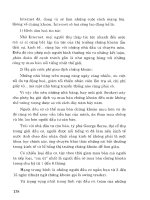
illustration). Note that it may be necessary to
TU engine in-car repair procedures 2A•3
3.4 Insert a 6 mm bolt (arrowed) through
hole in cylinder block flange and into
timing hole in the flywheel . . .
1.12 Engine code is stamped on a plate
(arrowed) attached to the front of the
cylinder block - viewed from above
2A
rotate the crankshaft slightly, to get the holes
to align.
5 With the flywheel correctly positioned,
insert a 10 mm diameter bolt or a drill through
the timing hole in the camshaft sprocket, and
locate it in the hole in the cylinder head (see
illustration).
6 The crankshaft and camshaft are now
locked in position, preventing unnecessary
rotation.
4 Cylinder head cover -
removal and refitting
2
Removal
1 Disconnect the battery negative lead.
2 Where necessary, undo the bolts securing
the HT lead retaining clips to the rear of the
cylinder head cover, and position the clips
clear of the cover.
3 Slacken the retaining clip, and disconnect
the breather hose from the left-hand end of
the cylinder head cover (see illustration).
Where the original crimped-type Peugeot
hose clip is still fitted, cut it off and discard it.
Use a standard worm-drive clip on refitting.
4 Undo the two retaining nuts, and remove
the washer from each of the cylinder head
cover studs (see illustration).
5 Lift off the cylinder head cover, and remove
it along with its rubber seal (see illustration).
Examine the seal for signs of damage and
deterioration, and if necessary, renew it.
6 Lift off the spacer from each stud, and
remove the oil baffle plate (see illustrations).
Refitting
7 Carefully clean the cylinder head and cover
mating surfaces, and remove all traces of oil.
8 Fit the rubber seal over the edge of the
cylinder head cover, ensuring that it is
correctly located along its entire length (see
illustration).
9 Refit the oil baffle plate to the engine, and
locate the spacers in their recesses in the
baffle plate.
10 Carefully refit the cylinder head cover to
the engine, taking great care not to displace
the rubber seal.
11 Check that the seal is correctly located,
then refit the washers and cover retaining
nuts, and tighten them to the specified torque.
12 Where necessary, refit the HT lead clips to
the rear of the head cover, and securely
tighten their retaining bolts.
13 Reconnect the breather hose to the
cylinder head cover, securely tightening its
retaining clip, and reconnect the battery
negative lead.
5 Timing belt covers - removal
and refitting
2
Removal
Upper cover
1 Slacken and remove the two retaining bolts
(one at the front and one at the rear), and
remove the upper timing cover from the
cylinder head (see illustrations).
Centre cover
2 Remove the upper cover as described in
paragraph 1, then free the wiring from its clips
on the centre cover (see illustration).
3 Slacken and remove the three retaining
bolts (one at the rear of the cover, beneath the
engine mounting plate, and two directly above
the crankshaft pulley), and manoeuvre the
centre cover out from the engine
compartment (see illustration).
Lower cover
4 Remove the auxiliary drivebelt as described
in Chapter 1.
5 Remove the upper and centre covers as
described in paragraphs 1 to 3.
4.8 On refitting, ensure the rubber seal is
located on the cylinder head cover
2A•4 TU engine in-car repair procedures
3.5 . . . then insert a 10 mm bolt through
the cam sprocket timing hole, and locate it
in the cylinder head
4.4 . . . then slacken and remove the cover
retaining nuts and washers (arrowed) . . .
4.6b . . . and remove the oil baffle plate4.6a Lift off the spacers
(second one arrowed) . . .
4.5 . . . and lift off the cylinder head cover4.3 Disconnect the breather hose from the
cylinder head cover . . .
6 Undo the three crankshaft pulley retaining
bolts and remove the pulley, noting which way
round it is fitted (see illustrations).
7 Slacken and remove the single retaining
bolt, and slide the lower cover off the end of
the crankshaft (see illustration).
Refitting
Upper cover
8 Refit the cover, ensuring it is correctly
located with the centre cover, and tighten its
retaining bolts.
Centre cover
9 Manoeuvre the centre cover back into
position, ensuring it is correctly located with
the lower cover, and tighten its retaining bolts.
10 Clip the wiring loom into its retaining clips
on the front of the centre cover, then refit the
upper cover as described in paragraph 8.
Lower cover
11 Locate the lower cover over the timing
belt sprocket, and tighten its retaining bolt.
12 Fit the pulley to the end of the crankshaft,
ensuring it is fitted the correct way round, and
tighten its retaining bolts to the specified
torque.
13 Refit the centre and upper covers as
described above, then refit and tension the
auxiliary drivebelt as described in Chapter 1.
6 Timing belt -
general information,
removal and refitting
4
Note: Peugeot specify the use of a special
electronic tool (SEEM C.TRONIC type 105 or
105.5 belt tensioning measuring tool) to
correctly set the timing belt tension. If access
to this equipment cannot be obtained, an
approximate setting can be achieved using
the method described below. If the method
described is used, the tension must be
checked using the special electronic tool at
the earliest possible opportunity. Do not drive
the vehicle over large distances, or use high
engine speeds, until the belt tension is known
to be correct. Refer to a Peugeot dealer for
advice.
General information
1 The timing belt drives the camshaft and
coolant pump from a toothed sprocket on the
front of the crankshaft. If the belt breaks or
slips in service, the pistons are likely to hit the
valve heads, resulting in extensive (and
expensive) damage.
2 The timing belt should be renewed at the
specified intervals (see Chapter 1), or earlier if
it is contaminated with oil, or if it is at all noisy
in operation (a “scraping” noise due to uneven
wear).
3 If the timing belt is being removed, it is a
wise precaution to check the condition of the
coolant pump at the same time (check for
signs of coolant leakage). This may avoid the
need to remove the timing belt again at a later
stage, should the coolant pump fail.
Removal
4 Disconnect the battery negative terminal.
5 Align the engine assembly/valve timing
holes as described in Section 3, and lock both
the camshaft sprocket and the flywheel in
position. Do not attempt to rotate the engine
whilst the locking tools are in position.
6 Remove the timing belt centre and lower
covers as described in Section 5.
7 Loosen the timing belt tensioner pulley
retaining nut. Pivot the pulley in a clockwise
direction, using a square-section key fitted to
the hole in the pulley hub, then retighten the
retaining nut.
8 If the timing belt is to be re-used, use white
paint or similar to mark the direction of
rotation on the belt (if markings do not already
exist) (see illustration). Slip the belt off the
sprockets.
9 Check the timing belt carefully for any signs
of uneven wear, splitting, or oil contamination.
Pay particular attention to the roots of the
teeth. Renew the belt if there is the slightest
TU engine in-car repair procedures 2A•5
5.2 Free the wiring loom from its
retaining clip . . .
5.6b . . . and remove the crankshaft pulley5.6a Undo the three retaining bolts
(arrowed) . . .
5.3 . . . then undo the three bolts (locations
arrowed) and remove the centre belt cover
5.1b . . . and remove the
upper timing belt cover
5.1a Undo the two retaining bolts
(arrowed) . . .
2A
5.7 Undo the retaining bolt and remove
the lower timing belt cover
doubt about its condition. If the engine is
undergoing an overhaul, and has covered
more than 36 000 miles (60 000 km) with the
existing belt fitted, renew the belt as a matter
of course, regardless of its apparent
condition. The cost of a new belt is nothing
when compared to the cost of repairs, should
the belt break in service. If signs of oil
contamination are found, trace the source of
the oil leak, and rectify it. Wash down the
engine timing belt area and all related
components, to remove all traces of oil.
Refitting
10 Prior to refitting, thoroughly clean the
timing belt sprockets. Check that the
tensioner pulley rotates freely, without any
sign of roughness. If necessary, renew the
tensioner pulley as described in Section 7.
Make sure that the locking tools are still in
place, as described in Section 3.
11 Manoeuvre the timing belt into position,
ensuring the arrows on the belt are pointing in
the direction of rotation (clockwise, when
viewed from the right-hand end of the engine).
12 Do not twist the timing belt sharply while
refitting it. Fit the belt over the crankshaft and
camshaft sprockets. Make sure that the “front
run” of the belt is taut - ie, ensure that any
slack is on the tensioner pulley side of the
belt. Fit the belt over the coolant pump
sprocket and tensioner pulley. Ensure that the
belt teeth are seated centrally in the
sprockets.
13 Loosen the tensioner pulley retaining nut.
Pivot the pulley anti-clockwise to remove all
free play from the timing belt, then retighten
the nut. Tension the timing belt as described
under the relevant sub-heading.
Tensioning without the special
electronic measuring tool
Note: If this method is used, ensure that the
belt tension is checked by a Peugeot dealer at
the earliest possible opportunity.
14 Peugeot dealers use a special tool to
tension the timing belt. A similar tool may be
fabricated using a suitable square-section bar
attached to an arm made from a metal strip; a
hole should be drilled in the strip at a distance
of 80 mm from the centre of the square-
section bar. Fit the tool to the hole in the
tensioner pulley, keeping the tool arm as close
to the horizontal as possible, and hang a 1.5
kg (3.3 lb) weight (aluminium block engine) or
2.0 kg (4.4 lb) weight (cast-iron block engine)
from the hole in the tool (see illustration). In
the absence of an object of the specified
weight, a spring balance can be used to exert
the required force, ensuring that the spring
balance is held at 90° to the tool arm. Slacken
the pulley retaining nut, allowing the weight or
force exerted (as applicable) to push the
tensioner pulley against the belt, then
retighten the pulley nut.
15 If this special tool is not available, an
approximate setting may be achieved by
pivoting the tensioner pulley anti-clockwise
until it is just possible to twist the timing belt
through 90° by finger and thumb, midway
between the crankshaft and camshaft
sprockets. The deflection of the belt at the
mid-point between the sprockets should be
approximately 6.0 mm.
16 Remove the locking tools from the
camshaft sprocket and flywheel.
17 Using a suitable socket and extension bar
on the crankshaft sprocket bolt, rotate the
crankshaft through four complete rotations in
a clockwise direction (viewed from the right-
hand end of the engine). Do not at any time
rotate the crankshaft anti-clockwise.
18 Slacken the tensioner pulley nut, re-
tension the belt as described in paragraph 14
or 15, then tighten the tensioner pulley nut to
the specified torque.
19 Rotate the crankshaft through a further
two turns clockwise, and check that both the
camshaft sprocket and flywheel timing holes
are still correctly aligned.
20 If all is well, refit the timing belt covers as
described in Section 5, and reconnect the
battery negative terminal.
Tensioning using the special
electronic measuring tool
21 Fit the special belt tensioning measuring
equipment to the “front run” of the timing belt,
approximately midway between the camshaft
and crankshaft sprockets. Position the
tensioner pulley so that the belt is tensioned
to a setting of 45 units, then retighten its
retaining nut.
22 Remove the locking tools from the
camshaft sprocket and flywheel, and remove
the measuring tool from the belt.
23 Using a suitable socket and extension bar
on the crankshaft sprocket bolt, rotate the
crankshaft through four complete rotations in
a clockwise direction (viewed from the right-
hand end of the engine). Do not at any time
rotate the crankshaft anti-clockwise.
24 Slacken the tensioner pulley retaining nut,
and refit the measuring tool to the belt. If a
“new” belt is being fitted, tension it to a
setting of 40 units. If an “old” belt is being re-
used, tighten it to a setting of 36 units. Note:
Peugeot state that a belt becomes “old” after
1 hour’s use. With the belt correctly
tensioned, tighten the pulley retaining nut to
the specified torque.
25 Remove the measuring tool from the belt,
then rotate the crankshaft through another
two complete rotations in a clockwise
direction, so that both the camshaft sprocket
and flywheel timing holes are realigned. Do
not at any time rotate the crankshaft anti-
clockwise. Fit the measuring tool to the belt,
and check the belt tension. A “new” belt
should give a reading of 51 ± 3 units; an “old”
belt should be 45 ± 3 units.
26 If the belt tension is incorrect, repeat the
procedures in paragraphs 24 and 25.
27 With the belt tension correctly set, refit the
timing belt covers as described in Section 5,
and reconnect the battery negative terminal.
7 Timing belt tensioner and
sprockets - removal,
inspection and refitting
4
Note: This Section describes the removal and
refitting of the components concerned as
individual operations. If more than one of them
is to be removed at the same time, start by
removing the timing belt as described in
Section 6; remove the actual component as
described below, ignoring the preliminary
dismantling steps.
Removal
1 Disconnect the battery negative terminal.
2 Position the engine assembly/valve timing
holes as described in Section 3, and lock both
the camshaft sprocket and flywheel in
position. Do not attempt to rotate the engine
whilst the pins are in position.
Camshaft sprocket
3 Remove the centre timing belt cover as
described in Section 5.
2A•6 TU engine in-car repair procedures
6.8 Mark the direction of rotation on the
belt, if it is to be re-used
6.14 Using the Peugeot special tool to
tension the timing belt
4 Loosen the timing belt tensioner pulley
retaining nut. Rotate the pulley in a clockwise
direction, using a suitable square-section key
fitted to the hole in the pulley hub, then
retighten the retaining nut.
5 Disengage the timing belt from the
sprocket, and move the belt clear, taking care
not to bend or twist it sharply. Remove the
locking pin from the camshaft sprocket.
6 Slacken the camshaft sprocket retaining
bolt and remove it, along with its washer. To
prevent the camshaft rotating as the bolt is
slackened, a sprocket-holding tool will be
required. In the absence of the special
Peugeot tool, an acceptable substitute can be
fabricated as follows. Use two lengths of steel
strip (one long, the other short), and three nuts
and bolts; one nut and bolt forms the pivot of
a forked tool, with the remaining two nuts and
bolts at the tips of the “forks” to engage with
the sprocket spokes as shown in the
accompanying “Tool Tip”. Do not attempt to
use the sprocket locking pin to prevent the
sprocket from rotating whilst the bolt is
slackened.
7 With the retaining bolt removed, slide the
sprocket off the end of the camshaft. If the
locating peg is a loose fit in the rear of the
sprocket, remove it for safe-keeping. Examine
the camshaft oil seal for signs of oil leakage
and, if necessary, renew it as described in
Section 8.
Crankshaft sprocket
8 Remove the centre and lower timing belt
covers as described in Section 5.
9 Remove the timing belt from the sprockets
as described in Section 6.
10 To prevent crankshaft rotation whilst the
sprocket retaining bolt is slackened, select
4th gear, and have an assistant apply the
brakes firmly. If the engine has been removed
from the vehicle, lock the flywheel ring gear,
using an arrangement similar to that shown
(see illustration). Do not be tempted to use
the flywheel locking pin to prevent the
crankshaft from rotating; temporarily remove
the locking pin from the rear of the flywheel
prior to slackening the pulley bolt, then refit it
once the bolt has been slackened. Do not
allow the crankshaft to turn more than a few
degrees while loosening the bolt otherwise
the pistons may touch the valves.
11 Unscrew the retaining bolt and washer,
then slide the sprocket off the end of the
crankshaft (see illustrations). Refit the
locating pin to the rear of the timing hole in the
rear of the flywheel.
12 If the Woodruff key is a loose fit in the
crankshaft, remove it and store it with the
sprocket for safe-keeping. If necessary, also
slide the flanged spacer off the end of the
crankshaft (see illustration). Examine the
crankshaft oil seal for signs of oil leakage and,
if necessary, renew it (refer to Section 14).
Tensioner pulley
13 Remove the centre timing belt cover as
described in Section 5.
14 Slacken and remove the timing belt
tensioner pulley retaining nut, and slide the
pulley off its mounting stud. Examine the
mounting stud for signs of damage and, if
necessary, renew it.
Inspection
15 Clean the sprockets thoroughly, and
renew any that show signs of wear, damage
or cracks.
16 Clean the tensioner assembly, but do not
use any strong solvent which may enter the
pulley bearing. Check that the pulley rotates
freely about its hub, with no sign of stiffness
or free play. Renew the tensioner pulley if
there is any doubt about its condition, or if
there are any obvious signs of wear or
damage.
Refitting
Camshaft sprocket
17 Refit the locating peg (where removed) to
the rear of the sprocket, then locate the
sprocket on the end of the camshaft. Ensure
that the locating peg is correctly engaged with
the cutout in the camshaft end.
18 Refit the sprocket retaining bolt and
washer. Tighten the bolt to the specified
torque, whilst retaining the sprocket with the
tool used on removal (see Tool Tip).
19 Realign the timing hole in the camshaft
sprocket (see Section 3) with the
corresponding hole in the cylinder head, and
refit the locking pin.
20 Refit the timing belt to the camshaft
sprocket. Ensure that the “front run” of the
belt is taut - ie, ensure that any slack is on the
tensioner pulley side of the belt. Do not twist
the belt sharply while refitting it, and ensure
that the belt teeth are seated centrally in the
sprockets.
21 Loosen the tensioner pulley retaining nut.
Rotate the pulley anti-clockwise to remove all
free play from the timing belt, then retighten
the nut.
22 Tension the belt as described in
paragraphs 14 to 19 of Section 6.
23 Refit the timing belt covers as described
in Section 5.
Crankshaft sprocket
24 Where removed, locate the Woodruff key
in the crankshaft end, then slide on the
TU engine in-car repair procedures 2A•7
7.11b . . . then slide off the sprocket 7.12 Remove the flanged spacer if
necessary
7.11a Remove the crankshaft sprocket
retaining bolt . . .
7.10 Use the fabricated tool shown to lock
flywheel ring gear and prevent the
crankshaft rotating
2A
Using a home-made tool to hold the
camshaft sprocket stationary whilst the
retaining bolt is tightened (shown with
cylinder head removed)
flanged spacer, aligning its slot with the
Woodruff key.
25 Align the crankshaft sprocket slot with the
Woodruff key, and slide it onto the end of the
crankshaft.
26 Temporarily remove the locking pin from
the rear of the flywheel, then refit the
crankshaft sprocket retaining bolt and
washer. Tighten the bolt to the specified
torque, whilst preventing crankshaft rotation
using the method employed on removal. Refit
the locking pin to the rear of the flywheel.
27 Relocate the timing belt on the sprockets.
Ensure that the “front run” of the belt is taut -
ie, ensure that any slack is on the tensioner
pulley side of the belt. Do not twist the belt
sharply while refitting it, and ensure that the
belt teeth are seated centrally in the
sprockets.
28 Loosen the tensioner pulley retaining nut.
Rotate the pulley anti-clockwise to remove all
free play from the timing belt, then retighten
the nut.
29 Tension the belt as described in
paragraphs 14 to 19 of Section 6.
30 Refit the timing belt covers as described
in Section 5.
Tensioner pulley
31 Refit the tensioner pulley to its mounting
stud, and fit the retaining nut.
32 Ensure that the “front run” of the belt is
taut - ie, ensure that any slack is on the pulley
side of the belt. Check that the belt is centrally
located on all its sprockets. Rotate the pulley
anti-clockwise to remove all free play from the
timing belt, then tighten the pulley retaining
nut securely.
33 Tension the belt as described in
paragraphs 14 to 19 of Section 6.
34 Refit the timing belt covers as described
in Section 5.
8 Camshaft oil seal - renewal
4
Note: If the camshaft oil seal is to be renewed
with the timing belt still in place, check first
that the belt is free from oil contamination.
(Renew the belt as a matter of course if signs
of oil contamination are found; see Section 6.)
Cover the belt to protect it from oil
contamination while work is in progress.
Ensure that all traces of oil are removed from
the area before the belt is refitted.
1 Remove the camshaft sprocket as
described in Section 7.
2 Punch or drill two small holes opposite
each other in the oil seal. Screw a self-tapping
screw into each, and pull on the screws with
pliers to extract the seal.
3 Clean the seal housing, and polish off any
burrs or raised edges, which may have
caused the seal to fail in the first place.
4 Lubricate the lips of the new seal with clean
engine oil, and drive it into position until it
seats on its locating shoulder. Use a suitable
tubular drift, such as a socket, which bears
only on the hard outer edge of the seal. Take
care not to damage the seal lips during fitting.
Note that the seal lips should face inwards.
5 Refit the camshaft sprocket as described in
Section 7.
9 Valve clearances - checking
and adjustment
3
Note: The valve clearances must be checked
and adjusted only when the engine is cold.
1 The importance of having the valve
clearances correctly adjusted cannot be
overstressed, as they vitally affect the
performance of the engine. If the clearances
are too big, the engine will be noisy (charac-
teristic rattling or tapping noises) and engine
efficiency will be reduced, as the valves open
too late and close too early. A more serious
problem arises if the clearances are too small,
however. If this is the case, the valves may not
close fully when the engine is hot, resulting in
serious damage to the engine (eg. burnt valve
seats and/or cylinder head warping/cracking).
The clearances are checked and adjusted as
follows.
2 Remove the cylinder head cover and oil
baffle plate as described in Section 4.
3 The engine can now be turned using a
suitable socket and extension bar fitted to the
crankshaft sprocket/pulley bolt.
4 It is important that the clearance of each
valve is checked and adjusted only when the
valve is fully closed, with the rocker arm
resting on the heel of the cam (directly
opposite the peak). This can be ensured by
carrying out the adjustments in the following
sequence, noting that No 1 cylinder is at the
transmission end of the engine. The correct
valve clearances are given in the Specifica-
tions at the start of this Chapter. The valve
locations can be determined from the position
of the manifolds.
Valve fully Adjust valves
open
No 1 exhaust No 3 inlet and No 4 exhaust
No 3 exhaust No 4 inlet and No 2 exhaust
No 4 exhaust No 2 inlet and No 1 exhaust
No 2 exhaust No 1 inlet and No 3 exhaust
5 With the relevant valve fully open, check the
clearances of the two valves specified.
Clearances are checked by inserting a feeler
blade of the correct thickness between the
valve stem and the rocker arm adjusting
screw. The feeler blade should be a light,
sliding fit. If adjustment is necessary, slacken
the adjusting screw locknut, and turn the
screw as necessary. Once the correct
clearance is obtained, hold the adjusting
screw and securely tighten the locknut.
Recheck the valve clearance, and adjust
again if necessary.
6 Rotate the crankshaft until the next valve in
the sequence is fully open, and check the
clearances of the next two specified valves.
7 Repeat the procedure until all eight valve
clearances have been checked (and if
necessary, adjusted), then refit the oil baffle
plate and cylinder head cover as described in
Section 4.
10 Camshaft and rocker arms -
removal, inspection and
refitting
4
General information
1 The rocker arm assembly is secured to the
top of the cylinder head by the cylinder head
bolts. Although in theory, it is possible to undo
the head bolts and remove the rocker arm
assembly without removing the head, in
practice, this is not recommended. Once the
bolts have been removed, the head gasket will
be disturbed, and the gasket will almost
certainly leak or blow after refitting. For this
reason, removal of the rocker arm assembly
cannot be done without removing the cylinder
head and renewing the head gasket.
2 The camshaft is slid out of the right-hand
end of the cylinder head, and it therefore
cannot be removed without first removing the
cylinder head, due to a lack of clearance.
Removal
Rocker arm assembly
3 Remove the cylinder head as described in
Section 11.
4 To dismantle the rocker arm assembly,
carefully prise off the circlip from the right-
hand end of the rocker shaft; retain the rocker
pedestal, to prevent it being sprung off the
end of the shaft. Slide the various
components off the end of the shaft, keeping
all components in their correct fitted order
(see illustration). Make a note of each
component’s correct fitted position and
orientation as it is removed, to ensure it is
fitted correctly on reassembly.
2A•8 TU engine in-car repair procedures
10.4 Remove the circlip, and slide the
components off the end of the rocker arm
Turning the engine will be
easier if the spark plugs are
removed first - see Chapter 1
5 To separate the left-hand pedestal and
shaft, first unscrew the cylinder head cover
retaining stud from the top of the pedestal;
this can be achieved using a stud extractor, or
alternatively, by using two nuts locked
together. With the stud removed, unscrew the
grub screw from the top of the pedestal, and
carefully withdraw the rocker shaft (see
illustrations).
Camshaft
6 Remove the cylinder head as described in
Section 11.
7 With the head on a bench, remove the
locking pin, then remove the camshaft
sprocket as described in paragraphs 6 and 7
of Section 7.
8 Unbolt the housing from the left-hand end
of the cylinder head, then undo the retaining
bolt, and remove the camshaft thrust fork
from the cylinder head (see illustration).
9 Using a large flat-bladed screwdriver,
carefully prise the oil seal out of the right-
hand end of the cylinder head, then carefully
slide out the camshaft (see illustrations).
Discard the seal - a new one must be used on
refitting.
Inspection
Rocker arm assembly
10 Examine the rocker arm bearing surfaces
which contact the camshaft lobes for wear
ridges and scoring. Renew any rocker arms
on which these conditions are apparent. If a
rocker arm bearing surface is badly scored,
also examine the corresponding lobe on the
camshaft for wear, as it is likely that both will
be worn. Renew worn components as
necessary. The rocker arm assembly can be
dismantled as described in paragraphs 4
and 5.
11 Inspect the ends of the (valve clearance)
adjusting screws for signs of wear or damage,
and renew as required.
12 If the rocker arm assembly has been
dismantled, examine the rocker arm and shaft
bearing surfaces for wear ridges and scoring.
If there are obvious signs of wear, the relevant
rocker arm(s) and/or the shaft must be
renewed.
Camshaft
13 Examine the camshaft bearing surfaces
and cam lobes for signs of wear ridges and
scoring. Renew the camshaft if any of these
conditions are apparent. Examine the condition
of the bearing surfaces, both on the camshaft
journals and in the cylinder head. If the head
bearing surfaces are worn excessively, the
cylinder head will need to be renewed. If the
necessary measuring equipment is available,
camshaft bearing journal wear can be checked
by direct measurement, noting that No 1
journal is at the transmission end of the head.
14 Examine the thrust fork for signs of wear
or scoring, and renew as necessary.
Refitting
Rocker arm assembly
15 If the rocker arm assembly was
dismantled, refit the rocker shaft to the left-
hand pedestal, aligning its locating hole with
the pedestal threaded hole. Refit the grub
screw, and tighten it securely. With the grub
screw in position, refit the cylinder head cover
mounting stud to the pedestal, and tighten it
securely. Apply a smear of clean engine oil to
the shaft, then slide on all removed
components, ensuring each is correctly fitted
in its original position. Once all components
are in position on the shaft, compress the
right-hand pedestal and refit the circlip.
Ensure that the circlip is correctly located in
its groove on the shaft.
16 Refit the cylinder head and rocker arm
assembly as described in Section 11.
Camshaft
17 Ensure that the cylinder head and
camshaft bearing surfaces are clean, then
liberally oil the camshaft bearings and lobes.
Slide the camshaft back into position in the
cylinder head. On carburettor engines, take
care that the fuel pump operating lever is not
trapped by the camshaft as it is slid into
position. To prevent this, remove the fuel
pump before refitting the camshaft, then refit
it afterwards.
18 Locate the thrust fork with the left-hand
end of the camshaft. Refit the fork retaining
bolt, tightening it to the specified torque
setting.
19 Ensure that the housing and cylinder head
mating surfaces are clean and dry, then apply
a smear of sealant to the housing mating
surface. Refit the housing to the left-hand end
of the head, and securely tighten its retaining
bolts.
20 Lubricate the lips of the new seal with
clean engine oil, then drive it into position until
it seats on its locating shoulder. Use a
suitable tubular drift, such as a socket, which
bears only on the hard outer edge of the seal.
Take care not to damage the seal lips during
fitting. Note that the seal lips should face
inwards.
21 Refit the camshaft sprocket as described
in paragraphs 17 to 19 of Section 7.
22 Refit the cylinder head as described in
Section 11.
TU engine in-car repair procedures 2A•9
10.8 Undo the retaining bolt, and remove
the camshaft thrust fork (arrowed) . . .
10.9b . . . and slide out the camshaft10.9a . . . prise out the oil seal . . .
10.5b . . . then remove the grub screw10.5a To remove the left-hand pedestal,
lock two nuts together
and unscrew the stud . . .
2A
11 Cylinder head -
removal and refitting
4
Removal
1 Disconnect the battery negative lead.
2 Drain the cooling system (see Chapter 1).
3 Remove the cylinder head cover and oil
baffle plate as described in Section 4.
4 Align the engine assembly/valve timing
holes as described in Section 3, and lock both
the camshaft sprocket and flywheel in
position. Do not attempt to rotate the engine
whilst the tools are in position.
5 Note that the following text assumes that
the cylinder head will be removed with both
inlet and exhaust manifolds attached; this is
easier, but makes it a bulky and heavy
assembly to handle. If it is wished to remove
the manifolds first, proceed as described in
the relevant Part of Chapter 4.
6 Working as described in the relevant Part of
Chapter 4, disconnect the exhaust system
front pipe from the manifold. Where fitted,
disconnect or release the lambda sensor
wiring, so that it is not strained by the weight
of the exhaust.
7 Remove the air cleaner housing and inlet
duct assembly as described in Chapter 4.
8 On carburettor engines, disconnect the
following from the carburettor and inlet
manifold as described in Chapter 4A:
a) Fuel feed hose from the pump and the
return hose from the anti-percolation
chamber (plug all openings, to prevent
loss of fuel and the entry of dirt into the
system).
b) Accelerator cable.
c) Choke cable.
d) Carburettor heating element and idle cut-
off solenoid wiring connector(s).
e) Vacuum servo unit vacuum hose, coolant
hose and all other relevant
breather/vacuum hoses from the
manifold.
9 On fuel injection engines, carry out the
following operations as described in the
relevant Part of Chapter 4:
a) Depressurise the fuel system, and
disconnect the fuel feed and return hoses
from the throttle body/fuel rail (plug all
openings, to prevent loss of fuel and entry
of dirt into the fuel system).
b) Disconnect the accelerator cable.
c) On single-point injection models,
disconnect the relevant electrical
connectors from the throttle body.
d) On multi-point injection models,
disconnect the relevant electrical
connectors from the throttle housing, fuel
injectors and (where necessary) the idle
speed auxiliary air valve.
e) Disconnect the vacuum servo unit hose,
coolant hose(s) and all the other
relevant/breather hoses from the
manifold.
10 Remove the centre timing belt cover as
described in Section 5.
11 Loosen the timing belt tensioner pulley
retaining nut. Pivot the pulley in a clockwise
direction, using a suitable square-section key
fitted to the hole in the pulley hub, then
retighten the retaining nut.
12 Disengage the timing belt from the
camshaft sprocket, and position the belt clear
of the sprocket. Ensure that the belt is not
bent or twisted sharply.
13 Slacken the retaining clips, and
disconnect the coolant hoses from the
thermostat housing (on the left-hand end of
the cylinder head).
14 Depress the retaining clip(s), and
disconnect the wiring connector(s) from the
electrical switch and/or sensor(s) which are
screwed into the thermostat housing/cylinder
head (as appropriate). Also where necessary,
release the TDC connector from its support
on the distributor bracket on the left-hand end
of the cylinder head.
Carburettor models
15 Disconnect the LT wiring connectors from
the distributor and HT coil. Release the TDC
sensor wiring connector from the side of the
coil mounting bracket, and disconnect the
vacuum pipe from the distributor vacuum
diaphragm unit. If the cylinder head is to be
dismantled for overhaul, remove the
distributor and ignition HT coil as described in
Chapter 5. If the cylinder numbers are not
already marked on the HT leads, number each
lead, to avoid the possibility of the leads being
incorrectly connected on refitting. Disconnect
the HT leads from the spark plugs, and
remove the distributor cap and lead
assembly.
Fuel-injected models
16 Disconnect the wiring connector from the
ignition HT coil. If the cylinder head is to be
dismantled for overhaul, remove the ignition
HT coil as described in Chapter 5. If the
cylinder numbers are not already marked on
the HT leads, number each lead, to avoid the
possibility of the leads being incorrectly
connected on refitting. Note that the HT leads
should be disconnected from the spark plugs
instead of the coil, and the coil and leads
removed as an assembly.
All models
17 Slacken and remove the bolt securing the
engine oil dipstick tube to the cylinder head.
18 Working in the reverse of the sequence
shown in illustration 11.38a, progressively
slacken the ten cylinder head bolts by half a
turn at a time, until all bolts can be unscrewed
by hand.
19 With all the cylinder head bolts removed,
lift the rocker arm assembly off the cylinder
head. Note the locating pins which are fitted
to the base of each rocker arm pedestal. If
any pin is a loose fit in the head or pedestal,
remove it for safe-keeping.
20 On engines with a cast-iron cylinder
block, lift the cylinder head away; seek
assistance if possible, as it is a heavy
assembly, especially if it is being removed
complete with the manifolds.
21 On engines with an aluminium cylinder
block, the joint between the cylinder head and
gasket and the cylinder block/crankcase must
now be broken without disturbing the wet
liners. To break the joint, obtain two L-shaped
metal bars which fit into the cylinder head bolt
holes. Gently “rock” the cylinder head free
towards the front of the car (see illustration).
Do not try to swivel the head on the cylinder
block/crankcase; it is located by dowels, as
well as by the tops of the liners. Note: If care
is not taken and the liners are moved, there is
also a possibility of the bottom seals being
disturbed, causing leakage after refitting the
head. When the joint is broken, lift the cylinder
head away; seek assistance if possible, as it is
a heavy assembly, especially if it is being
removed complete with the manifolds.
22 On all models, remove the gasket from
the top of the block, noting the two locating
dowels. If the locating dowels are a loose fit,
remove them and store them with the head for
safe-keeping. Do not discard the gasket - on
some models it will be needed for identifi-
cation purposes (see paragraphs 28 and 29).
Caution: On aluminium block engines, do
not attempt to rotate the crankshaft with
the cylinder head removed, otherwise the
wet liners may be displaced. Operations
that require the rotation of the crankshaft
(eg cleaning the piston crowns), should
only be carried out once the cylinder liners
are firmly clamped in position. In the
absence of the special Peugeot liner
clamps, the liners can be clamped in
position using large flat washers
positioned underneath suitable-length
bolts. Alternatively, the original head bolts
could be temporarily refitted, with suitable
spacers fitted to their shanks.
23 If the cylinder head is to be dismantled for
overhaul, remove the camshaft as described
in Section 10, then refer to Part C of this
Chapter.
Preparation for refitting
24 The mating faces of the cylinder head and
cylinder block/crankcase must be perfectly
clean before refitting the head. Use a hard
2A•10 TU engine in-car repair procedures
11.21 Using two angled metal rods to free
the cylinder head from the block
plastic or wood scraper to remove all traces of
gasket and carbon; also clean the piston
crowns. Refer to paragraph 23 before turning
the crankshaft on aluminium block engines.
Take particular care during the cleaning
operations, as aluminium alloy is easily
damaged. Also, make sure that the carbon is
not allowed to enter the oil and water
passages - this is particularly important for the
lubrication system, as carbon could block the
oil supply to the engine’s components. Using
adhesive tape and paper, seal the water, oil
and bolt holes in the cylinder
block/crankcase. To prevent carbon entering
the gap between the pistons and bores,
smear a little grease in the gap. After cleaning
each piston, use a small brush to remove all
traces of grease and carbon from the gap,
then wipe away the remainder with a clean
rag. Clean all the pistons in the same way.
25 Check the mating surfaces of the cylinder
block/crankcase and the cylinder head for
nicks, deep scratches and other damage. If
slight, they may be removed carefully with a
file, but if excessive, machining may be the
only alternative to renewal.
26 If warpage of the cylinder head gasket
surface is suspected, use a straight-edge to
check it for distortion. Refer to Part C of this
Chapter if necessary.
27 When purchasing a new cylinder head
gasket, it is essential that a gasket of the
correct thickness is obtained. On some
models only one thickness of gasket is
available, so this is not a problem. However,
on all other models, there are two different
thicknesses available - the standard gasket
which is fitted at the factory, and a slightly
thicker “repair” gasket (+ 0.2 mm), for use
once the head gasket face has been
machined. If the cylinder head has been
machined, it should have the letter “R”
stamped adjacent to the No 3 exhaust port,
and the gasket should also have the letter “R”
stamped adjacent to No 3 cylinder on its front
upper face. The gaskets can also be identified
as described in the following paragraph, using
the cut-outs on the left-hand end of the
gasket.
28 With the gasket fitted the correct way up
on the cylinder block, there will be a single
cut-out, or no cut-out at all, at the rear of the
left-hand side of the gasket identifying the
engine type (ie. TU engine). In the centre of
the gasket there may be another series of
between 0 and 4 cut-outs, identifying the
manufacturer of the gasket and whether or
not it contains asbestos (these cut-outs are of
little importance). The important cut-out
location is at the front of the gasket; on the
standard gasket there will be no cut-out in this
position, whereas on the thicker “repair”
gasket there will be a single cut-out (see
illustration). Identify the gasket type, and
ensure that the new gasket obtained is of the
correct thickness. If there is any doubt as to
which gasket is fitted, take the old gasket
along to your Peugeot dealer, and have him
confirm the gasket type.
29 Check the condition of the cylinder head
bolts, and particularly their threads, whenever
they are removed. Wash the bolts in suitable
solvent, and wipe them dry. Check each for
any sign of visible wear or damage, renewing
any bolt if necessary. Measure the length of
each bolt, to check for stretching (although
this is not a conclusive test, in the event that
all ten bolts have stretched by the same
amount). Although Peugeot do not actually
specify that the bolts must be renewed, it is
strongly recommended that the bolts should
be renewed as a complete set whenever they
are disturbed.
30 On aluminium block engines, prior to
refitting the cylinder head, check the cylinder
liner protrusion as described in Part C of this
Chapter.
Refitting
31 Wipe clean the mating surfaces of the
cylinder head and cylinder block/crankcase.
Check that the two locating dowels are in
position at each end of the cylinder
block/crankcase surface and, if necessary,
remove the cylinder liner clamps.
32 Position a new gasket on the cylinder
block/crankcase surface, ensuring that its
identification cut-outs are at the left-hand end
of the gasket (see illustration) and the
manufacturer’s name is uppermost.
33 Check that the flywheel and camshaft
sprocket are still correctly locked in position
with their respective tools then, with the aid of
an assistant, carefully refit the cylinder head
assembly to the block, aligning it with the
locating dowels (see illustration).
34 Ensure that the locating pins are in
position in the base of each rocker pedestal,
then refit the rocker arm assembly to the
cylinder head (see illustration).
35 Apply a smear of grease to the threads,
and to the underside of the heads, of the
cylinder head bolts. Peugeot recommend the
use of Molykote G Rapid Plus grease
(available from your Peugeot dealer - a sachet
is supplied with the top-end gasket set); in the
absence of the specified grease, a good-
quality high-melting-point grease may be
used.
36 Carefully enter each bolt into its relevant
hole (do not drop them in) and screw in, by
hand only, until finger-tight.
37 Working progressively and in the
sequence shown, tighten the cylinder head
bolts to their Stage 1 torque setting, using a
torque wrench and suitable socket (see
illustrations).
38 Once all the bolts have been tightened to
their Stage 1 setting, working again in the
given sequence, angle-tighten the bolts
through the specified Stage 2 angle, using a
socket and extension bar. It is recommended
TU engine in-car repair procedures 2A•11
11.33 . . . then lower the cylinder head
into position . . .
11.34 . . . and refit the
rocker arm assembly
A Engine type identification cut-outs
B Gasket manufacturer identification cut-outs
C Gasket thickness identification cut-out
11.32 Locate the cylinder head gasket
on the block . . .
11.28 TU engine series gasket markings
2A
that an angle-measuring gauge is used during
this stage of the tightening, to ensure
accuracy (see illustration). If a gauge is not
available, use white paint to make alignment
marks between the bolt head and cylinder
head prior to tightening; the marks can then
be used to check that the bolt has been
rotated through the correct angle during
tightening.
39 On cast-iron block engines, it will then be
necessary to tighten the bolts through the
specified Stage 3 angle setting.
40 With the cylinder head bolts correctly
tightened, refit the dipstick tube retaining bolt
and tighten it securely.
41 Refit the timing belt to the camshaft
sprocket. Ensure that the “front run” of the
belt is taut - ie, ensure that any slack is on the
tensioner pulley side of the belt. Do not twist
the belt sharply while refitting it, and ensure
that the belt teeth are seated centrally in the
sprockets.
42 Loosen the tensioner pulley retaining nut.
Pivot the pulley anti-clockwise to remove all
free play from the timing belt, then retighten
the nut.
43 Tension the belt as described under the
relevant sub-heading in Section 6, then refit
the centre and upper timing belt covers as
described in Section 5.
Carburettor models
44 If the head was stripped for overhaul, refit
the distributor and HT coil as described in
Chapter 5, ensuring that the HT leads are
correctly reconnected. If the head was not
stripped, reconnect the wiring connector and
vacuum pipe to the distributor, and the HT
lead to the coil; clip the TDC sensor wiring
connector onto the coil bracket.
Fuel-injected models
45 If the head was stripped for overhaul, refit
the ignition HT coil and leads as described in
Chapter 5, ensuring that the leads are
correctly reconnected. If the head was not
stripped, simply reconnect the wiring
connector to the HT coil.
All models
46 Reconnect the wiring connector(s) to the
coolant switch/sensor(s) on the left-hand end
of the head.
47 Reconnect the coolant hoses to the
thermostat housing, securely tightening their
retaining clips.
48 Working as described in the relevant Part
of Chapter 4, carry out the following tasks:
a) Refit all disturbed wiring, hoses and
control cable(s) to the inlet manifold and
fuel system components.
b) On carburettor models, reconnect and
adjust the choke and accelerator cables.
c) On fuel injection models, reconnect and
adjust the accelerator cable.
d) Reconnect the exhaust system front pipe
to the manifold. Where applicable,
reconnect the lambda sensor wiring
connector.
e) Refit the air cleaner housing and inlet
duct.
49 Check and, if necessary, adjust the valve
clearances as described in Section 9.
50 On completion, reconnect the battery,
and refill the cooling system as described in
Chapter 1.
12 Sump - removal and refitting
2
Removal
1 Firmly apply the handbrake, then jack up
the front of the vehicle and support it on axle
stands (see “Jacking and Vehicle Support”).
Disconnect the battery negative lead.
2 Drain the engine oil, then clean and refit the
engine oil drain plug, tightening it to the
specified torque. If the engine is nearing its
service interval when the oil and filter are due
for renewal, it is recommended that the filter is
also removed, and a new one fitted. After
reassembly, the engine can then be refilled
with fresh oil. Refer to Chapter 1 for further
information.
3 Remove the exhaust system front pipe as
described in the relevant Part of Chapter 4.
4 Progressively slacken and remove all the
sump retaining nuts and bolts. On cast-iron
block engines, it may be necessary to unbolt
the flywheel cover plate from the transmission
to gain access to the left-hand sump bolts.
5 Break the joint by striking the sump with the
palm of your hand, then lower the sump and
withdraw it from underneath the vehicle (see
illustration).
6 While the sump is removed, take the
opportunity to check the oil pump pick-
up/strainer for signs of clogging or splitting. If
necessary, remove the pump as described in
Section 13, and clean or renew the strainer.
Refitting
7 Clean all traces of sealant from the mating
surfaces of the cylinder block/crankcase and
sump, then use a clean rag to wipe out the
sump and the engine’s interior.
8 Ensure that the sump and cylinder
block/crankcase mating surfaces are clean
and dry, then apply a coating of suitable
sealant to the sump mating surface.
9 Offer up the sump, locating it on its
retaining studs, and refit its retaining nuts and
bolts. Tighten the nuts and bolts evenly and
progressively to the specified torque.
10 Refit the exhaust front pipe as described
in the relevant Part of Chapter 4.
11 Replenish the engine oil (see Chapter 1).
13 Oil pump - removal,
inspection and refitting
3
Removal
1 Remove the sump (refer to Section 12).
2 Slacken and remove the three bolts
2A•12 TU engine in-car repair procedures
11.37a Cylinder head bolt tightening
sequence
11.38 . . . then through the angle
specified for stage 2
12.5 Slacken and remove the sump
retaining nuts and bolts, then remove
the sump from the engine
11.37b Working in the sequence shown,
tighten the head bolts first to the
stage 1 torque setting . . .
securing the oil pump in position (see
illustration). Disengage the pump sprocket
from the chain, and remove the oil pump. If
the pump locating dowel is a loose fit, remove
and store it with the retaining bolts for safe-
keeping.
Inspection
3 Examine the oil pump sprocket for signs of
damage and wear such as chipped or missing
teeth. If the sprocket is worn, the pump
assembly must be renewed, as the sprocket is
not available separately. It is also
recommended that the chain and drive
sprocket, fitted to the crankshaft, is renewed at
the same time. On aluminium block engines,
renewal of the chain and drive sprocket is an
involved operation requiring the removal of the
main bearing ladder, and therefore cannot be
carried out with the engine still fitted to the
vehicle. On cast-iron block engines, the oil
pump drive sprocket and chain can be
removed with the engine in situ, once the
crankshaft sprocket has been removed and the
crankshaft oil seal housing has been unbolted.
Refer to Part D for further information.
4 Slacken and remove the bolts securing the
strainer cover to the pump body, then lift off
the strainer cover. Remove the relief valve
piston and spring (and guide pin - cast-iron
block engines only), noting which way round
they are fitted.
5 Examine the pump rotors and body for
signs of wear ridges and scoring. If worn, the
complete pump assembly must be renewed.
6 Examine the relief valve piston for signs of
wear or damage, and renew if necessary. The
condition of the relief valve spring can only be
measured by comparing it with a new one; if
there is any doubt about its condition, it
should also be renewed. Both the piston and
spring are available individually.
7 Thoroughly clean the oil pump strainer with
a suitable solvent, and check it for signs of
clogging or splitting. If the strainer is
damaged, the strainer and cover assembly
must be renewed.
8 Locate the relief valve spring, piston and
(where fitted) the guide pin in the strainer
cover, then refit the cover to the pump body.
Align the relief valve piston with its bore in the
pump. Refit the cover retaining bolts,
tightening them securely.
Refitting
9 Ensure that the locating dowel is in
position, then engage the pump sprocket with
its drive chain. Locate the pump on its dowel
and refit the pump retaining bolts, tightening
them to the specified torque setting.
10 Refit the sump as described in Section 12.
14 Crankshaft oil seals - renewal
4
Right-hand oil seal
1 Remove the crankshaft sprocket and
flanged spacer as described in Section 7.
Secure the timing belt clear of the working
area, so that it cannot be contaminated with
oil. Make a note of the correct fitted depth of
the seal in its housing.
2 Punch or drill two small holes opposite
each other in the seal. Screw a self-tapping
screw into each, and pull on the screws with
pliers to extract the seal. Alternatively, the seal
can be levered out of position using a suitable
flat-bladed screwdriver, taking great care not
to damage the crankshaft shoulder or seal
housing (see illustration).
3 Clean the seal housing, and polish off any
burrs or raised edges, which may have
caused the seal to fail in the first place.
4 Lubricate the lips of the new seal with clean
engine oil, and carefully locate the seal on the
end of the crankshaft. Note that its sealing lip
must face inwards. Take care not to damage
the seal lips during fitting.
5 Using a suitable tubular drift (such as a
socket) which bears only on the hard outer
edge of the seal, tap the seal into position, to
the same depth in the housing as the original
was prior to removal. The inner face of the
seal must end up flush with the inner wall of
the crankcase.
6 Wash off any traces of oil, then refit the
crankshaft sprocket as described in Section 7.
Left-hand oil seal
7 Remove the flywheel (see Section 15).
8 Make a note of the correct fitted depth of
the seal in its housing. Punch or drill two small
holes opposite each other in the seal. Screw a
self-tapping screw into each, and pull on the
screws with pliers to extract the seal.
9 Clean the seal housing, and polish off any
burrs or raised edges, which may have
caused the seal to fail in the first place.
10 Lubricate the lips of the new seal with
clean engine oil, and carefully locate the seal
on the end of the crankshaft.
11 Using a suitable tubular drift, which bears
only on the hard outer edge of the seal, drive
the seal into position, to the same depth in the
housing as the original was prior to removal.
12 Wash off any traces of oil, then refit the
flywheel as described in Section 15.
15 Flywheel - removal, inspection
and refitting
3
Removal
1 Remove the transmission (Chapter 7A),
then remove the clutch assembly (Chapter 6).
2 Prevent the flywheel from turning by locking
the ring gear teeth with a similar arrangement
to that shown in illustration 7.10. Alternatively,
bolt a strap between the flywheel and the
cylinder block/crankcase. Do not attempt to
lock the flywheel in position using the locking
pin described in Section 3.
3 Slacken and remove the flywheel retaining
bolts, and discard them; they must be
renewed whenever they are disturbed.
4 Remove the flywheel. Do not drop it, as it is
very heavy. If the locating dowel is a loose fit
in the crankshaft end, remove and store it with
the flywheel for safe-keeping.
Inspection
5 If the flywheel’s clutch mating surface is
deeply scored, cracked or otherwise
damaged, the flywheel must be renewed.
However, it may be possible to have it
surface-ground; seek the advice of a Peugeot
dealer or engine reconditioning specialist.
6 If the ring gear is badly worn or has missing
teeth, it must be renewed. This job is best left
to a Peugeot dealer or engine reconditioning
specialist. The temperature to which the new
ring gear must be heated for installation is
critical and, if not done accurately, the
hardness of the teeth will be destroyed.
Refitting
7 Clean the mating surfaces of the flywheel
and crankshaft. Remove any remaining
locking compound from the threads of the
crankshaft holes, using the correct-size tap, if
available.
TU engine in-car repair procedures 2A•13
14.2 Using a screwdriver to lever out the
crankshaft front oil seal
13.2 Oil pump is retained by three bolts
2A
If a suitable tap is not
available, cut two slots into
the threads of one of the old
flywheel bolts and use the
bolt to remove the locking compound
from the threads.
8 If the new flywheel retaining bolts are not
supplied with their threads already pre-
coated, apply a suitable thread-locking
compound to the threads of each bolt.
9 Ensure that the locating dowel is in
position. Offer up the flywheel, locating it on
the dowel, and fit the new retaining bolts.
10 Lock the flywheel using the method
employed on dismantling, and tighten the
retaining bolts to the specified torque.
11 Refit the clutch as described in Chapter 6.
Remove the locking tool, and refit the
transmission as described in Chapter 7A.
16 Engine/transmission
mountings - inspection and
renewal
2
Inspection
1 If improved access is required, raise the
front of the car and support it securely on axle
stands (see “Jacking and Vehicle Support”).
2 Check the mounting rubber to see if it is
cracked, hardened or separated from the
metal at any point; renew the mounting if any
such damage or deterioration is evident.
3 Check that all the mounting’s fasteners are
securely tightened; use a torque wrench to
check if possible.
4 Using a large screwdriver or a crowbar,
check for wear in the mounting by carefully
levering against it to check for free play.
Where this is not possible, enlist the aid of an
assistant to move the engine/transmission
back and forth, or from side to side, while you
watch the mounting. While some free play is
to be expected even from new components,
excessive wear should be obvious. If
excessive free play is found, check first that
the fasteners are correctly secured, then
renew any worn components as described
below.
Renewal
Right-hand mounting
5 Disconnect the battery negative lead.
6 Place a jack beneath the engine, with a
block of wood on the jack head. Raise the
jack until it is supporting the weight of the
engine.
7 Slacken and remove the three nuts
securing the right-hand engine mounting
upper bracket to the bracket on the cylinder
block. Remove the nut securing the bracket to
the mounting rubber, and lift off the bracket.
8 Lift the buffer plate off the mounting rubber
stud, then unscrew the mounting rubber from
the body.
9 Check carefully for signs of wear or damage
on all components, and renew them where
necessary.
10 On reassembly, securely tighten the
mounting rubber in the body.
11 Refit the buffer plate (where fitted) to the
mounting rubber stud, then install the
mounting bracket.
12 Tighten the mounting bracket retaining
nuts to the specified torque setting.
13 Remove the jack from underneath the
engine, and reconnect the battery negative
lead.
Left-hand mounting
14 Remove the battery and tray (Chapter 5A).
15 Place a jack beneath the transmission,
with a block of wood on the jack head. Raise
the jack until it is supporting the weight of the
transmission.
16 Slacken and remove the mounting
rubber’s centre nut, and two nuts, and remove
the mounting from the engine compartment.
17 If necessary, undo the two retaining bolts
and remove the mounting bracket from the
body. Disconnect the clutch cable from the
transmission (see Chapter 6) then unscrew
the retaining nuts and remove the bracket
from the top of the transmission.
18 Check carefully for signs of wear or
damage on all components, and renew them
where necessary.
19 Refit the bracket to the transmission,
tightening its mounting nuts to the specified
torque. Reconnect the clutch cable and adjust
as described in Chapter 6. Refit the mounting
bracket to the vehicle body and tighten its
bolts to the specified torque.
20 Fit the mounting rubber to the bracket and
tighten its retaining nuts to the specified
torque. Refit the mounting centre nut, and
tighten it to the specified torque.
21 Remove the jack from underneath the
transmission, then refit the battery as
described in Chapter 5.
Rear mounting
22 If not already done, firmly apply the
handbrake, then jack up the front of the
vehicle and support it securely on axle stands
(see “Jacking and Vehicle Support”).
23 Unscrew and remove the bolt securing
the rear mounting link to the mounting on the
rear of the cylinder block.
24 Remove the bolt securing the rear
mounting link to the bracket on the
underbody. Withdraw the link.
25 To remove the mounting assembly it will
first be necessary to remove the right-hand
driveshaft as described in Chapter 8.
26 With the driveshaft removed, undo the
retaining bolts and remove the mounting from
the rear of the cylinder block.
27 Check carefully for signs of wear or
damage on all components, and renew them
where necessary.
28 On reassembly, fit the rear mounting
assembly to the rear of the cylinder block, and
tighten its retaining bolts to the specified
torque. Refit the driveshaft (see Chapter 8).
29 Refit the rear mounting link, and tighten
both its bolts to their specified torque
settings.
30 Lower the vehicle to the ground.
2A•14 TU engine in-car repair procedures