WASTE ABATEMENT AND MANAGEMENT IN NATURAL RUBBER PROCESSING SECTOR pptx
Bạn đang xem bản rút gọn của tài liệu. Xem và tải ngay bản đầy đủ của tài liệu tại đây (421.25 KB, 29 trang )
WASTE ABATEMENT AND MANAGEMENT
IN NATURAL RUBBER PROCESSING SECTOR
ED 78.20 Industrial Waste Abatement and Management
Prepared by Group 3:
HOANG NGOC TUONG VAN
DANG THI THUY DUONG
NGUYEN THI MAI THANH
THACH HUYNH THI THU TRANG
IMASTINI DINURIAH
SUBARNA SHARMIN
HUYNH MINH KHAI
TRAN NGUYEN QUANG HUY
104946
104953
104945
104960
101481
104766
104964
104963
ASIAN INSTITUTE OF TECHNOLOGY
SCHOOL OF ENVIRONMENT, RESOURCES AND DEVELOPMENT
April 2007
1. INTRODUCTION
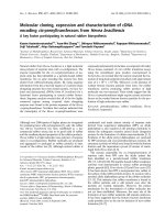
Natural rubber (NR) processing sector is an industry which produces raw materials used
for the manufacture of rubber industrial products (conveyor belts, rubber rollers, etc.),
automotive products (fan belts, radiator hoses, etc.), latex products (rubber gloves, toys
hygienic products, etc.) and many kinds of adhesives (see Figure 1.). The major users of
natural rubber are tire and footwear industries.
NR MANUFACTURING
NR PROCESSING
Rubber Sheet
LATEX
industrial products
(conveyor belts,
rubber rollers, etc.),
automotive products (fan
belts, radiator hoses, etc.),
Crepe Rubber
Crumb Rubber
rubber gloves, toys hygienic
p
roducts
Skim Latex
Latex Concentrate
Figure 1. Flow diagram of typical Natural Rubber (NR) processing and manufacturing
The raw material used for natural rubber processing is latex mainly tapped from rubber tree
(Hevea brasiliensis). Historically, natural rubber has been used since pre-columbian
period by ancient people in Mexico, Peru, and the Amazon Basin but its processing
industries were firstly developed in Brazil in 1870. However, due to the lack of labor
sources and limited land for rubber tree plantations in Brazil, the industries move to Asian
countries where land and labor sources are abundant. Therefore, it is reasonable that
nowadays Asia is the main source of natural rubber in the world, which account for around
94% of output in 2005 and the three largest natural rubber producing countries i.e.
Indonesia, Malaysia and Thailand account for around 72% of all natural rubber production
( rubber, 2007). Natural rubber factories are always
located around the plantation area, and they could be categorized from small scale to large
scale industries depending upon the size of rubber tree plantation.
As the demand of rubber products is increasing time to time, the existence and
development of natural rubber processing sectors become significantly important. Data
from International Rubber Study Group in
showed that global natural rubber production increased from 6,440 metric tons in 1996 to
8,821 metric tons in 2005, whereas its consumption increased from 6,110 metric tons in
1996 to 9,000 metric tons in 2005 (see Annex 1, Table 1.) It is estimated that world net
exports in 2010 are projected to grow by 1.3 percent annually to reach 5.5 million tons, 15
percent above the average of 1998-2000, with the bulk of the increase from Indonesia,
Vietnam and some smaller Asian countries (www.fao.org., 2007).
Raw material products from natural rubber processing sector provide huge benefits to
human beings as they are exploited to manufacture many kinds of important rubber goods.
However, environmental damages generated from this sector could become big issues.
Natural rubber processing sector consumes large volumes of water and energy and uses
large amount of chemicals as well as other utilities. It also discharges massive amounts of
2
wastes and effluents. The most common environmental issues are wastewater containing
chemicals and smell, hazardous waste, noise, and thermal emission. In order to reduce the
damage in the environment, waste abatement and management in natural rubber processing
sector should be handled properly.
This paper is presented to discuss in detail about natural rubber processing sector in terms
of its processing operations, major environmental issues generated from the sector and its
sources as well as its characteristics. In addition, waste treatment practices and
identification of CP potential in this sector are conferred. One case study referring to Xuan
Lap natural rubber processing in Vietnam is also discussed.
2. NATURAL RUBBER PRODUCTION PROCESSESS
The raw material used for the production of natural rubber is “white milky fluid” called
latex taken from the latex vessels of rubber trees, which can be categorized as field latex,
scrap, soil lump, and bowl lump. Chemically, latex consists of rubber, resins, proteins,
ash, sugar, and water. Verhaar (1973) mentioned that rubber content in the latex comes
from the trees is approximately 30 to 40%. Latex, which is a kind of biotic liquids, will be
deteriorated if it is not preserved by ammonia or sodium sulfite which is called
anticoagulant. Anticoagulants prevent latex from pre-coagulation. The kind of
anticoagulant used is depended upon the production process. Sodium sulfite is preferred if
crepe or sheet rubbers are to be made, but ammonia is more suitable for latex concentrate
In summary, the product of natural rubber can be broadly classified under two categories
i.e. dry and liquid rubber. Dry rubber refers to the grades, which are marketed in the dry
form such as rubber sheet, crepe rubber, and crumb rubber, whereas liquid rubber refers to
the latex concentrate production in which the field latex is separated into latex concentrate
containing about 60% dry rubber and skim latex with 4-6% of dry content. Skim latex is
produced as a byproduct during the preparation of latex concentrate. It has a dry rubber
content of only 3 to 7% and its dirt content is very low. Coagulation of skim latex can be
either spontaneously or by acid treatment. It is important that the ammonia content is kept
as low as possible. Further processing is the same as for smoked sheet. The processing of
miscellaneous latex also exists in some factories (see Annex 6, Figure 6.)
Referring to the whole steps in natural rubber processing, it is obvious that both dry and
wet processes are involved. Size reduction, digestion, washing, and drying are unit
operations involved in these processing activities. The step of washing consumes large
amount of water, so that wastewater generated from these processing operations mainly
comes from this step. Brief descriptions of processing of each type of natural rubber are
presented below.
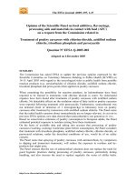
2.1. Processing of rubber sheet
Rubber sheet could be categorized as Air Dried Sheet (ADS) and Ribbed Smoked Sheet
(RSS). The main difference of ADS and RSS is on the method used for drying the sheet,
in which ADS exploits air, whereas RSS uses smoke provided in a smokehouse with the
temperature up to 60°C. The original type of smokehouses has been replaced by so-called
“Subur” smokehouses. The principle of the design of these houses is to eliminate as much
as possible manhandling of sheets. The smoking chambers are on ground level, so that
trolleys can be loaded with sheets in the factory and then transported by rail into the smoke
chambers. The smoking process in the “Subur” smokehouses is basically a continuous
process.
Rubber sheet processing is started from latex collection in the field. It is then diluted and
screened before the addition of formic acid for coagulation process. The wet sheet is
3
sheeted off to a thickness of about 3 mm and finally passes an embossed two roll mill. The
sheets are dried whether by air or in a smokehouse for about one week at temperatures.
The specific smell of the smoked sheets is caused by the wood and other organic materials
such as coconut shells used to produce the smoke. The sheets produced are finally
classified and packaged. The flow diagram of rubber sheet processing is presented in the
Annex 2, Figure 2.
2.2. Processing of Crepe rubber
Crepe rubber is made from latex field coagulum. In the production of crepe rubber from
latex, the raw material is prevented from coagulation by adding ammonia. After
transported to the factory, latex is filtered through a screen to remove coagulated rubber,
particles, or leaves. It is then transferred to mixing tank with stirring blade after determine
dry rubber content (DRC), latex is diluted with water to reduce DRC to 20 – 22%.
In the production of crepe rubber, there are three important steps. Diluted latex from
mixing tank is transferred to stationary coagulation troughs through movable throughs.
Acetic or formic acid solution (2%) is normally used to neutralize ammonia added in the
field for coagulation prevention and to reduce pH to 5.0 – 5.2, near the isoelectric point of
4.3. The second step is primary and secondary milling. After coagulation, water is added to
coagulation troughs to float up the coagulum. In water, coagulum is easy to move to
milling machine. After primary milling, slabs of coagulum is passed through pair of roller
of which the final one is grooved so as imprint on each the rib to increase the surface area
for drying. Each roller is equipped with water sprayers to wash away non rubber particles.
Then coagulum is cut into small, then it is dried by hot air and pressed. The flow diagram
of crepe rubber processing is presented in the Annex 3., Figure 3.
2.3. Processing of crumb rubber
This type of natural rubber product is relatively new, which in trade market it is known as
“technical specification rubber” (Setyamidjaja, 1993). There are some benefits of crumb
rubber processing i.e. the process is faster, the product is more clean and uniform, and the
appearance of product is more interesting. Raw materials used for making crumb rubber
can be field latex or low quality lump. The steps included in crepe rubber processing using
field latex are latex coagulation, milling, drying, bale pressing, and packing. Coagulation
process uses 1% formic acid plus 0.36% melase. Sodium bisulfate is usually added to the
coagulation mixture to get brighter end-product. If the raw material used is lump, the step
will be started by soaking and/or washing the lump, and then followed by hammer milling,
crepe formation, milling, drying, bale pressing, and packing. The flow diagram of crumb
rubber processing is presented in the Annex 4., Figure 4.
2.4. Processing of latex concentrate
Latex colleted from the field is pre-treated such as screen, wash and ammonia addition
before processing. After processing, the field latex is centrifuged. Because the disperse
phase (rubber) and the continuous phase (water mainly) differ in density, the concentrated
latex (60%) rubber is separate and is collected from the center of centrifuge bowl, whereas
skim, about 5% rubber, is taken from the outer edge of centrifuge bowl. The concentrate
latex is bulked, ammoniated and then stored. The skim latex is deammoniated, coagulated
with acid, creped and dried. The flow diagram of rubber sheet processing is presented in
the Annex 5., Figure 5.
4
3. ENVIRONMENTAL ISSUES OF NATURAL RUBBER
PROCESSING SECTOR
Despite the numerous benefits that are rendered to the modernization of this world by
natural rubber, the consequence of natural rubber processing has yet provide a serious
problem due to its highly polluted effluents. The rapid growth of this industry generates
large quantities of effluents coming from its processing operations which is really a big
problem because of its wastewater contains high biological oxygen demand and ammonia.
Without proper treatment, discharge of wastewater from rubber processing industry to the
environment may cause serious and long lasting consequences.
3.1. Major environmental problems
3.3.1. High concentration of BOD, COD, & SS
Wastewater discharged from latex rubber processing usually contains high level of BOD,
COD and SS (see Table 2). These characteristics vary from country to country due to
difference in raw latex and applied technique in the process. The main source of the
pollutants is the coagulation serum, field latex coagulation, and skim latex coagulation.
These compounds are readily biodegradable and this will result in high oxygen
consumption upon discharge of wastewater in receiving surface water.
Table 2. Typical characteristics of wastewater from rubber processing
Type of
processing
pH BOD COD SS TDS Sulfide
Ribbed smoked
sheet rubber
5.05 4,080 8,080 - 4,120 ND
Latex
concentrate
- Creaming
- Centrifuging
8.95
5.30
34,900
3,645
58,752
5,873
14,142
1,962
28,307
13,597
-
-
Crumb
6.8 137 464 303 804 -
Crepe
- Pale latex
- Estate
Brown
5.7
6.9
2,260
137
4,667
469
391
386
2,303
513
44
-
Note: All Parameters are expressed in mg/I, except pH.
Source: India Central Pollution Control Board, 2001
3.3.2. Acidic effluent
It is noted by Pandey et. al. (1990) that the effluent from latex rubber processing industries
is basically acidic in nature. Different extents of acid usage in the different factories
attribute to pH variation of different effluent. Due to the use of acid in latex coagulation,
the effluent discharged from latex rubber factories is acidic and re-dissolves the rubber
protein. The effluent comprises mainly of carbonaceous organic materials, nitrogen and
sulfate. The quantity of acid used for coagulation of the latex, specifically in skim latex
after centrifugation operation, is generally found to be higher than the actual requirement.
3.3.3. High concentration of ammonia and nitrogen compounds
The high concentration of ammonia presents in the latex concentrate effluent posed another
serious threat to the environment. Most of the concentrated latex factories in the South of
Thailand discharge treated wastewater that contains high level of nitrogen & ammonia to a
nearby river or canals leading to a water pollution problem. If high level of ammonia is
discharged to water bodies, it could lead to death of some aquatic organisms living in the
5
water. Land treatment system has been conducted to treat and utilize nitrogen in treated
wastewater from the concentrated latex factory.
3.3.4. High level of sulfate
The effluent from latex concentrate factories contains high level of sulfate which originated
from sulfuric acid used in the coagulation of skim latex. The high level of sulfate in this
process can cause problem in the biological anaerobic treatment system as high levels of H
2
S
will be liberated to the environment and generates malodor problem. The free H
2
S also
inhibits the digestion process, which gives lower organic removal efficiency (Yeoh et. al.,
1993).
3.3.5. High level of odor
The odor causing compound such as hydrogen sulfide, ammonia, amines, can be produced
by many of wastewater treatment process. Most odor of organic nature arises from the
anaerobic decomposition of compounds containing nitrogen and sulfur (Dague, 1972;
Henry, 1980). The odor is detectable even at extremely low concentrations and makes
water unpalatable for several hundred miles downstream from the rubber plants. The
problems presents varies considerably depending on the plant site, the raw material used,
and the number of intermediary product. Most rubber factories in Songkhla province have
been forced to use activated sludge process or aerated lagoon to prevent the bad smell from
the anaerobic condition.
Table 3. Gaseous concentration emission from latex processing
No. Process unit
NH
3
(mg/m
3
)
H
2
S
(mg/m
3
)
1
Reception tank 0.23 – 8.53 0.022 – 0.03
2
Coarse chopping 0.21 – 1.67 0.017 – 0.021
3
Cutting/Rolling 0,23 – 0.67 0.019 – 1.27
4
Granulating 0.18 – 0.53 0.018 – 0.024
5
Centrifuging 2.56 - 4.42 0.008 – 0.012
6
Drying 0.15 – 0.36 0.01 - 0.021
7
Packaging 0.19 – 0.25 0.005 - 0.016
Source: Environmental Monitoring Report, 2004 – Dau Giay and Long Thanh latex rubber
processing factories, Vietnam.
3.3.6. Favorite condition for pathogenic bacteria
A large population of bacteria also presents in the effluent discharged from the factories.
The type of bacteria found in rubber effluent are coliform, Streptococci and E.Coli. Most
of constituents of the effluent can act as substrate for the growth of these microorganisms
(Baskaran, 1980).
6
3.2. Pollution Norms
Table 4. Typical Wastewater/ Effluent Discharged per ton of Product
Product Effluent (m
3
)
Skim latex 25
Latex concentrate 18
Miscellaneous latex 35
Total flow rate 10
6
m
3
/year
Source: Vietnam Rubber Company, 2004
3.3. Wastewater pollution load (kg/ton)
Table 5. Wastewater pollution load
Parameter
Latex
concentrate
Skim
latex
Miscellaneous
latex
Crumb
rubber
Pale
latex
Estate
brown
latex
Flow 5 - 18 25 35 45 45 43
COD
32 - 140 180 75 21 210 20
BOD
20 - 74 105 45 6 101 6
TS
37 – 75 45 30 36 104 22
TN
4 – 11 6 1 2 1 1
N-NH
3
3 - 9 2 - 2 1 1
Source: Synthetic data from Vietnam and India Latex rubber Industry
4. WASTE TREATMENT PRACTICES
The waste treatment practices may change accordingly to the characteristics of effluent
discharges and allowable limitations. Waste treatment practices include practices for
wastewater treatment, air pollution control and solid management. Of all environmental
issues generated from this industry, wastewater is the major problem with a wide range of
effects on human health and environmental health. Air pollution and solid management are
not major problems hence in this paper we mainly focus on wastewater treatment practices.
4.1. Wastewater treatment practices
Wastewater collected from rubber processing factory contains a variety of substances as
well as the commercially important constituent, in this case rubber hydrocarbon. It contains
proteins, minerals, non-rubber hydrocarbons and carbohydrates. This wastewater has high
concentration of ammonia
,
BOD
5
, COD, Nitrate, Phosphorus as well as total solids.
Moreover, the wastewater from latex concentrate and skim crepe industry contains sulfate
which comes from sulfuric acid in the skimming process and in some processes produce
rather high content of zinc and cadmium. Wastewater treatment practices can be mentioned
as pollution abatement. Pollution abatement involves (a) in-plant control of waste and (b)
7
end-process treatment of wastewater. Some in-plant control measures can be introduced to
enable reduction in consumption of water, generation of pollutants and to increase the
efficiency of the end-of-process wastewater treatment.
4.1.1. In-plant control measures
In the crepe and crumb rubber units, in which field coagulum is processed, high required
water quantity is generally used for soaking and also the soaking time allowed is not
adequate. If the raw scrap rubber is properly soaked and primary dirt removal is done by
scrap-washer, the quantity of water consumed in milling can be reduced.
In the crumb units, wastewater from final milling can be collected separately from the
effluent of the other milling section and can be used either for soaking the scrap rubber or
for the first milling process. This is comparatively clean and the amount of reduction can
be up to 25% of the total water consumption.
In centrifuge machine bowl, washing is done at the interval of 3-4 hours to remove the
sludge. About 0.5% rubber is lost during this washing step. To reduce loss, washing step
can be done at two stages. The first washing which is more concentrated may be
segregated and collected in a separate tank and coagulated for recovery of the rubber lost
during washing. This will result in reduction of pollution load in the effluent. The
possibility of diverting this waste stream into the skim coagulation tank can also be
considered.
The quantity of acid used for coagulation of the latex, especially skim latex kit after
centrifugation stage is generally found to be higher than the actual requirement. The time
needed in coagulation tank is also less. The incomplete coagulation results in the loss of
rubber particles into the effluent along with the skim serum. The excess acid not only
causes acidic effluent but also re-dissolves the rubber protein and causes delay in
coagulation. Hence, it is suggested that proper acid concentration applied and sufficient
coagulation time should be provided to obtain more or less clear liquid after complete
coagulation. The skim latex if de-ammoniated before coagulation, acid requirement can be
reduced and the ammonia concentration in effluent may also be reduced. In the latex
process units the segregated first washing of the coagulum may be diverted to the skim
coagulum tank where after skim coagulum recovery, the effluent may join the other
wastewater streams.
4.1.2. End of process treatment
Basically wastewater treatment can be divided into pretreatment, primary treatment,
secondary treatment, and tertiary treatment.
Pretreatment
The rubber trap used for arresting suspended matters should have holding capacity of at
least 12 hours with proper baffles to induce continuous up and down flow pattern. If
designed properly, this can reduce suspended solids by 40 to 60%. The equalization tank
should have at least one day detention time. It is preferred to have two equalization tanks,
each of them with one day detention time.
Primary treatment
For a latex processing unit, effluent from the equalization tank to be sent for neutralization
and chemical treatment by alum and iron salt (about 200 mg/l). Combined wastewater of
latex process units also needs neutralization by using of lime and settling of suspended
solids by using of coagulants. The settler/clarifier should have adequate detention time for
removal of suspended solids. The sludge may be taken to sludge drying beds for
dewatering. The dewatering of sludge produced by primary clarifier is normally carried out
on belt or vacuum filters which raises the sludge consistency from 20 to 40%.
Secondary treatment
8
Following the primary treatment, the effluent should be subjected to the biological
treatment. If sufficient land area is not available, then the effluent after primary settling
may be subjected to an extended aeration activated sludge type biological treatment
process.
Before going for biological treatment, it must be ensured that:
(a) All the in-plant control measures are adopted,
(b) Primary treatment e.g. rubber trap equalization neutralization and clarification steps are
incorporated.
The above measures will reduce substantial quantity of pollutants particularly BOD and
suspended solids. The primary treated effluent can be treated in a secondary/biological
treatment unit. It is envisaged to render secondary treatment by adoption of extended
aeration activated sludge process. The biological treated effluents should be settled in a
secondary settling tank.
If there is no constraint of land, the biological treatment could be anaerobic followed by
aerobic pond system with the proper dimensions, holding capacity and adequate detention
time (10 to 15 days) for anaerobic pond followed by 5 to 10 days for aerobic ponding
system. The type of soil and proximity to the wastewater and ground water table condition
should be taken into consideration before going for these treatment systems. Protective
lining is recommended to eliminate any risk.
In place of the anaerobic-aerobic system, an oxidation ditch of detention time of 2-3 days
can also be considered as an alternative for treating the effluents of the crumb rubber unit.
Depending on the real conditions of countries and specific processes, some units of
wastewater treatment are modified and adjusted to have better efficiency. For example,
most of the latex concentrate factories in the South of Thailand discharge treated
wastewater that contains high level of nitrogen to a nearby river or canals leading to a
water pollution problem. Land treatment system is used to treat and utilize nitrogen in
treated wastewater from the concentrated latex factory. The land treatment system resulted
high removal efficiency for nitrogen (Rungruang, 1998).
In recent years, many studies were carried out to treat wastewater from this industry by
biological methods such as ASP (activated sludge process) and use of oxygenic
phototrophic bacteria for treating latex rubber sheet wastewater (Thongnuekhang and
Puetpaiboon, 2004). These studies aim at improving the efficient treatment of wastewater
from this industry and contribute to partially reduce the emission of toxic gases into the
environment.
Tertiary treatment
The remaining components after primary and secondary treatment are residual SS, residual
BOD, odor and hydrocarbon. Tertiary treatment designed to remove these components are
generally carbon adsorption, massive lime treatment and foam separation, mainly for
treatment of Residual Refractory Organics. The flow diagram of treatment system adopted
presently given in Annex 8., Figure 7.
4.2. Air pollution control
In production process, a mixture of poisonous gases is generated from coagulation of
rubber and latex. It should be controlled and reduced by activated carbon treatment.
Chimney gases should be controlled technically, otherwise it might affect the growth of
agricultural plants in the fields.
Besides, foul smell due to wastewater drainage is a problem and it is difficult to control. It
can be reduced by applying in-plant measures or cleaner production such as reducing the
amount of wastewater generated from the process and separating wastewater from the latex
immediately when discharged. Most rubber factories in Songkhla province, Thailand have
9
been forced to use activated sludge process or aerated lagoon to prevent the bad smell from
the anaerobic condition.
Air pollution control is related to wastewater treatment methods. Hence, air pollution
control can be obtained by controlling and treating wastewater from production process.
5. IDENTIFICATION OF CP POTENTIAL IN NATURAL LATEX
RUBBER PROCESSING
A closed look reveals that rubber industry consumes large volumes of water, uses a lot of
chemicals and other utilities and discharges enormous amounts of wastes and effluents.
The few cleaner production assessments and implementation programs carried out in many
countries has shown tremendous benefits. Some of them are lesser usage of chemicals,
efficiency in energy and utilities including water, improvement in productivity and
profitability, lesser loads and volumes of effluent discharged to the neighborhood, better
image and relationship with employees internally and with the neighborhood externally.
Rubber Tapping and Transportation
Usage of traditional coconut shell as the cup for latex collection gives a large cup lump
increasing the scrap crepe. This should be replaced by a plastic bowl and the traditional
galvanized iron bucket is replaced by plastic buckets.
The addition of chemicals to the field latex is still a problem and training of tapers and
other personnel seems to be the main option available. The transportation of the field latex
by mild steel bowlers adds rust to latex. A coating of epoxy is very effective to eliminate
rust contamination of latex.
Coagulation
A simple partitioning of the coagulation tank using wooden planks will be very effective
instead of cutting the coagulum to size by a knife as in tradition. This saves labor involved
and the blocks are of uniform size, which produces uniform edged laces at milling.
Skim Coagulation
In centrifugation unit, the scrum water contains about 1% rubber which is usually
coagulated using sulfuric acid. The addition of ammonia in the field as well as in the
factory prior to centrifugation results in high usage of acid for skimming and causes many
problems in final treatment of effluent. To get the most effective latex formulation and
chemical dosing at field and in the factory through controlled trials is the most appropriate
solution to the problem which is complicated and time consuming. The long-term benefits
of this solution are very attractive. Before skim coagulation, the de-ammoniation of
effluent helps to reduce usage of sulfuric acid.
In all latex concentrate factories the scrum water from latex, centrifuge wash water and
bowler wash water is discharged as one stream. The segregation of these streams can help
to reduce final treatment cost and possibility of recycling of the wash water with a little
treatment for selected uses.
Energy Consumption
The uniform edged laces reduced the milling needs and blankets and bundles formed took
lesser time. In the dryer tower the internal partitioning and systematic passing of hot air
from chamber to chamber improved the drying efficiency.
Scrum Water
The serum water has many nutrients and other substances, which can be of high
commercial value. Trials are being conducted to use serum water as a liquid fertilizer.
10
6. CASE STUDY: XUAN LAP NATURAL RUBBER PROCESSING,
VIETNAM
A natural rubber processing factory (Xuan Lap factory) has the following parameters:
6.1. Cost and Investment (See Table 6.)
Table 6. Cost and investment of Xuan Lap natural rubber factory
Items Unit Value
Investment cost
From domestic USD
3,256,510
From foreign source -
-
Construction cost
Cost for factory construction and
installing machineries
USD
2,875,678
Cost for constructing wastewater
treatment plant
USD
365,892
Cost for installing others includes
environment protection equipments
ventilation, ear cap, muffler, etc
USD
14,940
Compensation cost (if any) for land
clearance
USD
none
Production cost
USD/yr
18,161,292
Maintenance cost
USD/yr
25,368
Depreciation cost
USD/yr
51,753
Operation cost of wastewater treatment
plant (should be more specific in cost
such as:
- chemical usage,
- power consumption,
- man power required,
- Others
USD/yr
USD/yr
USD/yr
USD/yr
59,008
16,956
27,236
13,277
1,539
Maintenance cost of WWTP
USD/yr
11,056
Total cost
18,308,477
Turnovers
USD/yr
21,890,547
Profits
3,582,070
Scale of the factory
Small scale
Production capacity Tons of product/year
11,000
Number of labor labor
142
The factory operates three main processes i.e. concentrated latex, skim latex, and
miscellaneous latex
6.2. Environmental issues related to the operation of the factory
1. Air pollution: mainly is H
2
S arises from raw latex, NH
3
from the process.
However, they can be considered as minor problems.
2. Solid waste (See Table 7.)
11
Table 7. Solid waste from natural rubber processing
Type of solid
waste
Latex
concentrate
process
Skim latex
process
Miscellaneous
latex process
Other sources
Miscellaneous
latex
√ √ √
Packages
containing
chemical and
oil
√ √
√
waste glove,
nylon bag
containing
chemical
√ √ √ √
Paper
√
Organic matter
√
3. Wastewater (see Table 8)
Table 8. Characteristic of wastewater from individual process
Parameters Unit Concentrated
process
Skim latex
process
Miscellaneous
process
Domestic
Flow rate m
3
/d 520 – 570 150 – 170 660 – 700 6 – 10
pH 5.9 - 6.65 6 - 6.5 6.5 - 6.7 6.4 - 6.8
Temperature
0
C 26 - 30 26 - 30 27 - 30 25 - 30
BOD
5
mg/l 5,560 – 5,800 3,000 – 3,200 1,500 – 1,700 250 - 400
COD mg/l 9,450 – 12,000 6,500 – 7,200 2,500 – 3,000 500 - 520
SS mg/l 2,050 – 2,200 2,500 – 2,700 1,000 – 1,200 220 - 230
Total N mg/l 250 - 450 132 – 150 30 – 40 40 - 45
Total P mg/l 23 – 30 - - 8 - 10
NH3-N mg/l 200 – 400 70 – 100 2 - 5 -
Characteristics of combined waste water are as follow (see Table 9):
Table 9. Characteristics of combined wastewater
Parameters Unit Value
Flow rate m
3
/d 1,300 – 1,450
pH 6 - 6.5
Temperature
0
C 25 - 30
BOD
5
mg/l 1,800 – 2,400
COD mg/l 3,000 – 4,000
SS mg/l 650 – 1,000
Total N mg/l 150 – 200
Total P mg/l 4 – 8
NH3-N mg/l 100 - 150
12
6.3. Opportunity for Waste segregation
The effluent from all processes have similar constituent i.e. high BOD and COD load, high
SS concentration which is contributed from uncoagulated latex; high concentration of
Nitrogen, and basically in acidic condition.
Especially, the liquor discharged directly from the process has very high concentration, i.e.
5,000 – 6,000 mg/l of BOD and 9,500 – 12,000 mg/l of COD for centrifuge process. This
effluent is difficult to be treated directly, so they should be diluted by combining with other
process effluents e.g. miscellaneous process and rinse/washout water that has lower
loading before transported to the treatment plant.
However, wastewater from miscellaneous and general washout usually contains certain
amount of sand and grit, so that they should be separated for grit removal before
combining with wastewater from other process. If not, the grit removed from the treatment
plant would contain high amount of latex and serum and that would lead to unpleasant
odor when dumping it due to high degradable of latex and serum.
6.4. Wastewater treatment layout
The lay out of wastewater treatment plant is proposed as described in Annex 8, Figure 7
based on the following criteria:
- Characteristic of the effluent
- Available resources for wastewater treatment plant (land area available, cost)
- Terrain, location and reception source
- Operation regulation
The Major O&M issues related to wastewater treatment plants could be:
- High level of odor from NH
3
and H
2
S
- Acidic condition leads to corrosion in the equipment
- The factory is only operated during a certain season in a year, i.e. about 7 months/year.
This will lead the problem in frequently start up the treatment system and effect the
treatment efficiency.
6.5. Material Balance
Although the factory is operated three processes, this case study only focus on the latex
concentrate processing to carry out the material balance in order to assess process
performance and to find out potential for improvement.
Step 1: Determining Inputs
Amount of consumption Item of chemical
consumption
Kg/ton of product
Kg/d
Ammonia (NH
4
-
) 11.05 Ammonia (NH
4
-
)
Zinc oxide (ZnO) 0.075 Zinc oxide (ZnO)
Lauric Acid 0.175 Lauric Acid
Di-Ammonium Hydrogen
Phosphate (NH
4
)
2
HPO
4
2.3
Di-Ammonium Hydrogen
Phosphate (NH
4
)
2
HPO
4
Total 13.6 Total
13
Step 2: Recording water usage
Unit operation m
3
/ton of field latex m
3
/day
Reception (screening)
Rinse water
0.05
5
Preservation
Process water
0.12
13
Storage and transportation
Rinse water
1.3
138
Reception tank
Process water
Rinse water
0.1
0.23
11
25
Dilution tank
Process water
Rinse water
0.7
0.53
74
56
Centrifugation
Rinse water
0.42
45
Stabilization
Process water
Rinse water
0.06
0.47
6
50
Packaging
Prewash water
0.58
61
General Floor and Plant
wash water
0.66 70
Total
Process water
Rinse water
General Wash down
Total
0.98
3.58
0.66
22.7
104
380
70
554
Step 3: Quantifying process outputs
Unit operation Wastewater By-product/
Waste reused
Atmospheric Solid waste
Preservation
Rinse water NH
3
gas
Storage and
transportation
Rinse water
Reception
(screening)
Rinse water NH
3
gas Leaf, rubber
tree skin, etc…
containing latex
Centrifugation
Process water
Rinse water
Skim latex NH
3
gas
Stabilization
Rinse water NH
3
gas, H
2
S
Packaging
Spilled centrifuged
latex
- - -
14
Step 4: Accounting for wastewater
Average Flows, strengths and Pollution Loads of Strong Liquors
Wastewater Flow BOD COD SS Total N
m
3
/d
pH mg/l kg/d
mg/l kg/d
mg/l kg/d
mg/l kg/d
Centrifugation 158 6.25
5,565
897
9,450
1,493
2,050
324
250
40
Combine wastewater flows, strengths and Pollution loads
BOD COD SS Total N Wastewater Flow
(m
3
/day)
mg/l kg/d mg/l kg/d mg/l kg/d mg/l kg/d
Strong liquors
158 5,565
897
9,450
1493
2050
324
250
40
Rinse
water/General
washdown
412 430 177 510 210 102 42 36 15
Total
570 - 1,056 - 1,073 - 366 - 55
Step 5: Accounting for gaseous emission (assumed that it is not considered)
Step 6: accounting for By-Product/Solid waste
- Screening: tree skin, leaf contain latex but in a very small amount, dumped onsite
- By-Product:
+ Coagulated latex: reused for block rubber process, not considerable
+ Skim latex: 7,740 kg/day
Step 7: Material balance
Inputs kg/d
Field latex 106,000
Chemical 476,2
Water 554,000
Total 660,476.2
Overall Centrifugation process
Output kg/d
Centrifuged latex 35,000
Skim latex 7,740
Gaseous Not considered as a major output
Wastewater 570,000
Total 612,740
15
Step 8: Evaluating the material balance and Suggestion
After balancing input and output of the process and refining the material balance, it is
showed that there are 47,736.2 kg/d (7.2% of input) lost from the process. This may
happen due to:
- Leaking of field latex on the way from harvesting field to the factory, and from
subsequence steps in the process;
- Wastewater is leaking from the process; or there are problems in wastewater
collecting system, especially is rinse water. A part of it may run to the storm water
collecting system.
- Percentage of converting field latex to latex concentrate and skim latex is quite low
due to low performance of centrifuge machine, so that large amount of latex is washing out
through wastewater.
To overcome these problems, such measures are proposed i.e.:
+ Check the field latex collecting step to minimize leaking of field latex
+ Repair or replace centrifuge machine to improve centrifugation efficiency
+ Examine wastewater collecting system
6.6. Waste sampling and monitoring
6.6.1. Water quality
a. Location to take sample: influent and effluent of wastewater treatment plant
b. Parameters: pH, BOD
5
, COD, SS, ammonia, N, P, Zn, Al, Mn
6.6.2. Air quality
a. Location to take samples: main entrance gate, raw material intake area, WWTP,
chemical storage house, workshop areas, stack of drying room and downwind areas 200
and 500 meters away from factory.
b. Parameters: PM, CO, NOx, SO
2
, NH
3
, H
2
S, and noise
6.6.3. Applied Standard
Following standards of Vietnam (TCVN):
Discharge: 5945-1995 (class B)
Emission: 5937-1995 (class B), 5938-1995, 5939-1995
6.4. Frequency of monitoring: 2 times/year (at production season)
16
REFERENCES
1. Anil, K.B., Malcolm, M.H., H.A., Benarey, et al. (1994). Rubber products
manufacturing technology . Marcel Dekker, Inc.
2. Applied Technique and Production Company (2004). Environmental Impact Assessment
report for Xuan Lap latex rubber processing company. Dong Nai province, Vietnam
3. Asia, I. O. and Akporhonor, E. E (2007). Characterization and physicochemical
treatment of wastewater from rubber processing factory. Retrieved March 2007, from
Department of Chemistry, Ambrose Alli University, P. M. B. 14 Ekpoma, and
Department of Chemistry, Delta State University, Abraka, Nigeria. Website:
/>strial%20latex%20wastewater.pdf
4. Central Pollution Control Board. CPCB Divisions - Activities. Pollution Control
Implementation - III Divisions. Natural Rubber Processing Industry. Website:
/>5. Dong Nai Rubber Company (2004), Monitoring report Xuanlap natural rubber, Dong
Nai province, Vietnam.
6. Duangporn Kantachote, Salwa Torpee, Kamontam Umsakul (2005). The potential use of
anoxygenic phototrophic bacteria for treating latex rubber sheet wastewater. Retrieved
June 24, 2005, from Faculty of Science, Prince of Songkla University, Thailand.
Website: />7. ., 2007
8. rubber, 2007
9. IRSG in (2007)
10. Peiris, S. (2000). Experience of Cleaner Production elementation in rubber industry
and potential for future in Sri Lanka. Retrieved March 20, 2007, from Sena Peiris,
Cleaner Production Professionals Association of Sri Lanka. Website:
/>eiris.pdf
11. Rungruang, N. (1998). Treatment of natural rubber processing wastewater by
combination of ozonation and activated sludge process. (Masters research study No.
EV-98-32, Asian Institute of Technology, 1998). Bangkok: Asian Institute of
Technology
12. Setyamidjaja, D. (1993). Karet: Budidaya dan Pengolahan. Penerbit Kanisius.
Yogyakarta.
13. Thonglimp, V., Srisuwan, G., and Jkaew (2005). Treatment of industrial latex
wastewater by activated sludge system. Retrieved May 2005, from Prince of Songkla
University, Faculty of Engineering, Department of Chemical Engineering, Hat-Yai,
Songkla 90110, Thailand. Website:
/>strial%20latex%20wastewater.pdf
17
14. Thongnuekhang, V. and Puetpaiboon, U. (2004). Nitrogen removal from concentrated
latex wastewater by land treatment. Retrieved 22 March 2004, from The Joint Graduate
School of Energy and Environment, King Mongkut’s University of Technology
Thonburi, Bangkok, 10140 Thailand, Department of Civil Engineering, Faculty of
Engineering, Prince of Songkla University, Hat Yai, Songkhla, 90112 Thailand.
Website: />wastewater.pdf.
15. Verhaar, G. (1973). Processing of Natural rubber. Food and Agriculture Organization
of the United Nation
16. C., Visvanathan. (2007). Industrial Waste Abatement and Management. (Lecture note,
Course No. ED78.20, School of Environment, Resources and Development). Bangkok:
Asian Institute of Technology.
18
ANNEXES
19
ANNEX 1
Table 1. World natural rubber production and consumption
Year
Production (1000 tons) Consumption (1000 tons)
1996 6,440 6,110
1997 6,470 6,460
1998 6,850 6,570
1999 6,872 6,646
2000 6,764 7,383
2001 7,242 7,334
2002 7,303 7,627
2003 7,976 8,003
2004 8,639 8,579
2005 8,821 9,000
Source: IRSG in (2007)
20
ANNEX 2
Soil
rubber
0.5%
Scrap
2.5%
Latex
97%
Left over
latex in cup
and basket
From rubber plantation
water
Waste water
Lump + foam
2 %
Filter
Mixing tank
Filter
Coagulation
tank
Milling
Smoking
Drying
Sortation
and packing
Waste from
cutting
Water
Water
Water
Water
Off crepe Compo Compo Standard sheet 89%
Figure 2. Flow diagram of rubber smoke sheet processing
21
ANNEX 3
Ammonia
0.1%
Coagulation
Formic acid
2%
Milling
Latex reception
(Screen and dilution)
Preservation
Washing
Field latex
Lump
(Bowl lump, soil lump)
WW
WW
WW
Cutting
WW
Drying
T= 110 – 120
o
C
Export Pressing, Packing and Storage
Figure 3. Diagram of crepe rubber processing
22
ANNEX 4
Latex
Coagulation
Lump
(100%)
Pre-breaking
Hammer milling
Filter
Calendar hammer milling
Drying
Weighing
Bale pressing
Packaging
Storage
Figure 4. Flow
diagram of crumb rubber processing
23
ANNEX 5
WW
Ammonia
0.1%
Centrifugation
Concentrated latex
Storage
Centrifugation
Export
Skim latex
Coagulation
Crushing
Milling
Cutting
Drying
Pressing, Packing and Storage
Latex reception (screen)
Ammonia
98%
DRC & NH3 determination
WW
Sulfuric acid
WW
WW
Preservation
T= 110 – 120
o
C
WW
Ammonia
98%
Field latex
Figure 5. Diagram of latex concentrate processing
24
ANNEX 6
Soaking basin
(receiving,
classifying, soaking
and washing out)
Miscellaneous
latex
Coarse pressing and
cutting
Chopping small bits
Sheet flattening
Fine chopping
Arranging, draining
Drying
Weighing
Sheet flattening
Granulating
Compressing
Packing
Storage
Wastewater
Solid waste
Wastewater
Solid waste
Wastewater
Solid waste
Wastewater
Solid waste
Wastewater
Solid waste
Wastewater
Solid waste
Wastewater
Solid waste
Wastewater
Leftover heat
Leftover heat
Solid waste
Water
Electricity
Water
Electricity
Water
Electricity
Water
Electricity
Water
Electricity
Water
Electricity
Water
Electricity
Electricity
Electricity
Wood Pallet
Plastic bag
Figure 6. Diagram of miscellaneous rubber processing
25