A MIPS 32-bit Single-Cycle CPU pptx
Bạn đang xem bản rút gọn của tài liệu. Xem và tải ngay bản đầy đủ của tài liệu tại đây (1.99 MB, 35 trang )
A MIPS 32-bit Single-
Cycle CPU
G r o u p 6
L e M i n h H o a n g
L e H o n g T h a n g
L u o n g T r a n N h a t T r u n g
Instructor: Ho Viet Viet
LA: Nguyen Van Hieu
- 1 -
A MIPS 32-bit Single-Cycle CPU
Group 6 | Le Minh Hoang | Le Hong Thang | Luong Tran Nhat Trung
Table of Contents
I. ABSTRACT - 3 -
II. LAB OBJECTIVES - 3 -
III. LAB REQUIREMENTS - 3 -
IV. OVERVIEW OF THE IMPLEMENTATION: - 4 -
FUNCTION:………………. - 4 -
THE INTERGER ARITHMETIC-LOGICAL INSTRUCTIONS: - 4 -
THE MEMORY REFERENCE INSTRUCTIONS: - 5 -
THE BRANCH AND JUMP INSTRUCTION: - 6 -
V. DESIGNING THE MAIN CONTROL UNITS AND A DATAPATH: - 7 -
ALU CONTROL AND CONTROL MODULE: - 7 -
CONTROL SIGNALS TABLE - 8 -
*ENHANCEMENT 1 - 10 -
BUILDING A DATA PATH: - 11 -
*ENHANCEMENT 2 - 12 -
Overall RTL Viewer………… - 13 -
VI. DESIGN MODULE - 14 -
PC MODULE……………… - 14 -
EXTEND MODULE……… - 15 -
MUX RegDst MODULE - 16 -
SHIFT LEFT 2 MODULE - 18 -
CHECK_ZERO MODULE - 20 -
MUX 4Addrto1 MODULE - 22 -
InstructionMem MODULE - 23 -
DATA MEMORY MODULE: - 24 -
VII. STIMULATION RESULT OF MIPS SINGLE CYCLE DATA PATH - 25 -
ADD INSTRUCTION:…………. - 26 -
BRANCH ON NOT EQUAL INSTRUCTION - 27 -
JUMP INSTRUCTION:…… - 28 -
JUMP REGISTER INSTRUCTION: - 29 -
LOAD AND STORE WORD INSTRUCTION: - 30 -
- 2 -
A MIPS 32-bit Single-Cycle CPU
Group 6 | Le Minh Hoang | Le Hong Thang | Luong Tran Nhat Trung
SUB INSTRUCTION:……… - 31 -
SET ON LESS THAN INSTRUCTION: - 32 -
XORI INSTRUCTION:…… - 33 -
VIII. CONCLUSION: - 34 -
IX. REFERENCE: - 34 -
- 3 -
A MIPS 32-bit Single-Cycle CPU
Group 6 | Le Minh Hoang | Le Hong Thang | Luong Tran Nhat Trung
**Note: Since this lab contains some work we have done in the two previous labs, we are not going to
present them in detail here
I. ABSTRACT
The purpose of this design problem is building up the data path and constructing a simple version of
32-bit MIPS Single-Cycle CPU. The CPU instructions to be implemented are the memory-reference
instruction LW & SW, the arithmetic –logical XORI, ADD, SUB, SLT, and BNE, J, JR function. The
system takes PC address as an input and converts it into instruction to implement the functions. The lab
report includes the data path single cycle of MIPS overview, the simulation and Verilog code using the
Quartus and ModelSim program.
II. LAB OBJECTIVES
For this lab3 you are to design a simple 32-bit MIPS Single-Cycle CPU. The CPU instructions to
be implemented are LW, SW, J, JR, BNE, XORI, ADD, SUB, and SLT. Chapter 4 will give some
examples of how architectures are put together, and will be useful as you design your own CPU. For
this CPU, you will use your two previous lab projects (the register and the ALU) so you will need
to have these fully functional before proceeding to work on your CPU
III. LAB REQUIREMENTS
1. Write
MIPS
32
-bit Single-Cycle CPU
and TestBench on your own.
2. ALL logic must be gate level, structural except that
the
control
logic
for CPU
can
be
done
behaviorally
3. All gates must have at most 4 input
4. All gates have a delay of 50ps
- 4 -
A MIPS 32-bit Single-Cycle CPU
Group 6 | Le Minh Hoang | Le Hong Thang | Luong Tran Nhat Trung
IV. OVERVIEW OF THE IMPLEMENTATION:
FUNCTION:
The lab constructs the simple version of the process sufficient to implement an instruction set like
MIPS. In the MIPS instruction, there are the integer arithmetic-logical instructions, the memory
reference instructions and the branch instructions.
THE INTERGER ARITHMETIC-LOGICAL INSTRUCTIONS:
In the lab, the arithmetic-logical instructions or R-type include add, sub, slt class.
- ADD rd, rs, rt: Reg[rd] = Reg[rs] + Reg[rt]. The instruction will read data in register rs and rt. After
that they will be added and written to the register rd.
- SUB rd, rs, rt: Reg[rd] = Reg[rs] – Reg[rt]. The instruction will read data from register rs and rt.
After that the result from rs sub rt will be written into register rd.
- SLT rd, rs, rt: The set on less than instruction which will compare the value in register rs and rt. In
the case the value of rs is less than rt‟s one, the value in register rd equal 1, and 0 in the opposite case.
As we can see from the data path, the register file will read two indicated register operands. After that,
the data will be transferred into the ALU to perform arithmetic or logical operation such as add or sub.
The result of ALU will move to the register file again to write output into the chosen register.
- 5 -
A MIPS 32-bit Single-Cycle CPU
Group 6 | Le Minh Hoang | Le Hong Thang | Luong Tran Nhat Trung
THE MEMORY REFERENCE INSTRUCTIONS:
In the lab, the memory-reference instructions include load word(lw) and store word(sw).
- LW rt, imm16(rs): Reg[rt] = Mem[Reg[rs] + Sign_ext(Imm16)]. The instruction will load word from
memory to register rt.
- SW rt, imm16(rs): Mem[Reg[rs] + Sign_ext(Imm16)] = Reg[rt]. The instruction will store word from
register to memory.
As we can see from the data path, the register file will read data then add to the 16bit signed offset field
contained in the instruction. If the instruction is a store, the value to be stored must also be read from
register file. In the case instruction is a load, the value read from memory must be written into the
register file in the specified register. In the data path, there is a data memory, which can read and write
data with the control signals. In addition, the sign-extend will be constructed to perform the 16 bit
offset to a 32 bit signed value.
- 6 -
A MIPS 32-bit Single-Cycle CPU
Group 6 | Le Minh Hoang | Le Hong Thang | Luong Tran Nhat Trung
THE BRANCH AND JUMP INSTRUCTION:
In the lab, the branch and jump instruction include the branch on not equal (bne), jump (j) and jump
register (jr).
- BNE rs, rt, imm16: if (Reg[rs] != Reg[rt]) PC = PC + 4 + Sign_ext(Imm16)<<2 else PC = PC + 4.
The instruction will compare the value in register rs and rt. In the case the value of rs does not equal
one in rt, the PC will jump to address of PC +4 Sign_ext(Imm16) after shift left 2.
- J target: PC = { PC[31:28], target, 00 }. The jump instruction will take the PC move into the target
address.
- JR rs: PC = Reg[rs]. The jump register instruction jumps to the address stored in the rs register.
As we can see from the data path, there is extra mux2to1 and output jump of control module, which
determine PC to jump or not. The addition multiplexor is used to choose between the jump target and
either the branch target or the sequential instruction following this one. The instruction need more 1
module shift left 2 to convert the 26bit instruction to 28bit instruction.
- 7 -
A MIPS 32-bit Single-Cycle CPU
Group 6 | Le Minh Hoang | Le Hong Thang | Luong Tran Nhat Trung
V. DESIGNING THE MAIN CONTROL UNITS AND A DATAPATH:
ALU CONTROL AND CONTROL MODULE:
The ALU control determines the operation of ALU including ADD, SUB, SLT (set on less
than), XOR, BNE (branch on not equal).
In addition, the Control module will output the control signal for register file, data memory or
multiplexors in the system.
- 8 -
A MIPS 32-bit Single-Cycle CPU
Group 6 | Le Minh Hoang | Le Hong Thang | Luong Tran Nhat Trung
CONTROL SIGNALS TABLE
Function
Format
Op code
instruction[31-26]
Funct
instruction[5-0]
ALU
function
ALU ctrl
lw
I
100011
xxxxxx
add
00
sw
I
101011
xxxxxx
add
00
bne
I
000101
xxxxxx
sub
10
xori
I
001110
xxxxxx
xor
01
addi
I
001000
xxxxxx
add
00
j
J
000010
xxxxxx
xxx
xx
jr
R
000000
001000
add
00
Add
R
000000
100000
add
00
Sub
R
000000
100010
sub
10
slt
R
000000
101010
slt
11
Function
RegDst
MemtoReg
ALUOp
MemWrite
ALUSrc
RegWrite
Zero_Sign
Jump
JumpReg
Branch
lw
1
1
00
0
1
1
1
0
0
0
sw
0
0
00
1
1
0
1
0
0
0
bne
1
0
10
0
0
0
1
0
0
1
xori
0
0
01
0
1
1
0
0
0
0
addi
0
0
00
0
1
1
1
0
0
0
j
1
0
xx
0
x
0
1
1
0
0
jr
1
0
00
0
x
0
1
0
1
0
add
1
0
00
0
0
1
1
0
0
0
sub
1
0
10
0
0
1
1
0
0
0
slt
1
0
11
0
0
1
1
0
0
0
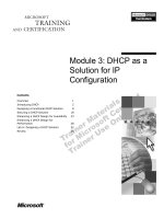
The picture below is RTL viewer of Control module in Quartus II.
- 9 -
A MIPS 32-bit Single-Cycle CPU
Group 6 | Le Minh Hoang | Le Hong Thang | Luong Tran Nhat Trung
D
ENA
PRE
CLR
Q
0
1
0
0
1
0
D
ENA
PRE
CLR
Q
0
1
0
D
ENA
PRE
CLR
Q
D
ENA
PRE
CLR
Q
IN[5 0]
OUT[63 0]
DECODER
=
A[5 0]
B[5 0]
EQUAL
=
A[5 0]
B[5 0]
EQUAL
=
A[5 0]
B[5 0]
EQUAL
=
A[5 0]
B[5 0]
EQUAL
D
ENA
PRE
CLR
Q
D
ENA
PRE
CLR
Q
D
ENA
PRE
CLR
Q
D
ENA
PRE
CLR
Q
D
ENA
PRE
CLR
Q
D
ENA
PRE
CLR
Q
SEL[3 0]
DATA[3 0]
OUT
SELECTOR
SEL[1 0]
DATA[1 0]
OUT
SELECTOR
SEL[3 0]
DATA[3 0]
OUT
SELECTOR
SEL[3 0]
DATA[3 0]
OUT
SELECTOR
SEL[3 0]
DATA[3 0]
OUT
SELECTOR
SEL[3 0]
DATA[3 0]
OUT
SELECTOR
D
ENA
PRE
CLR
Q
ALUOp[0]$latch
ALUOp[0]~2
ALUOp[0]~3
ALUOp[1]$latch
ALUOp[1]~4
ALUOp[1]~5
ALUSrc$latch
ALUSrc~0
Branch$latch
Decoder0
Equal0
6' h08
Equal1
6' h20
Equal2
6' h22
Equal3
6' h2A
Jump$latch
JumpReg$latch
MemtoReg$latch
MemWrite$latch
RegDst$latch
RegWrite$latch
Selector3
3' h1
Selector5
1' h0
Selector11
3' h1
Selector17
3' h1
Selector18
3' h3
Selector19
3' h3
WideOr2
WideOr4
WideOr5
WideOr6
WideOr7
WideOr8
Zero_Sign$latch
RegDst
MemWrite
ALUSrc
RegWrite
Zero_Sign
Jump
JumpReg
Branch
ALUOp[1 0]
instr31_26[5 0]
instr5_0[5 0]
WideOr0
MemtoReg
- 10 -
A MIPS 32-bit Single-Cycle CPU
Group 6 | Le Minh Hoang | Le Hong Thang | Luong Tran Nhat Trung
*ENHANCEMENT 1
From the knowledge above, we have to design two separate control modules, which costs time,
registers and memory. Also, from the lab 2, we design the 32-bit ALU, which can only perform
4 operation (add, sub, xor, slt). Therefore, we enhance this situation by combining these two
modules into one. Specifically, instead of taking only Instruction [31-26] as an input in the
Control module, it will have Instruction [5-0] as an input also. In addition, we put 2 more
control signals, which are Zero_Sign and JumpReg
- 11 -
A MIPS 32-bit Single-Cycle CPU
Group 6 | Le Minh Hoang | Le Hong Thang | Luong Tran Nhat Trung
BUILDING A DATA PATH:
Below is the datapath in textbook
- 12 -
A MIPS 32-bit Single-Cycle CPU
Group 6 | Le Minh Hoang | Le Hong Thang | Luong Tran Nhat Trung
*ENHANCEMENT 2
1. Mux 4 To 1 is formed by combining 3 muxes. The new mux has three control signals (jump,
jumpreg, and branch), 4 input (Bne Address, Jump Address, PC4 Address, JumpReg Address)
and one output is PCin
2. The sign-extend is transformed into “extend” to make its task easier, which is controlled by
signal Zero_Sign
3. From the above table, we can see that all of instruction implemented in lab 3 just use the simple
performance of ALU (add, sub, xor, slt), so that we combine two control modules into one
control module.
4. Finally, we don‟t use Zero flag from the ALU, because we only know whether two register
equal to each other or not after taking subtraction from two register. Therefore, we make one
more module CheckZero, which just take a smaller time than ALU to check if the two register
is equal. With this module, lab 4 may become easier when dealing with data hazard.
- 13 -
A MIPS 32-bit Single-Cycle CPU
Group 6 | Le Minh Hoang | Le Hong Thang | Luong Tran Nhat Trung
Overall RTL Viewer
Here is the RTL Viewer of MIPS 32-bit Single-Cycle CPU from Quartus II
- 14 -
A MIPS 32-bit Single-Cycle CPU
Group 6 | Le Minh Hoang | Le Hong Thang | Luong Tran Nhat Trung
VI. DESIGN MODULE
**Note: There are some modules, which is described in previous labs, such as regfile,
ALU, and add32bit. Thus, in this report we do not explain about them.
PC MODULE
Our PC module is just a 32-bit register (described in lab 1), which take PCin as an input and PCout as a
output.
- 15 -
A MIPS 32-bit Single-Cycle CPU
Group 6 | Le Minh Hoang | Le Hong Thang | Luong Tran Nhat Trung
EXTEND MODULE
We need a unit to sign-extend the 16-bit offset field in the instruction to a 32-bit signed value.
In our case, if zero-sign is 0, we will extend zero for whatever sign; and if it is 1, we will extend the
sign with 1, or 0. Below is the simulation of this module
We test the module Zero_Sign = 0. It is extended with zeros to make it a 32-bit output
Now, we test with Zero_Sign =1, the sign of the input is „1‟, or „negative‟. So, it is extended some more
ones to make a 32-bit output
Finally, we test with Zero_Sign = 1, but now the sign of the input is „0‟, or „positive‟. So,it is
extended some more zeros to make a 32-bit output.
Now, we use Quartus to get the RTL viewer of this module
- 16 -
A MIPS 32-bit Single-Cycle CPU
Group 6 | Le Minh Hoang | Le Hong Thang | Luong Tran Nhat Trung
MUX RegDst MODULE
This multiplexor is used to choose instr [20-16] (rt), or instr [15-11] (rd).
In the below simulation, you can see that with RegDst = 1, we choose the second input (00110) (Rd); and with
RegDst = 0, we choose the first input (00011) (Rt)
- 17 -
A MIPS 32-bit Single-Cycle CPU
Group 6 | Le Minh Hoang | Le Hong Thang | Luong Tran Nhat Trung
Now, we use Quartus to get the RTL viewer of this module
- 18 -
A MIPS 32-bit Single-Cycle CPU
Group 6 | Le Minh Hoang | Le Hong Thang | Luong Tran Nhat Trung
SHIFT LEFT 2 MODULE
This module is used for the jump target address, which is obtained by shifting the lower 26 biys of the
jump instruction left 2 bits, effectively adding 00 as the low-order bits, and then concatenating the
upper 4 bits of PC+4 as the high-order bits, thus yielding a 32-bit address. Also, this module is used for
“bne” in shifting left sign_extend (imm16) <<2
- 19 -
A MIPS 32-bit Single-Cycle CPU
Group 6 | Le Minh Hoang | Le Hong Thang | Luong Tran Nhat Trung
Below is the simulation of this module. Obviously, there are two more zeros added at the low-end.
(Since two module is almost the same so that we use one simulation for the two)
Now, we use Quartus to get the RTL viewer of the first Shift_Left_2
Now, we use Quartus to get the RTL viewer of the second Shift_Left_2
- 20 -
A MIPS 32-bit Single-Cycle CPU
Group 6 | Le Minh Hoang | Le Hong Thang | Luong Tran Nhat Trung
CHECK_ZERO MODULE
This module is used to check if the result of a certain operation is zero or not. If the output is 1, the
result is zero; otherwise, it is not zero.
Breakthrough: instead of putting the ZeroFlag module inside ALU like we did in Lab 2, we make this
task faster by putting outside. Specifically, we check the inputs first. If they are equal, Zero is 1. If they
are not, Zero is 0
Below is the simulation of this module. Will the two inputs be equal, the result is Zero; otherwise, the
result is not zero.
- 21 -
A MIPS 32-bit Single-Cycle CPU
Group 6 | Le Minh Hoang | Le Hong Thang | Luong Tran Nhat Trung
Now, we use Quartus to get the RTL viewer of this module
- 22 -
A MIPS 32-bit Single-Cycle CPU
Group 6 | Le Minh Hoang | Le Hong Thang | Luong Tran Nhat Trung
MUX 4Addrto1 MODULE
This module is used to combine all muxes on the right upper. Below is to show the improvement
specifically
Jump
JumpReg
BranchZero
Output (PCin)
1
0
0
JumpAddr
0
1
0
JumpRegAddr
0
0
1
BneAddr
0
0
0
PC4Addr
- 23 -
A MIPS 32-bit Single-Cycle CPU
Group 6 | Le Minh Hoang | Le Hong Thang | Luong Tran Nhat Trung
InstructionMem MODULE
The module is given, which has the input: 32-bit address and output: 32-bit instruction. The module
give us the instruction will be executed.
Below is its simulation.
- 24 -
A MIPS 32-bit Single-Cycle CPU
Group 6 | Le Minh Hoang | Le Hong Thang | Luong Tran Nhat Trung
DATA MEMORY MODULE:
The module is provided, which has the input : write data, address, and control signal MemWrite, output
: ReadData. The module will respond for write data into the indicated address through memory.
Below is its simulation