APJ 1000 maintenance manual
Bạn đang xem bản rút gọn của tài liệu. Xem và tải ngay bản đầy đủ của tài liệu tại đây (421.44 KB, 10 trang )
Maintenance manual of APJ1000 piezoelectric valve
I.
Precautions for use
There are some attention points related to construction of APJ1000 jetting valve and piezoelectric
driven principle:
1. During the procession of using valve, successive tape-ranked dots (连连连连连连连) shouldn’t be
too much that 1000 dots/ time is its base number. Interval of successive times should be at
least 5s.
Reason: cleaning glue successively will produce more heat for successive dot in cool state
which would make inside temperature to increase suddenly and may burn the inside
piezoelectric stack in serious condition.
2. High frequency operation successively using in a long time must be added air-cooling and
heat dissipation.
Reason: decreasing temperature can make input more stably and prevent ceramic be burned
by high temperature. Decreasing 0.02~0.01Mpa is enough. Cooling gas must be filtered.
3. When the valve is opened, slightly tighten the nozzle and seal.
Reason: piezoelectric only needs small output displacement to realize dispensing, because
screwing too tight will condense a part of output displacement which will decrease its
performance.
4. All seal ring of inside valve is forbidden to be soaked in corrosivity cleaning solution, including
ethyl alcohol:
Reason: the seals are engineering plastic material, soaked in the organic solvent will destroy
the seal structure and size to influence its sealing.
5. When valve that end cleaning is not applicable to use, every wear parts should not be
installed in valve directly and need to be put together to take care of.
Reason: prevent nozzle or other parts blocked in exposed circumstance.
6. Prohibit hot plug
Reason: when valve power on, plugging the signal line on valve body may lead overshoot and
cause damage to valve which may give irreversible damage to dispensing performance.
7. If the equipment is not applicable at some time, you’d better to close the power of controller.
Reason: If equipment has power but don’t work for a long time, it will not operate so fluently
when it open again and parameter needs to be reset usually. Turning off the power and
opening it again, the equipment can be used again with previous parameter.
II.
APJ1000 parts analysis diagram
III. Maintenance
After using APJ1000 dispensing valve each time, it needs appropriate cleaning and maintenance
to prolong its service life, and keeps it high dispensing quality and consistency at the same time.
After long time using, valve needs complete maintenance which usually once week.
3.1 Fluid contact parts cleaning
The main part of maintenance of APJ1000 jetting valve is fluid contact parts cleaning in case after
long time using that fluid solidify or block in chamber. The steps of maintenance and cleaning are
as follows:
(1) Close feeding pressure, turn air pressure to 0, cutting power line of controller and remove
signal line of controller heat connect line and so on.
(2) Dismount APJ1000 jetting valve from fixed panel of platform.
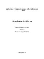
(3) Screw off nozzle cage in overlooking clockwise direction by nozzle spanner. As shown in the
figure 7-1;
Nozzle spanner
Nozzle cage
Figure 2.1 the direction of screwing nozzle cage
(4) Carefully take off nozzle cage, nozzle, nozzle-head fastener and O ring from the chamber; use
the end of three convex foot of spanner to screw off nozzle-head fastener from nozzle cage;
as shown in the figure 2-2. The surface of unscrewing nozzle is wiped up by a cotton swab.
Then use 1.5 nozzle cleaner guide glue in the inner channel. Lastly, clean glue on inner wall of
chamber by cotton swab.
O-ring
Guidance spanner
Nozzle cage
Nozzle
Figure 2.2 dismounting and cleaning of nozzle
(5) a. dismount seal ring on nozzle-head fastener, as shown in the figure 2-3;
b. clean nozzle: guide glue in pore of nozzle by odontorine and blow out left glue by
pneumatic gun. Repeat this operation to assure there has no glue in pore of nozzle; the
method of odontorine unchoking nozzle cage is as follows; at last, nozzle and nozzle-head
fastened are put in ultrasonic utensil or designated solvent to wash by water at least 10 min;
odontorine
nozzle
Figure 2.3 The method of unchoking nozzle
(6) Use 2.5mm hex wrenches to unscrew M3 socket head cap screw to separate fluid channel
and valve. Fluid channel should be taken down carefully. Because seal ring has some force of
friction, after unscrew to an extent, fluid channel needs to be hardly pulled down. As the
Figure2.4;
Figure 6.4 chamber dismounting
(7) After dismantle liquid channel, erect liquid channel and Luer stand need to be split off by
2.5mm hex wrenches; then the Luer taper is unscrewed by the other end of dispensing
spanner. Clean inside wall which has liquid by 1.5mm nozzle cleaner and hairbrush, after
then, Luer taper, Luer stand and erect liquid are all put in ultrasonic equipment at least 10
minutes. Specific information is as the following Figure 2.5. All dismantling O-ring, sealing
packing and spring ring ( ( ( ( mustn’t be soaked by cleaning solvent, including ethyl
alcohol;
Luer stand
Luer taper
O ring
M4 screw
Sealing gasket/ heat insulated pad
Erect fluid channel
The specific cleaning process is as follows:
Spring ring
Hair brush
1.5 nozzle cleaner
Figure 2.6 cleaning method of fluid channel
(8) Procession of dismantling of firing pin: when it is necessary, use the end of two convex foot
of guide to wretch dismantle firing pin. Show as the Figure2.7. The surface of firing pin is
cleaned by dust-free cloth which is dipped in cleaning solution.
Guidance of firing pin
Guidance spanner
Firing pin
2.2 Assembling after cleaning
1. Put nozzle into inner groove of nozzle-head fastener, then screw nozzle-head fastener into
nozzle cage by triangle spanner. To ensure nozzle will not loss in nozzle cage.
Figure 2.8
2. Install guidance into cleaning firing pin and smear lubricate in the position which firing pin
and guidance contact (our company provide it) to make movement of firing pin smoothly
and softly. Finally install module of firing pin and guidance into valve.
3. Put auxiliary ceramics plate into ceramics heat resisting sheet.
4. Install vertical flow channel into it and tighten bolt.
5. Screw nozzle module into the glue position and ensure it will not be screwed too deep,
because firing pin will be moved down after valve powered on.
Note: When valve that end cleaning is not applicable to use, every wear parts should not
be installed in valve directly and need to be put together to take care of in case nozzle fall
accidentally or bump into sharp parts to damage nozzle.