Mechanical preparation of root canals: shaping goals, techniques and means potx
Bạn đang xem bản rút gọn của tài liệu. Xem và tải ngay bản đầy đủ của tài liệu tại đây (5.24 MB, 47 trang )
Mechanical preparation of root
canals: shaping goals, techniques
and means
MICHAEL HU
¨
LSMANN, OVE A. PETERS & PAUL M.H. DUMMER
Preparation of root canal systems includes both enlargement and shaping of the complex endodontic space together
with its disinfection. A variety of instruments and techniques have been developed and described for this critical stage of
root canal treatment. Although many reports on root canal preparation can be found in the literature, definitive scientific
evidence on the quality and clinical appropriateness of different instruments and techniques remains elusive. To a large
extent this is because of methodological problems, making comparisons among different investigations difficult if not
impossible. The first section of this paper discusses the main problems with the methodology of research relating to root
canal preparation while the remaining section critically reviews current endodontic instruments and shaping techniques.
Introduction
Preparation of the root canal system is recognized as
being one of the most important stages in root canal
treatment (1, 2). It includes the removal of vital and
necrotic tissues from the root canal system, along with
infected root dentine and, in cases of retreatment, the
removal of metallic and non-metallic obstacles. It aims
to prepare the canal space to facilitate disinfection by
irrigants and medicaments. Thus, canal preparation is
the essential phase that eliminates infection. Prevention
of reinfection is then achieved through the provision of
a fluid-tight root canal filling and a coronal restoration.
Although mechanical preparation and chemical disin-
fection cannot be considered separately and are
commonly referred to as chemomechanical or biome-
chanical preparation the following review is intended to
focus on the mechanical aspects of canal preparation
cavity. Chemical disinfection by means of irrigation and
medication will be reviewed separately in this issue.
History of root canal preparation
Although Fauchard (3), one of the founders of modern
dentistry described instruments for trepanation of
teeth, preparation of root canals and cauterization of
pulps in his book ‘Le chirurgien dentiste’, no
systematic description of preparation of the root canal
system could be found in the literature at that time.
In a survey of endodontic instrumentation up to
1800, Lilley (4) concluded, that at the end of the 18th
century ‘ . . . only primitive hand instruments and
excavators, some iron cauter instruments and only very
few thin and flexible instruments for endodontic
treatment had been available’. Indeed, Edward May-
nard has been credited with the development of the
first endodontic hand instruments. Notching a round
wire (in the beginning watch springs, later piano wires)
he created small needles for extirpation of pulp tissue
(5, 6). In 1852 Arthur used small files for root canal
enlargement (6–9). Textbooks in the middle of the
19th century recommended that root canals should be
enlarged with broaches: ‘But the best method of
forming these canals, is with a three- or four-sided
broach, tapering to a sharp point, and its inclination
corresponding as far as possible, with that of the fang.
This instrument is employed to enlarge the canal, and
give it a regular shape’ (10). In 1885 the Gates Glidden
drill and in 1915 the K-file were introduced. Although
standardization of instruments had been proposed in
30
Endodontic Topics 2005, 10, 30–76
All rights reserved
Copyright r Blackwell Munksgaard
ENDODONTIC TOPICS 2005
1601-1538
1929 by Trebitsch and again by Ingle in 1958, ISO
specifications for endodontic instruments were not
published before 1974 (10).
The first description of the use of rotary devices seems
to have been by Oltramare (11). He reported the use of
fine needles with a rectangular cross-section, which
could be mounted into a dental handpiece. These
needles were passively introduced into the root canal to
the apical foramen and then the rotation started. He
claimed that usually the pulp stump was removed
immediately from the root canal and advocated the use
of only thin needles in curved root canals to avoid
instrument fractures. In 1889 William H. Rollins
developed the first endodontic handpiece for auto-
mated root canal preparation. He used specially
designed needles, which were mounted into a dental
handpiece with a 3601 rotation. To avoid instrument
fractures rotational speed was limited to 100 r.p.m.
(12). In the following years a variety of rotary systems
were developed and marketed using similar principles
(Fig. 1).
In 1928 the ‘Cursor filing contra-angle’ was devel-
oped by the Austrian company W&H (Bu¨rmoos,
Austria). This handpiece created a combined rotational
and vertical motion of the file (Fig. 2). Finally,
endodontic handpieces became popular in Europe with
the marketing of the Racer-handpiece (W&H) in 1958
(Fig. 3) and the Giromatic (MicroMega, Besanc¸on,
France) in 1964. The Racer handpiece worked with a
vertical motion, the Giromatic with a reciprocal 901
rotation. Further endodontic handpieces such as the
Endolift (Kerr, Karlsruhe, Germany) with a combined
vertical and 901 rotational motion and similar devices
were marketed during this period of conventional
endodontic handpieces. All these devices worked with
limited, if any, rotation and/or a rigid up and down
motion of the instrument, which were all made from
stainless steel. The dentist could only influence the
rotational speed of the handpiece and the vertical
amplitude of the file movement by moving the hand-
piece (10, 13).
A period of modified endodontic handpieces began
with the introduction of the Canal Finder System (now
distributed by S.E.T., Gro
¨
benzell, Germany) by Levy
(14). The Canal Finder was the first endodontic
handpiece with a partially flexible motion. The
amplitude of the vertical file motion depended on the
rotary speed and the resistance of the file inside the root
canal and changed into a 901 rotational motion with
increasing resistance. It was an attempt to make the
root canal anatomy or at least the root canal diameter
one main influencing factor on the behaviour of the
instrument inside the canal. The Excalibur handpiece
(W&H) with laterally oscillating instruments or the
Fig. 1. Endodontic Beutelrock-bur in a handpiece with a
flexible angle from 1912. Reprinted from (13) by
permission by Quintessence Verlag, Berlin.
Fig. 2. Cursor-handpiece (W&H) from 1928. Reprinted
from (13) by permission by Quintessence.
Mechanical preparation of root canals
31
Endoplaner (Microna, Spreitenbach, Switzerland) with
an upward filing motion were further examples of
handpieces with modified working motions (10, 13).
Table 1 summarizes available instruments and hand-
pieces for engine-driven root canal preparation.
Richman (15) described the use of ultrasound in
endodontics but it was mainly the work of Martin &
Cunningham (16) in the 1970s that made ultrasonic
devices popular for root canal preparation. The first
ultrasonic device was marketed in 1980, the first sonic
device in 1984 (13). Since 1971 attempts have been
made to use laser devices for root canal preparation and
disinfection (17). Additionally, some non-instrumental
or electro-physical devices have been described such as
ionophoresis in several different versions, electrosurgi-
cal devices (Endox, Lysis, Munich, Germany) (18) or
the non-instrumental technique (NIT) of Lussi et al.
(19), using a vacuum pump for cleaning and filling of
root canals.
Instruments made from nickel–titanium (NiTi), first
described as hand instruments by Walia et al. (20), have
had a major impact on canal preparation. NiTi rotary
instruments introduced later use a 3601 rotation at low
speed and thus utilize methods and mechanical
principles described more than 100 years ago by
Rollins. While hand instruments continue to be used,
NiTi rotary instruments and advanced preparation
techniques offer new perspectives for root canal
preparation that have the potential to avoid some of
the major drawbacks of traditional instruments and
devices.
Goals of mechanical root canal
preparation
As stated earlier, mechanical instrumentation of the
root canal system is an important phase of root canal
preparation as it creates the space that allows irrigants
and antibacterial medicaments to more effectiveley
eradicate bacteria and eliminate bacterial byproducts.
However, it remains one of the most difficult tasks in
endodontic therapy.
In the literature various terms have been used for this
step of the treatment including instrumentation,
preparation, enlargement, and shaping.
The major goals of root canal preparation are the
prevention of periradicular disease and/or promotion
of healing in cases where disease already exists through:
Removal of vital and necrotic tissue from the main
root canal(s).
Creation of sufficient space for irrigation and
medication.
Preservation of the integrity and location of the
apical canal anatomy.
Avoidance of iatrogenic damage to the canal system
and root structure.
Facilitation of canal filling.
Avoidance of further irritation and/or infection of
the periradicular tissues.
Preservation of sound root dentine to allow long-
term function of the tooth.
Techniques of root canal preparation include manual
preparation, automated root canal preparation, sonic
and ultrasonic preparation, use of laser systems, and
NITs.
Ingle (21) described the first formal root canal
preparation technique, which has become known as
the ‘standardized technique’. In this technique, each
Fig. 3. Racer-handpiece (W&H) from 1959. Reprinted
from (13) by permission by Quintessence.
Hu¨lsmann et al.
32
Table 1. Summary of currently available systems for engine-driven systems for root canal preparation and their
respecive properties
Handpiece Manufacturer Mode of action
Conventional systems
Racer Cardex, via W&H, Bu¨rmoos, Austria Vertical movement
Giromatic MicroMega, Besanc¸on, France Reciprocal rotation (901)
Endo-Gripper Moyco Union Broach,
Montgomeryville, PA, USA
Reciprocal rotation (901)
Endolift Sybron Endo, Orange, CA, USA Vertical movement1reciprocal rotation (901)
Endolift M 4 Sybron Endo Reciprocal rotation (301)
Endocursor W&H Rotation (3601)
Intra-Endo 3 LD KaVo, Biberach, Germany Reciprocal rotation (901)
Alternator Unknown Reciprocal rotation (901)
Dynatrak Dentsply DeTrey, Konstanz, Germany Reciprocal rotation (901)
Flexible systems
Excalibur W&H Lateral oscillations
(2000 Hertz, 1.4–2 mm amplitude)
Endoplaner Microna, Spreitenbach, Switzerland Vertical motion1free rotation
Canal-Finder-System S.E.T., Gro
¨
benzell, Munich Vertical movement (0.3–1 mm)1free
rotation under friction
Canal-Leader 2000 S.E.T. Vertical movement (0.4–0.8 mm)1partial
rotation (20–301)
Intra-Endo 3-LDSY KaVo Vertical motion1free rotation
IMD 9GX HiTech, unknown 3601 – rotation with variable, torque-dependent
rotational speed (min 10/min)
Sonic systems
Sonic Air 3000 MicroMega
Endostar 5 Medidenta Int, Woodside, NY, USA 6000 Hz
Mecasonic MicroMega
MM 1400 Sonic Air MicroMega
Yoshida Rooty W&H 6000 Hz
MM 1500 Sonic Air MicroMega 1500–3000 Hz
Ultrasonic systems
Cavi-Endo Dentsply DeTrey Magnetostrictive 25 000 Hertz
Piezon Master EMS, Nyon, Switzerland Piezoceramic 25 000–32 000Hz
ENAC OE 3 JD Osada, Tokyo, Japan Piezoceramic 30 000 Hz
Mechanical preparation of root canals
33
instrument was introduced to working length resulting
in a canal shape that matched the taper and size of the
final instrument. This technique was designed for
single-cone filling techniques.
Schilder (1) emphasized the need for thorough
cleaning of the root canal system, i.e., removal of all
organic contents of the entire root canal space with
instruments and abundant irrigation and coined the
axiom ‘what comes out is as important as what goes in’.
He stated that shaping must not only be carried out
with respect to the individual and unique anatomy of
each root canal but also in relation to the technique of
and material for final obturation. When gutta-percha
filling techniques were to be used he recommended
that the basic shape should be a continuously tapering
funnel following the shape of the original canal; this was
termed as the ‘concept of flow’ allowing both removal
of tissue and appropriate space for filling. Schilder
described five design objectives:
I. Continuously tapering funnel from the apex to the
access cavity.
II. Cross-sectional diameter should be narrower at
every point apically.
III. The root canal preparation should flow with the
shape of the original canal.
IV. The apical foramen should remain in its original
position.
V. The apical opening should be kept as small as
practical.
And four biologic objectives:
I. Confinement of instrumentation to the roots
themselves.
Table 1. Continued
Handpiece Manufacturer Mode of action
Piezotec PU 2000 Satelec, Merignac, France Piezoceramic 27 500 Hz
Odontoson Goof, UsserdMlle, Denmark Faret rod 42 000 Hz
Spacesonic 2000 Morita, Dietzenbach, Germany
NiTi systems
LightSpeed Lightspeed, San Antonio TX, USA Rotation (3601)
ProTaper Dentsply Maillefer, Ballaigues, Switzerland Rotation (3601)
K 3 Sybron Endo Rotation (3601)
ProFile 0.04 and 0.06 Dentsply Maillefer Rotation (3601), taper 0.4–0.8
Mity-Roto-Files Loser, Leverkusen, Germany Rotation (3601), taper 0.02
FlexMaster VDW, Munich Germany Rotation (3601), taper 0.02/0.04/0.05
RaCe FKG, La-Chaux De Fonds, Switzerland Rotation (3601)
Quantec SC, LX Tycom, now: Sybron Endo Rotation (3601)
EndoFlash
n
KaVo Rotation (3601)
NiTiTEE Loser Rotation (3601)
HERO 642 MicroMega Rotation (3601), taper 0.02–0.06
Tri Auto ZX Morita, Dietzenbach, Germany 3601-rotation1auto-reverse-mechanism and
integrated electrical length determination
GT Rotary Dentsply Maillefer Rotation (3601), taper 0.04–0.12
n
Initially available as stainless-steel instruments.
Hu¨lsmann et al.
34
II. No forcing of necrotic debris beyond the foramen.
III. Removal of all tissue from the root canal space.
IV. Creation of sufficient space for intra-canal medica-
ments.
Challenges of root canal preparation
Anatomical factors
Several anatomical and histological studies have de-
monstrated the complexity of the anatomy of the root
canal system, including wide variations in the number,
length, curvature and diameter of root canals; the
complexity of the apical anatomy with accessory canals
and ramifications; communications between the canal
space and the lateral periodontium and the furcation
area; the anatomy of the peripheral root dentine
(22–25) (Fig. 4). This complex anatomy must be
regarded as one of the major challenges in root canal
preparation and is reviewed in detail elsewhere in this
issue.
Microbiological challenges
Both pulp tissue and root dentine may harbor
microorganisms and toxins (26–33). A detailed de-
scription of the complex microbiology of endodontic
infections lies beyond the scope of this review, this issue
recently has been reviewed by Ørstavik & PittFord
(34), Dahlen & Haapasalo (35), Spa
˚
ngberg & Haapa-
salo (36) and others.
Iatrogenic damage caused by root
canal preparation
Weine et al. (37, 38) and Glickman & Dumsha (39)
have described the potential iatrogenic damage that can
occur to roots during preparation with conventional
steel instruments and included several distinct prepara-
tion errors:
Zip
Zipping of a root canal is the result of the tendency of
the instrument to straighten inside a curved root canal.
This results in over-enlargement of the canal along the
outer side of the curvature and under-preparation of
the inner aspect of the curvature at the apical end point.
The main axis of the root canal is transported, so that it
deviates from its original axis. Therefore, the terms
straightening, deviation, transportation are also used to
describe this type of irregular defect. The terms
‘teardrop’ and ‘hour-glass shape’ are used similarly to
describe the resulting shape of the zipped apical part of
the root canal (Fig. 5A, B).
Elbow
Creation of an ‘elbow’ is associated with zipping and
describes a narrow region of the root canal at the point
Fig. 4. Morphology of the apical par ts of the root canal
systems of a maxillary pre-molar and canine as described
by Meyer (24). Reprinted from (13) by permission by
Quintessence.
Fig. 5. (A, B) Simulated root canals in plastic blocks
before and following preparation clearly demonstrate the
genesis of straightening and creation of zip and elbow.
Mechanical preparation of root canals
35
of maximum curvature as a result of the irregular
widening that occurs coronally along the inner aspect
and apically along the outer aspect of the curve. The
irregular conicity and insufficient taper and flow
associated with elbow may jeopardize cleaning and
filling the apical part of the root canal (Fig. 6A, B).
Ledging
Ledging of the root canal may occur as a result of
preparation with inflexible instruments with a sharp,
inflexible cutting tip particularly when used in a
rotational motion. The ledge will be found on the
outer side of the curvature as a platform (Fig. 7), which
may be difficult to bypass as it frequently is associated
with blockage of the apical part of the root canal. The
occurrence of ledges was related to the degree of
curvature and design of instruments (40–42).
Perforation
Perforations of the root canal may occur as a result of
preparation with inflexible instruments with a sharp
cutting tip when used in a rotational motion (Fig. 8).
Perforations are associated with destruction of the root
cementum and irritation and/or infection of the
periodontal ligament and are difficult to seal. The
incidence of perforations in clinical treatment as well as
in experimental studies has been reported as ranging
from 2.5 to 10% (13, 43–46). A consecutive clinical
problem of perforations is that a part of the original
root canal will remain un- or underprepared if it is not
possible to regain access to the original root canal
apically of the perforation.
Strip perforation
Strip perforations result from over-preparation and
straightening along the inner aspect of the root canal
curvature (Fig. 9). These midroot perforations are
again associated with destruction of the root cementum
and irritation of the periodontal ligament and are
difficult to seal. The radicular walls to the furcal aspect
of roots are often extremely thin and were hence
termed ‘danger zones’.
Outer widening
First described by Bryant et al. (47) ‘outer widening’
describes an over-preparation and straightening along
Fig. 7. Ledging at the outer side of the root canal
curvature. Reprinted by permission of Quintessence.
Fig. 6. Elbow formation and apical zipping in a curved
maxillary canine. Reprinted by permission from Urban &
Fischer, Munich.
Hu¨lsmann et al.
36
the outer side of the curve without displacement of the
apical foramen. This phenomenon until now has been
detected only following preparation of simulated canals
in resin blocks.
Apical blockage
Apical blockage of the root canal occurs as a result of
packing of tissue or debris and results in a loss of
working length and of root canal patency (Fig. 10). As a
consequence complete disinfection of the most apical
part of the root canal system is impossible.
Damage to the apical foramen
Displacement and enlargement of the apical foramen
may occur as a result of incorrect determination of
working length, straightening of curved root canals,
over-extension and over-preparation. As a consequence
irritation of the periradicular tissues by extruded
irrigants or filling materials may occur because of the
loss of an apical stop. Clinical consequences of this
occurrence are reviewed elsewhere in this issue.
Besides these ‘classical’ preparation errors insufficient
taper (conicity) and flow as well as under- or over-
preparation and over- and underextension have been
mentioned in the literature.
Criteria for assessment of the quality
of root canal preparation
When analyzing the quality of root canal preparation
created by instruments and techniques several para-
meters are of special interest, particularly their cleaning
Fig. 8. Perforation of a curved root canal.
Fig. 9. Strip perforation at the inner side of the
curvature.
Fig. 10. Apical blockage by dentine debris. Reprinted
with kind permission from Quintessence, Berlin.
Mechanical preparation of root canals
37
ability, their shaping ability as well as safety issues. A
detailed list of potential criteria for the assessment of
the quality of root canal instruments or preparation
techniques is presented in Table 2.
Methodological aspects in assessment
of preparation quality
Over recent decades a plethora of investigations on
manual and automated root canal preparation has been
published. Unfortunately, the results are partially
Table 2. Summary of possible criteria for assess-
ment of techniques and instruments for root canal
preparation, including motors and handpieces
Disinfection
Reduction of the number of microorganisms
Removal of infected dentine
Improvement of irrigation
Unprepared areas
Cleanliness of root canal walls debris
Smear layer
Preparation shape
Longitudinal
Straightening, deviation
Displacement and enlargement of the apical foramen
Zips and elbows
Taper, conicity
Flow
Over/underextension
In cross-sections
Diameter
Circumferential/cross-sectional shape
Over/under-preparation
Fins and recesses
Increase in canal area
Danger of perforation into the furcation
Canal axis movement
Three-dimensional
Straightening and transportation
Changes in volume
Canal axis movement
Safety issues
Instrument fractures
Ledges
Perforations
Table 2. Continued
Excessive dentine removal
Apical blockage
Loss of working length
Extruded debris and/or irrigant
Temperature increase
Working time
Efficacy
Handling
Maintenance of digital/manual tactility
Adjustment of a stopper for length control
Insertion of instruments into handpiece
Programming the motor
Accessibility to the posterior region
Visualization during preparation
Assortment of files, quality of files, size designation
Integrated irrigation, type and amount of irrigant
Noise and vibrations of the handpiece or motor
Ergonomy and mobility of the device
Costs
Instruments
Motor or handpiece
Life-span of instruments and motor
Hu¨lsmann et al.
38
contradictory and no definite conclusions on the
usefulness of hand and/or rotary devices can be drawn,
Major deficiencies of studies on quality of root canal
preparation include:
While currently available hand instruments have
been used for almost a century, no definitive mode
of use has emerged as the gold standard. However,
the Balanced force technique (48) may be cited as
such a gold standard for ex vivo and clinical studies
(49–51).
In the majority of experimental studies published in
the literature only a small number of rotary systems
or rotary techniques are investigated and compared.
Only few studies include a comparison of four (39,
50, 52–56), five (57), or six and more (13, 45, 46,
58–65) devices and techniques.
In the majority of these published studies only some
of the parameters listed in Table 2 were investigated,
thus allowing only limited conclusions on a certain
device, instrument or technique. The majority of
studies still focus on preparation shape in a long-
itudinal plane, whereas the number of studies on
cleaning ability remains small. This probably is
because of the fact, that the investigation of both
cleaning and shaping is difficult to perform in one
single experimental procedure and in any case
requires two different evaluations. Data on working
time and working safety are usually not collected in
separate experiments but rather are a side-product of
investigations designed for other purposes.
A wide variety of experimental designs and metho-
dological considerations as well as of evaluation
criteria does not allow a comparison of the results of
different studies even when performed with the
same device or technique.
Many publications do not include sufficient data on
sample composition, operator experience and train-
ing, calibration before assessment, e.g., photo-
graphs or electron micrographs, and on
reproducibility of the results (inter- and intra-
examiner agreement).
It has been criticized that in many studies prepara-
tion protocols modified by the investigators have
been introduced and evaluated rather than the
preparation protocol as suggested by the manufac-
turer. This might result in inadequate use of
instruments and techniques and lead to misleading
results and conclusions.
Evaluation of post-operative root
canal cleanliness
Post-operative root canal cleanliness has been investi-
gated histologically or under the SEM using long-
itudinal (13, 65, 66) and horizontal (67–69) sections of
extracted teeth. In horizontal sections remaining
predentine, pulpal tissue and debris may be stained
and the amount of remaining tissue and debris
measured quantitatively (68, 69). The use of horizontal
sections allows a good investigation of isthmuses and
recesses but loose debris inside the canal lumen may be
lost during sectioning. As well contamination of the
root canal system with dust from the saw blades may
occur.
The use of longitudinal sections allows nearly
complete inspection of both halves of the entire main
root canal. Lateral recesses and isthmuses are difficult to
observe. From a technical point of view it is difficult to
section a curved root, therefore it has been proposed
first to cut the root into horizontal segments which
then may be split longitudinally (13, 70). In horizontal
sections great care must be taken to avoid contamina-
tion during the sectioning process, which may be
prevented by insertion of a paper point or a gutta-
percha cone.
For the assessment of root canal cleanliness in the
majority of the studies two parameters have been
evaluated: debris and smear layer.
Debris may be defined as dentine chips, tissue
remnants and particles loosely attached to the root
canal wall.
Smear layer has been defined by the American
Association of Endodontists’ glossary ‘Contemporary
Terminology for Endodontics’ (71): A surface film of
debris retained on dentine or other surfaces after
instrumentation with either rotary instruments or
endodontic files; consists of dentine particles, remnants
of vital or necrotic pulp tissue, bacterial components
and retained irrigant.
Further criteria may be the reduction of bacteria and
the removal/presence of tissue, both of which are more
difficult to assess but clinically more relevant.
Scores
The standard technique for the evaluation of post-
operative root canal cleanliness is the investigation of
root segments under the SEM. For this purpose several
Mechanical preparation of root canals
39
different protocols have been described. Some of these
studies are only of descriptive nature (53, 54, 72–75),
others use predefined scores. These scoring systems
include such with three scores (76–80), four scores (55,
64, 81–85), five scores (13, 65, 86–88), or even seven
scores (89). From the majority of these publications it
does not become clear, whether the specimens had
been coded and the examiner blinded before the SEM
investigation, preventing the identification of the
preparation instrument or technique under the SEM.
Furthermore, only in a few studies was the reproduci-
bility of the scoring described (65).
Additionally, the magnifications used under the SEM
differ widely, in some studies respective data are not
presented at all or different magnifications were used
during the investigation. A certain observer bias may
occur under the SEM when working with higher
magnifications, as only a small area of the root canal
wall can be observed. This area may be adjusted on the
screen by chance or be selected by the SEM operator. It
is a common finding that most SEM operators tend to
select clean canal areas with open dentinal tubules
rather than areas with large bulk of debris.
Not surprisingly, in most studies root canal cleanli-
ness has been demonstrated to be superior in the
coronal part of the root canal compared with the apical
part (13). Therefore an evaluation procedure specifying
the results for different parts of the root canal seems
preferable.
Evaluation of post-operative root
canal shape
The aim of studies on post-operative root canal shape is
to evaluate the conicity, taper and flow, and main-
tenance of original canal shape, i.e., to record the
degree and frequency of straightening, apical transpor-
tation, ledging, zipping and the preparation of
teardrops and elbows as described by Weine et al. (37,
38). In the past investigations on post-operative root
canal shape have been performed using extracted teeth
or simulated root canals in resin blocks but this
parameter can be assessed clinically as well (90).
Simulated root canals in resin blocks
The several investigations on the shaping ability of
instruments and techniques for root canal preparation
have been performed using simulated root canals in
resin blocks (54, 91–106).
The use of simulated resin root canals allows
standardization of degree, location and radius of root
canal curvature in three dimensions as well as the
‘tissue’ hardness and the width of the root canals.
Techniques using superimposition of pre- and post-
operative root canal outlines can easily be applied to
these models thus facilitating measurement of devia-
tions at any point of the root canals using PC-based
measurement or subtraction radiography. This model
guarantees a high degree of reproducibility and
standardization of the experimental design. It has been
suggested that the results of such studies may be
transferred to human teeth (107–109).
Nevertheless, some concern has been expressed
regarding the differences in hardness between dentine
and resin. Microhardness of dentine has been measured
as 35–40 kg/mm
2
near the pulp space, while the
hardness of resin materials used for simulated root
canals is estimated to range from 20 to 22 kg/mm
2
depending on the material used (38, 110–112). For the
removal of natural dentine double the force had to be
applied than for resin (107). Additionally, it has been
criticized that the size of resin chips and natural dentine
chips may be not identical, resulting in frequent
blockages of the apical root canal space and difficulties
to remove the debris in resin canals (38, 107). In
consequence, data on working time and working safety
from studies using resin blocks may not be transferable
to the clinical situation.
Human teeth
The reproduction of the clinical situation may be
regarded as the major advantage of the use of extracted
human teeth, in particular when set-up in a manikin.
On the other hand, the wide range of variations in
three-dimensional root canal morphology makes stan-
dardization difficult. Variables include root canal length
and width, dentine hardness, irregular calcifications or
pulp stones, size and location of the apical constriction
and in particular angle, radius, length and location of
root canal curvatures including the three-dimensional
nature of curvatures.
Studies on post-operative root canal shape or changes
in root canal morphology, respectively, have been
performed in mesial root canals of mandibulary molars,
as these teeth in most cases show a curvature at least in
Hu¨lsmann et al.
40
the mesio-distal plane (113). Several techniques have
been developed to determine the characteristics of the
curvature, the most frequently used described by
Schneider (114). It measures the degree of the
curvature in order to categorize root canals as straight
(51 curvature or less), moderately (10–201) or severely
curved (4201). More advanced techniques (115–119)
aim to determine degree and radius as well as length
and location of the curve(s), since all of these factors
may influence the treatment/preparation outcome.
Early studies on preparation shape were conducted
using replica techniques (120–124), which are suited to
demonstrate post-operative taper and flow, smoothness
of root canal walls and quality of apical preparation. As
the original shape of the root canals remains unknown
the difference between pre- and post-operative shape
cannot be evaluated with such techniques.
Bramante et al. (125) were the first to develop a
method for the evaluation of changes in cross-sectional
root canal shapes. They imbedded extracted teeth in
acrylic resin blocks and constructed a plaster muffle
around this resin block. After sectioning the imbedded
teeth horizontally the resulting slices were reset into the
muffle for instrumentation. Pre- and post-instrumen-
tation photographs of the root canal diameter could be
superimposed and deviations between the two root
canal outlines could be measured. Subsequently,
improved versions of the ‘Bramante technique’ were
descibed (66, 126–130). The quantification of post-
operative root canal deviation may be performed using
the ‘centring ratio’ method (126, 131–134) or via
measurement of the pre- and post-operative dentine
thickness (135). This method also allows evaluation of
circular removal of predentine and cleanliness of
isthmuses and recesses (136, 137).
Recent technologies include the use of high-resolu-
tion tomography and micro-computed tomography
(CT) (50, 138–143). This non-destructive technique
allows measurement of changes in canal volume and
surface area as well as differences between pre- and
post-preparation root canal anatomy. The advantages
of these techniques are three-dimensional replication of
the root canal system, the possibility of repeated
measurements (pre-, intra- and post-operative) and
the computer aided measurement of differences
between two images. The use of micro-CT additionally
enables the evaluation of the extent of unprepared canal
surface and of canal transportation in three dimensions
(Fig. 11).
Apical extrusion of debris
Measurements of the amount of debris extruded
apically through the apical constriction were mostly
conducted by collecting and weighing this material
during preparation of extracted teeth (13, 70, 144–
154). It must be noted that such techniques are
unreliable for several reasons: working on extracted
teeth there is no resistance from the periradicular
tissues preventing the flow of irrigants through the
foramen. The way the debris is collected and drying and
weighing procedures also may have some (unknown)
influence on the results. The results from the various
studies, some of which were conducted without
irrigation during preparation, show a wide range of
results from 0.01 mg to 1.3 g (13). Moreover, Fair-
bourn et al. (145) reported an extrusion of 0.3 mg
during hand filing to a size #35 including irrigation,
while Myers & Montgomery (148) found extrusion of
0.01–0.69 mg during hand filing to size #40 including
irrigation.
From these studies it can be concluded that it is
unlikely to prepare a root canal system chemo-
mechanically without any extrusion of debris (44).
The amount of extruded debris probably depends on
the apical extent of preparation (144, 148). As it is not
known to which degree the extruded material is
infected and which amount is tolerated by the periapical
tissues, the clinical relevance of such data must remain
questionable. Phagocytosis of small amounts of debris
has been reported (155–157); however, extruded
material has been held responsible for post-operative
flare-ups and bacteraemia (158–160).
Evaluation of safety issues
The main safety issues reported in studies on root canal
preparation concern instrument fractures, apical
blockages, loss of working length, ledging, perfora-
tions, rise of temperature, and apical extrusion of
debris. Most of these issues have not been investigated
systematically in specially designed investigations.
In some retrospective evaluations of endodontically
treated teeth an incidence of instrument separation in
2–6% of the cases has been reported (161–165).
Instrument fractures may be related to the type, design
and quality of the instruments used, the material they
are manufactured from, rotational speed and torque,
pressure and deflection during preparation, the angle
Mechanical preparation of root canals
41
and radius of the root canal curvature, frequency of use,
sterilization technique and probably various other
factors, in particular the operators’ level of expertise.
No systematic investigations of instrument fracture
of conventional steel instruments or conventional
automated devices could be found in the literature,
but because of their design Hedstro
¨
m files seem to
be more prone to fracture than other instruments
(166–168). A high number of fractures were reported
in ex vivo studies of rotary NiTi instruments but the
clinical incidence of such fractures has not yet been
investigated.
Evaluation of working time
The aim of the evaluation of working time for any
instrument or technique is to draw conclusions on the
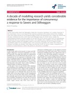
Fig. 11. Three root canal preparation techniques (columns A–C) analysed by micro-CT. Reconstruction of three-
dimensional canal models (rows 1, 3, 4 and cross-sections (row 2) with pre-operative canals in green and postoperative
shapes in red. Reprinted from (327) by permission of the Journal of Endodontics (30: 569, 2004).
Hu¨lsmann et al.
42
efficacy of the device or technique and on its clinical
suitability. Data on working time show large differences
for identical instruments and techniques, which is
because of methodological problems as well as to
individual factors.
Therefore, data from different studies should be
compared with caution, as variation caused by indivi-
duals (169) cannot be defined exactly but should be
regarded as decisive in many cases. For example, it was
demonstrated that instrument fractures resulted in
longer working times for the following instruments in
order to avoid additional fractures (170, 171).
For the evaluation of the efficacy of an instrument the
measurement of the cutting ability therefore seems to
more appropriate (172, 173). Theses studies use an
electric motor driving the root canal instrument into
natural root canals in extracted teeth or artificial canals
in resin blocks, thus excluding individual factors.
However, this does not exactly mirror the clinical
situation either.
In the recent past four major series of standardized
comparative investigations on rotary NiTi instruments
have been published. These will be briefly reviewed.
The Cardiff experimental design
This series of investigations (97–106, 174–177) was
performed in simulated root canals. Four types of root
canals were constructed using size #20 silver points as
templates. The silver points were pre-curved with the
aid of a canal former, to form four different canal types
in terms of angle and location. The four canal types
were:
Curvature 201, beginning of the curvature 8 mm from
the orifice.
Curvature 401, beginning of the curvature 12 mm from
the orifice.
Curvature 201, beginning of the curvature 8 mm from
the orifice.
Curvature 401, beginning of the curvature 12 mm from
the orifice.
The following variables and events were recorded and
evaluated: preparation time, instrument failure (defor-
mation and fracture), canal blockage, loss of working
distance, transportation, canal form (apical stop,
smoothness, taper and flow, aberrations (zips, elbows,
ledges, perforations, danger zones), canal width.
The Zu
¨
rich experimental design
In a series of investigations (50, 138–143) the Zu¨rich
group used high-resolution or micro-CT to measure
changes in canal volume and surface area as well as
differences between pre- and post-preparation root
canal anatomy. The advantages of this non-destructive
technique are three-dimensional replication of the root
canal system, the possibility of repeated measurements
(pre-, intra- and post-operative), and the computer-
aided measurement of differences between two images.
The use of micro-CT enables the evaluation of changes
in volume and surface area of the root canal system, the
extent of unprepared canal surface and canal transpor-
tation in three dimensions (Fig. 11). Similar experi-
ments by other groups have since corroborated and
expanded the findings cited above.
In this system, maxillary molars are embedded into
resin and mounted on SEM stubs, in order to allow
reproducible positioning into the micro-CT. This
approach in conjunction with specific software renders
high reproducibility (139) and allows comparisons of
pre- and post-operative canal shapes with accuracy
approaching the voxel size (currently 18–36 mm).
Specimens are then further characterized with respect
to pre-operative canal anatomy (volume, curvature)
and divided into statistically similar experimental
groups. Analyses can then be carried out with software
that separates virtual root canals, automatically detects
the canal axis and its changes after preparation and the
amount of preparared root canal surface area.
The Go
¨
ttingen experimental design
This series of investigations (13, 91, 92, 137, 170, 171,
178–183) on conventional endodontic handpieces as
well as on several rotary NiTi systems made use of a
modified version of Bramante’s muffle model (125).
A muffle block is used allowing removal and exact
repositioning of the complete specimen or sectioned
parts of it. A modification of a radiographic platform, as
described by Sydney et al. (184) and Southard et al.
(185), may be adjusted to the outsides of the middle
part of the muffle. This allows radiographs to be taken
under standardized conditions, so that these radio-
graphs, taken before, during and after root canal
preparation may be superimposed. A pre-fabricated
stainless-steel crown may be inserted at the bottom of
Mechanical preparation of root canals
43
the middle part of the muffle system to collect apically
extruded debris (Fig. 12A, B).
After embedding, mesio-buccal canals of extracted
mandibular molars with two separate patent mesial
root canals are prepared. Root canal straightening,
working time and working safety are recorded by
superimposition of radiographs taken under standar-
dized conditions. Following this the tooth block is
separated into four parts with a saw, the crown and
three segments with the roots. After taking standar-
dized photographs of the pre-operative cross-section of
the mesio-lingual root canal this is prepared. Again
photographs of the cross-section are taken, allowing
superimposition of both pre- and post-operative canal
circumference and evaluation of changes in cross-
section. Additionally, the percentage of unprepared
root canal wall areas can be measured. Again working
time and procedural incidents are recorded. The three
root segments finally are split longitudinally and the
cleanliness of the root canal walls is evaluated under
SEM using five scores for separate evaluation of
remaining debris (magnification  200) and smear
layer (Â 1000) (65).
While Bramante et al. (125) originally intended
to evaluate changes in cross-sectional diameter, this
model allows the parallel investigation of several
important parameters of root canal preparation:
straightening in the longitudinal axis, changes in root
canal diameter (horizontal), root canal cleanliness,
working time, and safety issues. Initially, an attempt
was made to collect and weigh the apically extruded
debris too, but this part of the model produced
unreliable results. Shortcomings of this model are
related mainly to the irregularities in human root canal
anatomy and morphology.
The Mu
¨
nster experimental design
This recent series of investigations on several rotary
NiTi systems (186–194) uses two types of plastic blocks
with different degrees of curvature (281 and 351) for
the evaluation of straightening and working safety as
well as extracted teeth with severely curved root canals
(25–351) for the evaluation of root canal cleanliness,
working safety and working time.
Manual preparation techniques
Several different instrumentation techniques have been
described in the literature, a summary of some more
popular techniques is presented in Table 3. Some of
these techniques use specially designed instruments
(e.g., the Balanced force technique was described for
Flex-R instruments).
Fig. 12. (a, b) Parts of the muffle system from the Go
¨
ttingen studies (a–c). After removal of the outer parts of the muffle
system a film holder (a) and a holder for reproducible attachment of the X-ray beam (c) can be adjusted to the middle part
of the muffle (b) containing the prepared tooth. Two metal wire are integrated into the film holder, allowing exact
superimposition of the radiograph (arrows).
Hu¨lsmann et al.
44
Manual preparation techniques and
results of studies
Balanced force technique
This technique, reported by Roane & Sabala in 1985
(48, 202), was originally associated with specially
designed stainless-steel or NiTi K-type instruments
(Flex-R-Files) with modified tips in a stepdown
manner. Instruments are introduced into the root
canal with a clockwise motion of maximum 1801 and
apical advancement (placement phase), followed by a
counterclockwise rotation of maximum 1201 with
adequate apical pressure (cutting phase). The final
removal phase is then performed with a clockwise
rotation and withdrawal of the file from the root canal.
Apical preparation is recommended to larger sizes than
with other manual techniques, e.g., to size #80 in
straight canals and #45 in curved canals. The main
advantages of the Balanced force technique are good
apical control of the file tip as the instrument does not
cut over the complete length, good centring of the
instrument because of the non-cutting safety tip, and
no need to pre-curve the instrument (2).
Roane & Sabala (48) themselves and further studies
(49, 50, 131, 185, 203, 207, 208, 213–217) described
good results for the preparation of curved canals
without or with only minimal straightening. However,
others reported a relatively high incidence of procedur-
al problems such as root perforations (218) or
instrument fractures (219). The amount of apically
extruded debris was less than with stepback or
ultrasonic techniques (147, 150, 220), the apical
region showed good cleanliness (221). Varying results
were reported for the amount of dentine removed; in
one study the Balanced force technique performed
superior compared with the stepback technique (126),
while in another study more dentine was removed
1 mm from the apex when using the stepback technique
(222). When used in a double-flared sequence canal
Table 3. Summary of manual root canal preparation techniques described in the literature
Approach Author(s) References
Standardized technique Ingle (1961) (21)
Step-back technique Clem (1969) (195)
Circumferential filing Lim & Stock (1987) (196)
Incremental technique Weine et al. (1970) (197)
Anticurvature filing Abou-Rass et al. (1980) (198)
Step-down technique Marshall & Papin (1980) (199)
Step-down technique Goerig et al. (1982) (200)
Double flare technique Fava (1983) (201)
Crown-down-pressureless technique Morgan & Montgomery (1984) (123)
Balanced force technique Roane et al. (1985) (48, 202)
Canal Master technique Wildey & Senia (1989) (204, 205)
Apical box technique Tronstad (1991) (206)
Progressive enlargement technique Backman et al. (1992) (207)
Modified double flare technique Saunders & Saunders (1992) (208)
Passive stepback technique Torabinejad (1994) (209, 210)
Alternated rotary motions-technique (ARM) Siqueira et al. (2002) (211)
Apical patency technique Buchanan (1989) (212)
Mechanical preparation of root canals
45
area after shaping was larger than after preparation with
Flexogates or Canal Master U-instruments (223).
Post-instrumentation area was also greater in com-
parison with Lightspeed preparation (224), following
ultrasonic preparation or rotary Canal Master prepara-
tion and equal to hand preparation using the stepback
technique (49). A comparison of NiTi K-files used in
Balanced forces motion to current rotary instrument
systems indicated similar shaping abilities (50). How-
ever, some earlier reports had indicated significantly
more displacement of the root canal centres, suggesting
straightening (224, 225).
Cleanliness was rated superior compared with the
crowndown pressureless and stepback techniques (76).
The Balanced force technique required more working
time than preparation with GT Rotary, Lightspeed or
ProFile NiTi instruments (217, 225).
Stepback vs. stepdown
Stepback and stepdown techniques for long have been
the two major approaches to shaping and cleaning
procedures. Serial, telescopic or stepback techniques
commence preparation at the apex with small instru-
ments. Following apical enlargement instrumentation
length may be reduced with increasing instrument size.
Stepdown techniques commence preparation using
larger instrument sizes at the canal orifice, working
down the root canal with progressively smaller instru-
ments. Major goals of crowndown techniques are
reduction of periapically extruded necrotic debris and
minimization of root canal straightening. Since during
the stepdown there is less constraint to the files and
better control of the file tip it has been expected
that apical zipping is less likely to occur. Over the
years several modifications of these techniques have
been proposed, such as the crowndown technique, as
well as hybrid techniques combining an initial step-
down with a subsequent stepback (modified double
flare) (Table 3).
Although stepback and stepdown techniques may be
regarded as the traditional manual preparation techni-
ques there are surprisingly few comparative studies on
these two techniques. There is no definite proof that
‘classical’ stepdown techniques are superior to stepback
techniques. Only the Balanced force technique, which
is a stepdown technique as well, has been shown to
result in less straightening than stepback or standar-
dized techniques (126, 207, 219).
In a comparative study of four preparation techniques
no difference between stepback and crowndown was
detected in terms of straightening, but crowndown
produced more ledges (117). Using the Balanced force
technique, the apical part of curved root canals showed
less residual debris than following preparation with the
crowndown pressureless or stepback technique (76)
although stepback preparation resulted in a larger
increase in canal diameter and more dentine removal
than Balanced force preparation (222).
Crowndown techniques have been reported to
produce less apically extruded debris than stepback
preparation (146, 147, 152, 216).
Conventional rotary systems
In an extensive series of experiments the Go
¨
ttingen
group compared preparation quality, cleaning ability
and working safety of different conventional endodon-
tic handpieces (13). The study involved a total of 15
groups each with 15 prepared teeth. Devices and
techniques evaluated included the Giromatic with two
different files, Endolift, Endocursor, Canal-Leader with
two different files, Canal-Finder with two different files,
Intra-Endo 3-LDSY, manual preparation, Excalibur,
Endoplaner, Ultrasonics and the Rotofile NiTi instru-
ments (in other countries known as MiTy-Roto-Files).
Mean root canal curvature of the different groups in
this study was between 17.81 and 25.11, all root canals
were enlarged to size #35. Further studies were
performed on the Excalibur (226) and the Endoplaner.
Taken together, these studies demonstrated that
preparation of curved root canals using conventional
automated devices with stainless-steel instruments in
many cases resulted in severe straightening. Similar
results earlier already had been found in studies on the
Endolift (13, 52, 54, 63).
Endolift M4 (227, 228).
Endocursor (39, 122, 229).
Excalibur (45, 46, 63, 226, 230–231).
EndoGripper (228).
Intra-Endo 3-LDSY (45, 46, 63, 232).
Endoplaner (63).
Giromatic (39, 52, 54, 70, 122, 233–238).
Canal-Finder System (13, 54, 63, 72, 74, 85, 92,
128, 239–241). In some studies the Canal-Finder
straightened less than or equal to hand instrumenta-
tion (59, 242–244).
Hu¨lsmann et al.
46
Canal-Leader (13, 241, 245, 246).
Ultrasonics (13, 53, 54, 59, 241, 247–254).
Few studies have been published on post-operative
root canal cleanliness after preparation with the devices
mentioned above. The majority of these reported on
large agglomerations of debris and smear layer covering
almost the complete root canal wall (54, 61, 64, 64, 85,
230, 232, 255). In some studies slightly superior
results were found for automated systems with
integrated water supply, for example the Canal Finder
and the Canal Leader (65, 75, 256).
Additionally, for some of the automated devices severe
problems concerning safety issues (apical blockages, loss
of working length, perforations and instrument frac-
tures) have been reported (13, 54, 58, 59, 63, 94, 110,
111, 152, 226, 227, 230, 237, 243, 257–263).
NiTi systems
Metallurgical aspects
Several metallurgical aspects of NiTi instruments have
been extensively reviewed previously (264–266). Two
of the main characteristics of this alloy, composed of
approximately 55% (wt) nickel and 45% (wt) titanium
are memory shape and superior elasticity. The elastic
limit in bending and torsion is two to three times higher
than that of steel instruments. The modulus of elasticity
is significantly lower for NiTi alloys than for steel,
therefore much lower forces are exerted on radicular
wall dentine, compared with steel instruments. These
unique properties are related to the fact that NiTi is a
so-called ‘shape memory alloy’, existing in two
different crystalline forms: austenite and martensite.
The austenitic phase transforms into the martensitic
phase on stressing at a constant temperature and in this
form needs only light force for bending. After release of
stresses the metal returns into the austenitic phase and
the file regains its original shape. Because of the metallic
properties of NiTi, it became possible to engineer
instruments with greater tapers than 2%, which is the
norm for steel instruments (266).
Instrument designs
Over the years several different NiTi systems have been
designed and introduced on the market (see Table 1).
This review does not aim at a detailed presentation,
description and analysis of specific instrument designs,
but it should be kept in mind that design features such
as cutting angle, number of blades, tip design, conicity
and cross-section, will influence the instruments’
flexibility, cutting efficacy, and torsional resistance.
Design and clinical usage of some of these NiTi systems
are described in detail elsewhere in this issue.
Motor systems
Initially, NiTi instruments were used in regular low-
speed dental handpieces, which resulted in a clinically
unacceptable number of instrument fractures. In
consequence, special motors with constant speed and
constant torque were introduced for use with these
instruments (Table 4). Earlier concepts preferring
high-torque motors were followed by development of
low-torque motors, some of which have several special
features as auto start/stop, auto apical reverse in
combination with an electronic device for determina-
tion of working length, auto torque stop, auto torque
reverse, handpiece calibration, twisting motion and
programmed file sequences for primary preparation
and retreatment.
Initially, high-torque motors were preferred in order
to allow efficient cutting of dentine and to prevent
locking of the instrument. However, the incidence of
instrument fractures was relatively high with these
motors. The rationale for the use of low-torque or
controlled-torque motors with individually adjusted
torque limits for each individual file is to keep the
instrument working below the limit of instrument
elasticity without exceeding the instrument-specific
torque limit thus reducing the risk of instrument
fracture (267). The values should range between the
martensitic start clinical stress and the martensitic finish
clinical stress, which is dependent on design and taper
of the individual instrument.
On the other hand, current norms stipulate the
measurement of torque at failure at D3, a distance of
3 mm from the tip of the instrument. For an instrument
with a taper of 0.06 and larger, it becomes difficult to
determine a torque that is sufficient to rotate the larger
more coronal part of the instrument efficiently while
not endangering the more fragile apical part. In fact, it
has been suggested repeatedly that the creation of a
glide path allows the apical end of the instrument to act
as a passive pilot and thus protects the instrument from
breakage even with high torque.
Mechanical preparation of root canals
47
Table 4. Endodontic motors for root canal preparation using Ni–Ti instruments
Motor Company Torque values NiTi systems
Nouvag TCM 3000 Nouvag, Goldbach, Switzerland High torque 5 values: 10/20/35/45/55 Ncm All systems
Nouvag TCM Endo Nouvag Low torque 1.0 N cm, -(no limit)- All systems
Nouvag TCM Endo V
n
Nouvag Low torque 10 values: 0.2–5.0 N cm All systems
EndoStepper Komet, Lemgo, Germany Right torque Individual for any file All systems
IT control VDW Right torque Individual for any file All systems
E-master VDW Right torque Individual for any file; 10 values: 0.2–3.0 N cm Only FlexMaster
ATR Tecnika Dentsply, La Pistoia, Italy, Low torque Individual for any file All systems
K3-etcm Kerr, Karlsruhe, Germany Low torque 5 values: o0.5, o0.9, 1.2, 1.7, 2.0 Ncm K3
Surgimotor III Aseptico, Woodville, NJ, USA 5 values All systems
Quantec ETM Sybron Endo Quantec, K3
TriAuto ZX
n
Morita, Tokio, Japan Low torque 7 values All systems
Dentaport
n
Morita, Tokio, Japan Low torque 11 values All systems
ENDOflash KaVo Low torque 3 values: 0.05, 0.09, 0.14 N cm All systems
ENDOadvance KaVo Low torque 4 values: 0.25, 0.5, 1.0, 3.0 N cm All systems
Anthogyr-handpiece Dentsply, Ballaigues, Switzerland Low torque 4 values: o1, 1, 2.25, o4.5 Ncm All systems
Endy 5000
n
Ionyx, Blanquefort, France Low torque All systems
Endo-Mate TC NSK Europe, Frankfurt, Germany, Low torque 6 values: 0.7, 1.5, 2.3, 3.0, 3.7, 4.5 Ncm All systems
Tascal-handpiece Max-Dental, Augsburg, Germany Undefined Handpiece for prophylaxis Lightspeed
SiroNiti- handpiece Sirona, Breitenbach, Germany Low torque 5 values All systems
Please note, that some of these motors are distributed in some countries under different names and by different distributors.
n
Combined with electrical root canal length measurement device.
Due to higher rotational speed not all motors are suited for use with Lightspeed.
Hu¨lsmann et al.
48
Table 5. Brief summary of investigations comparing various NiTi instruments regarding their shaping ablitity
Author(s) References Year NiTi system Method Result
Esposito & Cunningham (273) 1995 Mac-Files, hand & rotary Extracted teeth NiTi superior to K-Flex manual
Glosson et al. (274) 1995 Lightspeed, Mity manual Extracted teeth LS superior to Mity man. and K-Flex manual
Knowles et al. (275) 1996 Lightspeed Extracted teeth Little or no transportation
Gambill et al. (134) 1996 Mity-files Extracted teeth Superior to K-Flex manual
Coleman et al. (276) 1996 Ni–Ti–K-files vs.steel files Extracted teeth Ni–Ti superior with minimal straightening
Zmener & Banegas (277) 1996 ProFile 0.04 Resin blocks Superior to ultrasonics and K-files
Chan & Cheung (278) 1996 Mity-files Resin blocks Superior to K-files
Tharuni et al. (279) 1996 Lightspeed Resin blocks Superior to K-files
Short et al. (225) 1997 ProFile 0.04, Lightspeed, McXim Extracted teeth All superior to Flex-R
Thompson & Dummer (103, 104) 1997 Lightspeed Resin blocks Minimal transportation
Thompson & Dummer (280, 281) 1997 NT Engine, McXim Resin blocks Minimal transportation
Thompson & Dummer (99, 100) 1997 ProFile 0.04, series 29 Resin blocks Little transportation
Bryant et al. (97, 98) 1998 ProFile 0.04 with ISO tips Resin blocks Little straightening, some zips
Coleman & Svec (282) 1997 NiTi-K-Files vs. steel files Resin blocks NiTi sig. less straightening, better centering
Thompson & Dummer (174) 1998 Mity Roto, Naviflex Resin blocks No difference, little straightening, many ledges
Thompson & Dummer (105, 106) 1998 Quantec Series 2000 Resin blocks More aberrations by larger instruments
Kavanagh & Lumley (283) 1998 ProFile 0.04 & 0.06 Extracted teeth No difference, little or no transportation
Shadid et al. (224) 1998 Lightspeed Extracted teeth Superior to Flex-R
Scha
¨
fer & Fritzenschaft (194) 1999 HERO 642 Resin blocks HERO 642 superior to ProFile 0.04 superior to K-Flexofiles
ProFile 0.04
Bryant et al. (175) 1999 Combination of
ProFile 0.04 and 0.06
Resin blocks Adequate shape with little straightening
Ottosen et al. (284) 1999 ProFile 0.04 vs. Naviflex Extracted teeth Little transportation, no difference
Mechanical preparation of root canals
49
Table 5. Continued
Author(s) References Year NiTi system Method Result
Kum et al. (285) 2000 ProFile 0.0 & GT Rot. vs. steel files Resin blocks Ni–Ti superior to K-Flexofiles
Jardine & Gulabivala (286) 2000 McXIM Extracted teeth Equal to Flexofiles manual
ProFile 0.04 Extracted teeth Equal to Flexofiles manual
Thompson & Dummer (101-102) 2000 HERO 642 Resin blocks Few aberrations
Griffiths et al. (176) 2000 Quantec LX Resin blocks Outer widening in 55–80%
Griffiths et al. (177) 2001 Quantec SC Resin blocks Severe aberrations after instr. no.7, outer widening
Gluskin et al. (287) 2001 GT Rotary vs. Flexofiles Extracted teeth Little transportation, superior to Flexofiles
Bertrand et al. (288) 2001 HERO 642 Extracted teeth Little transportation, superior to steel hand files
Peters et al. (140) 2001 Lightspeed, ProFile 0.04, GT Rotary Extracted teeth Little transportation
Hu¨lsmann et al. (178) 2001 HERO 642 vs. Quantec SC Extracted teeth No difference, little or no transportation
Calberson et al. (289) 2002 GT Rotary Resin blocks Little transportation
Bergmans et al. (290) 2002 Lightspeed vs. GT Rotary Extracted teeth No difference, little transportaion
Scha
¨
fer & Lohmann (187) 2002 FlexMaster vs. K-Flexofile Resin blocks Minimal transportation, superior to K-Flexofiles
Scha
¨fer
& Lohmann (188) 2002 FlexMaster vs. K-Flexofile Extracted teeth FlexMaster superior to K-Flexofiles
Versu¨mer et al. (179) 2002 ProFile 0.04 vs. Lightspeed Extracted teeth No difference, little or no transportation
Hu¨lsmann et al. (180) 2003 FlexMaster vs. HERO 642 Extracted teeth No difference, little or no transportation
Weiger et al. (291) 2003 FlexMaster vs. Lightspeed Extracted teeth Little transportation, Lightspeed superior to FM
Hu¨bscher et al. (143) 2003 FlexMaster Extracted teeth Little transportation
Scha
¨
fer & Florek (189) 2003 K 3 Resin blocks Little transportation, superior to K-Flexofiles
Scha
¨
fer & Schlingemann (190) 2003 K 3 Extracted teeth Little transportation, superior to K-Flexofiles
Peters et al. (292) 2003 ProTaper Extracted teeth Little transportation
Bergmans et al. (293) 2003 ProTaper vs. K3 Extracted teeth Little transportation
Hu¨lsmann et al.
50
However, in a comparative study of a low-torque
(o1 N/cm) and a high-torque (43 N/cm) motor
with used rotary NiTi instruments the former yielded
significantly higher resistance to cyclic fatigue com-
pared with usage at high torque (268).
It should be noted in this context that systematic
comparative studies of different endodontic motors are
missing. This is also at least in part because of current
norms that do not mirror the clinical situation for
rotary instruments and the scarcity of adequately
controlled experiments.
Studies on root canal preparation using NiTi
systems
Cleaning ability
Studies on various NiTi instruments (Table 5) in the
last years have focused on centring ability, maintenance
of root canal curvature, or working safety of these new
rotary systems; only relatively little information is
available on their cleaning ability. It should be
mentioned that the term ‘canal cleaning’ is used in this
review for the ability to remove particulate debris from
root canal walls with cleaning and shaping procedures.
This property usually has been determined using
scanning electron micrographs (for a review see (13)).
For example, the results for Quantec instruments
were clearly superior to hand instrumentation in the
middle and apical third of the root canals with the best
results for the coronal third of the root canal. In many
specimens only a thin smear layer could be detected
with many open dentinal tubules (81). Kochis et al.
(269) could find no difference between Quantec and
manual preparation using K-files. Peters et al. (270) and
Bechelli et al. (271) described a homogeneous smear
layer after Lightspeed preparation. In a further study no
differences between Quantec SC and Lightspeed could
be found (181), both systems showed nearly complete
removal of debris but left smear layer in all specimens.
In the majority of specimens in both groups cleanliness
was clearly better in the coronal than in the apical part
of the root canals. The results are comparable with
those in previous studies (178–180). However, in the
latter studies EDTA was used only as a paste during
preparation but a final irrigation with a liquid EDTA
solution may increase the degree of cleanliness. In
contrast, FlexMaster, ProTaper and HERO 642
showed nearly complete removal of debris, leaving
Table 5. Continued
Author(s) References Year NiTi system Method Result
Hu¨lsmann et al. (181) 2003 Lightspeed vs. Quantec SC Extracted teeth No difference, little or no transportation
Braun et al. (294) 2003 ProFile, FlexMaster. K-Files Extracted teeth ProFile & FlexMaster superior to K-files
Veltri et al. (295) 2004 GT Rotary vs. ProTaper Extracted teeth No difference, little or no transportation
Scha
¨fer
& Vlassis (191) 2004 ProTaper vs. RaCe Extracted teeth RaCe sign. better than ProTaper
Scha
¨fer
& Vlassis (192) 2004 ProTaper vs. RaCe Resin blocks RaCe superior to ProTaper
Paque et al. (170) ProTaper vs. RaCe Extracted teeth No difference, little or no transportation
Mechanical preparation of root canals
51
only a thin smear layer with a relatively high percentage
of specimens without smear layer (170, 180). Prati et al.
(272) found no difference between stainless-steel K-
files and K3, HERO 642, and RaCe NiTi instruments.
Following preparation with FlexMaster and K3,
Scha
¨
fer & Lohmann (188) and Scha
¨
fer & Schlinge-
mann (190) found significantly more debris and smear
layer than after manual preparation with K-Flexofiles,
although these differences were not significant for the
middle and apical thirds of the root canals. RaCe
performed better when compared with ProTaper
(192). They discovered uninstrumented areas with
remaining debris in all areas of the canals irrespective of
the preparation technique with the worst results for the
apical third. This is in agreement with the results of
several earlier studies on post-preparation cleanliness
(63, 178–181, 193, 272). These findings underline the
limited efficiency of endodontic instruments in clean-
ing the apical part of the root canal and the importance
of additional irrigation as crucial for sufficient desinfec-
tion of the canal system. Compared with results of a
similar study using ProFile NiTi files, Scha
¨
fer &
Lohmann (188) found FlexMaster to be superior to
K-Flexofiles in terms of debris removal and concluded
that different rotary NiTi systems vary in their debris
removal efficiency, which is possibly because of differ-
ing flute designs. The comparison of previous studies
on instruments with and without radial lands (ProFile,
Lightspeed, HERO 642) (178–181) confirms the
finding that radial lands tend to burnish the cut dentine
onto the root canal wall, whereas instruments with
positive cutting angles seem to cut and remove the
dentine chips.
Nevertheless, it must be concluded from the pub-
lished studies that the majority of NiTi systems seems
unable to completely instrument and clean the root
canal walls.
Straightening
Results of selected studies on shaping effects of rotary
NiTi systems are presented in Table 5. The vast
majority of these studies uniformly describe good or
excellent maintenance of curvature even in severely
curved root canals. This is confirmed by several
investigations of post-operative cross-sections showing
good centring ability with only minor deviations from
the main axis of the root canal (134, 224, 226, 228,
274, 278, 284, 296–300).
It has been further demonstrated that adequate
preparation results can be obtained with NiTi instru-
ments, even by untrained operators and inexperienced
dental students (287, 301–303).
Safety aspects
Major concern has been expressed concerning the
incidence of instrument fractures during root canal
preparation (194). Two modes of fractures can be
distinguished: torsional and flexural fractures (304,
305). Flexural fractures may arise from defects in the
instrument surface and occur after cyclic fatigue (306).
The discerning feature is believed to be the macro-
scopic appearance of fractured instruments: those with
plastic deformation have fractured because of high
torsional load while fragments with no obvious signs
are thought to have fractured because of fatigue (304).
A summary of factors that may influence instrument
separation is presented in Table 6. Anatomical condi-
tions such as radius and angle of root canal curvature,
the frequency of use, torque setting and operator
experience are among the main factors, while selection
of a particular NiTi system, sterilization and rotational
speed, when confined to specific limits, seem to be less
important (307–338).
Further aspects of working safety such as frequency of
apical blockages, perforations, loss of working length
or apical extrusion of debris until now have not been
evaluated systematically. From the studies described so
far it may be concluded that loss of working length and
apical blockages in fact do occur in some cases, while
the incidence of perforations seems to be negligible.
The amount of apically extruded debris has been
evaluated in three studies and reported to be not
significantly different to hand preparation with Ba-
lanced force motion or conventional rotary systems
using steel files (13, 153, 154).
Working time
The majority of comparative studies presents some
evidence for shorter working times for rotary NiTi
preparation when compared with manual instrumenta-
tion. NiTi systems using only a small number of
instruments, for example ProTaper, completed pre-
paration clearly faster than systems using a large
number of instruments (e.g., Lightspeed). It should
be noted that reported working times for hand
Hu¨lsmann et al.
52
Table 6. Summary of references investigating the influence of various factors on deformation and separation of NiTi instruments
Author(s) Year References Analyzed factor Ni–Ti system Method Influence
Silvaggio &
Hicks
1997 (307) Sterilization ProFile 0.04 1–10 cycles Torsional test No
Pruett et al. 1997 (308) Canal curvature & rot.
speed
Lightspeed 30–601 curvatures, Simulated canals Yes
2–5 mm radius and 750,
1300, 2000 r.p.m.
Yes
No
Haikel et al. 1998 (309) NaOCl as irrigant Different systems Preparation with/
without NaOCl
Torsional test No
Mize et al. 1998 (310) Sterilization Lightspeed No
Mandel et al. 1999 (311) Operator experience ProFile 0.04 and 0.06 5 operators Simulated canals Yes Better results in
second turn
Baumann &
Roth
1999 304 Operator experience ProFile 0.04 Students vs.
practitioners
Simulated canals No
Gabel et al. 1999 (312) Rotational speed ProFile 0.04 166 vs. 333 r.p.m. Extracted teeth Yes 166 r.p.m. with less
fractures/distortions
Haikel et al. 1999 (313) Radius of curvature in-
strument taper & size
ProFile 0.04 and 0.06,
HERO 642, Quantec
5 and 10 mm radius Fatigue test Yes Earlier fracture with low
radius
Yes Earlier fracture with incr.
size
Yared et al. 1999 (314) Sterilization &
simulated clinical use
ProFile 0.06 5 vs. 10 canals/
sterilization cycles
Extracted teeth No
Dietz et al. 2000 (315) Rotational speed ProFile 0.04 150/250/350 r.p.m. Yes Less fractures with
150 r.p.m.
Yared et al. 2000 (316) Sterilization & clinical
use
ProFile 0.06 No
Hilt et al. 2000 (317) Sterilization NiTi files 10–40 cycles, 2 autoclaves No
Mechanical preparation of root canals
53
Table 6. Continued
Author(s) Year References Analyzed factor Ni–Ti system Method Influence
Bortnick et al. 2001 (318) Motor ProFile 0.04 electric vs. airdriven
handpiece
Extracted teeth No
Daugherty
et al.
2001 (319) Rotational speed ProFile 0.04 150 vs. 350 r.p.m. Extracted teeth No
Gambarini 2001 (320) Motor ProFile 0.04 and 0.06 high- vs. low-torque Used instruments Yes Low-torque favorable
Gambarini 2001 (321) Frequency of use ProFile 0.04 and 0.06 new/used (10 Â )
instruments
Yes Earlier fract. for used
instr.I58
Tygesen et al. 2001 (322) NiTi system ProFile 0.04 Extracted teeth No
Ni–Ti Pow-R 0.04
Yared et al. 2001a (323) Rotational speed ProFile 0.06 150/250/350 r.p.m. Extracted teeth Yes 150r.p.m. superior to
350 r.p.m.
operator
experience
3 operators with
different experience
Yes
torque 20/30/55 Ncm No
Yared et al. 2001b (324) Motor ProFile 0.06 high- vs. low-torque Extracted teeth No
Yared et al. 2002 (325) Rotational speed GT Rotary 150/250/350 r.p.m. Extracted teeth No
Torque operator
experience
20/30/55 Ncm 3
operators with
different experience
No
No
Li et al. 2002 (326) Rotational speed,
handling mode angle
of curvature
ProFile 0.04 200/300/400 r.p.m. Fatigue test Yes
Yes
Peters &
Barbakow
2002 (305) Number of rotations,
torque, force, handling
parameters simulated
canals vs. teeth
ProFile 0.04 ProFile 0.04/15,
0.04/30, 0.04/45
Fatigue test Yes Sign. more rot. to fract.
For 0.04/15
Hu¨lsmann et al.
54