Pseudo Velocity Shock Spectrum Rules For Analysis Of Mechanical Shock pdf
Bạn đang xem bản rút gọn của tài liệu. Xem và tải ngay bản đầy đủ của tài liệu tại đây (3.84 MB, 36 trang )
Pseudo Velocity Shock Spectrum Rules For Analysis Of Mechanical
Shock
Howard A. Gaberson, P.E., Ph.D.
234 Corsicana Drive
Oxnard, CA 93036
ABSTRACT: I have taken on the job of recording the features and use of the pseudo
velocity shock spectrum (PVSS) plotted on four coordinate paper (4CP). Some of the
newer rules could be presented as a separate paper, but knowledge of the PVSS on 4CP is
so limited that few would understand the application. An integrated document is needed
to show how all the concepts fit together. The rules cover the definition, interpretation
and accuracy of four coordinate paper, simple shock spectrum shape, drop height and the
2g line, pseudo velocity relation to modal stress, shock severity, destructive frequency
range, shock isolation, use with multi degree of freedom systems, low frequency
limitation of shaker shock, and relation to the aerospace acceleration SRS concept. I
hope that' by showing you the wide applicability of PVSS on 4CP analysis, that I can
convince you to use it.
Introduction: Dick Chalmers (Navy Electronics Lab, San Diego, CA) and Howie
Gaberson (Navy Facilities Lab in Port Hueneme, CA) worked on shock during the late
sixties to define equipment fragility and its measurement. Chalmers’ Navy experience in
organizing severe ship shocks by induced velocity led us to an independent discovery that
induced modal velocity, not acceleration, was proportional to stress. We published that in
1969. Earlier others had discovered and written on the same subject. No one paid any
attention. At Chalmers’ insistence, in the early 90’s, we started pushing the concept
again, and we connected it to the pseudo velocity shock spectrum plotted on four
coordinate paper (PVSS on 4CP), a 1950’s concept. Matlab came along and made the
PVSS calculation and 4CP plotting easy. It turns out that PVSS indicates multi degree of
freedom system modal velocity through a participation factor. Dick died in 1998 but his
results are certainly in this paper. PVSS on 4CP was used at least in the late 50’s, and
Eubanks and Juskie [23] employed it for installed equipment fragility in their 50-page
1963 Shock and Vibe Paper. Civil, nuclear defense, and Army Conventional Weapons
defense, have adopted the convention. Howie has recently been assembling the rules and
reasons that explain the use of PVSS on 4CP for measuring the destructive potential of
violent shock motions. This paper attempts to assemble them in one convenient
document.
Shock Spectrum Definitions: The shock spectrum is a plot of an analysis of a motion
(transient motions due to explosions, earthquakes, package drops, railroad car bumping,
vehicle collisions, etc.) that calculates the maximum response of many different
frequency damped single degree of freedom systems (SDOFs) exposed to the motion.
The response can be: positive, negative, or maximum of the two. It can be calculated for
during, or residual (after), the shock motion, overall or maximum of the maximum is
most common. The SDOFs can be damped or undamped. It can be plotted in terms of
relative or absolute: acceleration, velocity, or displacement. The most important plot is on
four coordinate paper, (4CP) in terms of pseudo velocity.
PVSS4CP (PSEUDO VELOCITY SHOCK SPECTRUM PLOTTED ON FOUR
COORDINATE PAPER) IS A SPECIFIC PRESENTATION OF THE RELATIVE
DISPLACEMENT SHOCK SPECTRUM THAT IS EXTREMELY HELPFUL FOR
UNDERSTANDING SHOCK. PSEUDO VELOCITY EXACTLY MEANS PEAK
RELATIVE DISPLACEMENT, Z, MULTIPLIED BY THE NATURAL FREQUENCY
IN RADIANS,
()
k
m
.
Many papers were published wasting time calculating eloquent acceleration shock spectra
(called SRS) of the classical pulses, (i.e., half sine, haversine, trapezoid, saw tooth).
Examples of these articles are [1, 2, 3, 4]. I think these are unimportant. The acronym
SRS has come to mean a log log plot of the absolute acceleration shock spectrum and is
used extensively by the aerospace community. The structural community and the Navy
use the PVSS 4CP.
Shock Spectrum Equation: Fig. 1 is the SDOFs model to explain the shock spectrum
where:
y is the shock motion applied to the bogey or heavy wheeled foundation.
x is the absolute displacement of the SDOF mass
z is the relative displacement, x - y.
.
m
x
y
k
c
h
Figure 1. The shock table wheeled bogey with a
single degree of freedom system (SDOFs) attached.
The free body diagram of the mass is in Fig. 2.
c(x y)−
&&
k(x y)
−
x
&&
m
Figure 2. The free body diagram of the mass with forces.
Applying F = ma on the FBD of Fig. 2 gives us Eq. (1).
(1)
()()cx y kx y mx
−−− −=
&& &&
,
Using relative coordinates, defined as: z = x - y, gives (Eq. (2)):
(2)
(),cz kz m z y or
mz cz kz my
−− = +
++=−
&&
&&&
&&
&& &
Dividing by “m,” and substituting the definitions and symbols of Eq. (3a) give Eq. (3).
n
k
m
ω=
,
c
c
c
ζ= , and
2
c
k=c (3a) m
y
−
(3)
2
2
n
n
zzzζω ω
++=
&&
&& &
Equation (3) is the shock spectrum equation, and the shock spectrum is our tool for
understanding shock. In Eq. (3), is the shock. O’Hara [5] gives the solution explicitly
with initial conditions as follows (Eq. (4)):
y
&&
( )
()
0
0
0
1
cos sin sin ( ) sin ( )
t
t
t t
dd d
d
dd
ze
zze t t t ye t d
ζω
ζω ζω τ
ζ
ωω ω τ ωτ
ηωω
−
− −−
=++−
∫
&
&&
τ
−
(4)
Where: initial values of
z
=
00
z,z
&
z,
&
damped natural frequency,
=ω
d
η
ω
2
1 ζ−=η
integration time variable
=τ
Shock Spectrum Calculation
Equation (4) is applied from point to point giving a list of z’s. The maximum value of z
multiplied by the frequency in radians is the pseudo velocity,
ω , for that frequency. If
you think of applying that equation to the whole shock, (as though you knew how to
write an equation for the shock) from time equals zero, to after the shock is over, the
initial terms will be zero and we have z and a function of time given by Eq. (5).
max
z
()
0
1
() sin ( )
t
t
d
d
zye t
ζω τ
τω
ω
−−
=− −
∫
&&
d
ττ
(5)
The PVSS, is the maximum value of this for each frequency multiplied by
ω
()
max
0
max
1
() sin ( )
t
t
d
d
PV z y e t d
ζω τ
ωω τ ωττ
ω
−−
==− −
∫
&&
y
(5a)
The undamped equations are Eqs (6), (6a), and (6b).
(6)
2
n
zzω+=−
&&
&&
0
1
()sin ( )
t
zy t
τωτ
ω
=− −
∫
&&
d
τ
τ
(6a)
(6b)
max
0
max
()sin ( )
t
PV z y t dωτωτ
==− −
∫
&&
I had to lead you to Eq. (6b), because I want you to believe it. We’re coming back to Eq.
(6b) when we do multi degree of freedom systems (MDOFS), and shock isolation.
ZERO MEAN SIMPLE SHOCK: The shock in Figures 3, is a zero mean simple
shock. Zero mean acceleration means shock begins and ends with zero velocity. This
means the motion analyzed includes the drop, as in the case of a drop table shock
machine shock. The integral of the acceleration is zero if it has a zero mean. By simple
shock I mean one of the common pulses: half sine, initial peak saw tooth, terminal peak
saw tooth, trapezoidal, haversine
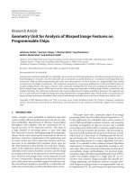
PVSS-4CP Example, 1 ms, 800 g Half Since: As an example Fig. 3 shows a drop table
shock machine 800 g, 1 ms, half sine shock motion and its integrals; this is the motion, y,
in Fig. 1. (I saw this 800 g, 1 ms, half sine listed for non operational shock capability on
the package of a 60 gig Hammer USB Hard Drive.) Fig. 4 shows its PVSS on 4CP for 5%
damping.
Figure 3. Time history of acceleration, velocity, and displacement
of a drop table shock machine half sine shock.
Figure 4. PVSS on 4CP for the half sine shock of Figure 3. Notice the high frequency
asymptote is on the constant 800 g line, that the velocity plateau is at a little under
196 ips, and that the low frequency asymptote is on a constant displacement
line of about 50 inches
Figure 4, our PVSS on 4CP, for that hard drive non operational shock, shows a lot of
information. We’ll talk more about this later, but for now you see a peak 800 g constant
acceleration line sloping down and to the right for the high frequencies, you see a mid
frequency range plateau at just under the velocity change that took place during the
impact, (196 ips) and you see a low frequency constant displacement asymptote at the
constant maximum displacement of the shock, the 50-inch drop, sloping down and to the
left.
Four Coordinate Paper, 4CP is Sine Wave Paper. Every Point Represents a Specific
Sine Wave With a Frequency and a Peak Displacement, Velocity, and Acceleration:
To explain this 4CP, think of a sine wave vibration, which has a frequency and a peak
deflection, a peak velocity, and a peak acceleration. The four are related; knowing any
two, the others pop out. Frequency is in Hz. The deflection is in inches, the velocity is in
inches per second, ips, and the acceleration is in g’s. Four coordinate paper (4CP) is a log
log vibration sine wave nomogram displaying the sine wave relationship with four sets of
lines, log spaced: vertical for frequency, horizontal for velocity, down and to the right for
acceleration, and down and to the left for deflection.
Zero Mean Simple Shock General Shape
WHEN A ZERO MEAN SHOCK PVSS IS PLOTTED ON 4CP IT HAS A HILL
SHAPE: THE LEFT UPWARD SLOPE IS A PEAK DISPLACEMENT ASYMPTOTE.
THE RIGHT DOWNWARD SLOPE IS THE PEAK ACCELERATION ASYMPTOTE.
THE TOP IS A PLATEAU AT THE VELOCITY CHANGE DURING IMPACT.
THE LOGIC FOR PLOTTING PVSS ON 4CP
When we use four coordinate paper for plotting pseudo velocity shock spectra, every
point on the plot represents four values. For that frequency the relative displacement, z,
and pseudo velocity, ωz, are exact. (Displacement is exactly calculated, and PV is just
ωz.) The indicated acceleration (which has to ω
2
z
max
) is the absolute acceleration at the
instant of maximum relative displacement, regardless of the damping. This can be
explained as follows. The shock spectrum calculating equation is
(3)
2
2
zzzζω ω++=
&&
&& &
y−
x
From our definition of the relative coordinate, z, we have
(3b)
,,z x y and z x y
thus
yzx
=− =−
−=−
&& &&
&&
&& &&
&&
Substituting (3b) into (3a) we have
(3c)
2
2
zzζω ω+=−
&&
&
When the damping is zero, we have Eq (3d), and this is the indicated acceleration on the
4CP. For the undamped case, the indicated acceleration is exact.
(3d)
2
max
=−
&&
zω x
When the damping is not zero, consider the following. The shock spectrum calculates the
maximum value of z. At an instant of maximum z, its derivative, , has to be zero.
Thus at any instant of maximum z, Eq (3d) still holds. Thus the indicated acceleration on
the 4CP for damped spectra, it is indeed the exact absolute acceleration of the mass at the
instant that z is equal to z
z
&
max
. But this is not necessarily that maximum acceleration of
the mass at that frequency. So the acceleration values on the damped PVSS are only
approximate for max acceleration of the mass. It's probably close if damping is small and
because the acceleration asymptote is exact at high frequencies.
Similarly and importantly, if you compute an acceleration shock spectrum, the SRS, the
pseudo velocity you would get from dividing by
ω
, that is
max
x
ω
&&
is not the same as the
pseudo velocity
ω
; they don't occur at the same instant. This is a problem and maybe
the only way it can be evaluated is to calculate some example cases.
max
z
Understanding the PVSS Plateau When PVSS is Plotted On 4CP: All PVSS have a
plateau; and it is the region where the shock is most severe so you have to understand it.
Sometimes it’s very short and sometimes long. Collision shocks don't begin and end with
zero velocity, and are almost all plateau.
To explain why the plateau occurs, think with me in the following way. Think of an
instantaneous shock. Go back and look at Figure 1. The bogey, is way heavier than the
mass, like the table on a drop table shock machine. It is released and falls from a height,
h, and hits a shock programmer (pad or whatever) that brings it to rest or zero velocity
with one of the traditional simple shock impacts (i.e., half sine, sawtooth, trapezoid,
haversine) that has a peak acceleration,
. Both the bogey and the mass fall
substantially together and attain a peak velocity of
max
y
&&
2
i
y
=−
&
o
x
&
gh. Just after the impact, the
bogey velocity, , suddenly becomes zero, but , the mass velocity, hasn't yet changed.
Since , and,
has just become zero, , and we have the initial velocity
case for that undamped homogeneous solution, Eq. (4a), with
y
&
y
&
x
&
0
z
&
zx
=−
&
&
y
&
=
0
2z=
&
gh
, and
.
We take Eq (3), with no damping, and no shock acceleration, which gives us Eq (4a).
0
0z =
0
0
z
zzcost sin=ω+
ω
&
tω
(4b)
Again: the bogey and the mass fall together, and the shock is over before the spring does
any compressing. The bogey suddenly comes to rest and then the mass starts vibrating.
This is undamped initial value free vibration of Eq (4b). Just before impact, the mass and
the bogy have the same velocity, or
2
==−
&&
xy gh (4c)
After impact,
, but still,
0
0, 0
=
&
zy
=
2
=−
&
xgh y
0
x
. Since
,
, in the
initial velocity case, with
zx
=−
&&
&
0
=
&
&
z
0
&
2
o
zx g
==
&
h. so
0
2
sin sin
gh
z
ztω
ωω
−
==
&
tω
, (4d)
and max pseudo velocity is.
2zgω= h (4e)
Now, as simple as that is, that’s how/why we get a plateau. All SDOF, with half periods
much longer than the impact duration, end up vibrating with the same peak velocity, the
impact velocity, no matter what their natural frequency. In this undamped sinusoidal
motion, the relative velocity and the pseudo velocity have the same maximum values;
they both all continue to vibrate forever with this peak velocity, the impact velocity. The
maximum pseudo velocity is the impact velocity, so all SDOFS with periods much longer
than the shock, will have the same maximum pseudo velocity. This is why we see the
plateau; the shock spectrum of a simple shock will have a constant PV plateau for quite a
wide frequency interval.
UNDAMPED PVSS'S OF SIMPLE DROP TABLE SHOCKS HAVE A FLAT
CONSTANT PSEUDO VELOCITY PLATEAU AT THE VELOCITY CHANGE THAT
TOOK PLACE DURING THE SHOCK.
The High Frequency Asymptote is the Constant Acceleration Line at the Peak
Acceleration: There are limits to the frequencies at which this plateau can continue. In
the very high frequency region, think of the mass as very light and the spring very stiff;
so stiff that the mass exactly follows the input motion. The acceleration of the mass is
equal to the acceleration of the foundation. In this region the maximum relative
deflection, z, is given by the maximum force in the spring over its stiffness, k. The
maximum force is the ma force,
mx , and . Thus the maximum spring stretch is:
&&
max max
xy
=
&& &&
max max
max max max
2
1
.
n
Fmx
m
zy
kkk
ω
== = =
&&
&& &&
y
(10)
So for the high frequency region the pseudo velocity:
max
max
n
y
PV zω
ω
==
&&
(10a)
The very high frequency pseudo velocity asymptote is the peak acceleration divided by
the natural frequency, and this is the 4CP constant acceleration line at the peak
acceleration. I have calculated and plotted all of the simple shocks [6]. I’ve found that on
the RHS of the PVSS on 4CP, near the intersection of the acceleration asymptote and the
plateau, the PVSS starts sloping downward at a higher acceleration than the asymptote
but does not exceed twice a
max
.
THE HIGH FREQUENCY LIMIT OF THE PLATEAU OF THE UNDAMPED PVSS
OF THE SIMPLE SHOCKS OF THE HIGH PV REGION IS SET BY THE MAXIMUM
ACCELERATION OF THE SHOCK.
The Low Frequency Asymptote of a Zero Mean Shock is a Constant Displacement
Line at the Peak Displacement: Now on the low frequency end of the plateau, imagine
the following: the mass is heavy and the spring is extremely soft, so the mass won't even
start to move until the bogey has fallen, come to rest, and the impact is over. Then it
notices it has deflected an amount “h,” and it starts vibrating with amplitude “h” forever.
The deflection cannot exceed the drop height. Thus, on the left side of the PVSS on 4CP,
z = h and the PV will be:
zhωω=
And that’s a line sloping down and to the left at a constant deflection, “h.”
Notice: The Low Frequency Limit of the Plateau of the PVSS on 4CP of a Zero
Mean Shock is Set by the Maximum Deflection of the Shock: I want to remind you of
Figures 3 and 4, the example 800 g half sine shock. Please notice that there is no net
velocity change; it starts at zero velocity and ends at zero velocity; however, there was a
sudden 100 ips velocity change during the impact. No net velocity change means the
acceleration time trace has a zero integral, or in fact a zero mean or average value.
The Undamped no Rebound Simple Drop Table Shock Machine Shock Plateau Low
Frequency Limit is the 2g Line: On the undamped PVSS on 4CP of a simple no
rebound drop table shock machine shock, the shock machine drop height is the constant
displacement line going through the intersection of the plateau level and the 2g line. This
is because the low frequency, no rebound asymptote is the drop height constant
displacement line. The PV everywhere on this line is ωh. Recall that the velocity after a
drop, “h” is given by:
2
2
vg
=
h (11)
The undamped velocity plateau PV is at
2zghω=
. Thus, the LF asymptote intersects the
velocity plateau line where
2hgh
r
ω=
. Squaring both sides we have the intersection at:
(11a)
22
2
2,
2
hgho
hg
ω
ω
=
=
2
hω
is an acceleration. The undamped PV plateau intersects the low frequency simple
shock no rebound drop height at an acceleration of 2g’s. Flip ahead and notice that I have
drawn in the 2g line on Fig. 14b.
No Rebound Must be Stated in the 2g Line Definition: I had to say no rebound
because a rebound increases the velocity change during impact, or for a given velocity
change a rebound reduces the needed drop height, and will reduce the low frequency
asymptote.
Damping Reduces the Plateau Level and Makes it Less Than the Impact Velocity
Change. The way I established the plateau was with the undamped homogeneous
solution of Eq. (3), the shock spectrum equation for an initial velocity, Eq. (9b). I showed
the initial velocity was the impact velocity, or the velocity change at impact. To do the
same problem with damping, we need the damped homogenous solution of Eq. (3). In the
plateau region, the relative displacement “z” is really an initial velocity problem. From
the first two terms of Eq. (4) the homogeneous solution of the shock spectrum equation
is:
00
0
0
0
sin cos
cos sin sin
tt
t
t
zz
zetzet
ze
zze t t
ζω ζω
ζω
ζω
ωζ
ηω ηω
ωη
ζ
ηω ηω ηω
ηωη
−−
−
−
+
=+
=++
&
&
t
(12)
At time equal to zero, the initial displacement is 0, and we have an initial velocity so Eq.
(1) becomes: (where
= initial velocity, =
0
z
&
2gh
)
0
sin
t
ze
z
ζω
ηω
ωη
−
=
&
t
(13)
Now with an initial velocity, we'll get a positive maximum and a negative minimum in
the first period, and the product of these and the natural frequency will be the positive
and negative pseudo velocity plateau shock spectrum values. I want to calculate both
because we will ultimately want them. These maxima occur when . From
differentiating Eq. (13):
0z =
&
[]
0
0
sin s
sin s
tt
t
z
zeteco
z
etcot
ςω ςω
ςω
ςω ηω ηω ηω
ωη
ςηωηηω
η
−−
−
=− +
=−+
&
t
(14)
Two maxima occur in the first cycle when the bracketed RHS factor in Eq. (14) is zero.
From Fig. 1 notice that the larger first value will be negative and the second value
positive. I want to calculate the ratio of the maximum and minimum pseudo velocity to
the impact velocity for a set of dampings. I will call these R
1
and R
2
. To get these we
divide Eq. (13) by the impact velocity, , and multiply it by ω. The R values are given
by the two ηωt values from Eq. (14) substituted in Eq. (15).
0
z
&
0
sin
t
ze
R
z
ζω
ω
ηω
η
−
==
&
t
(15)
I wrote a Matlab script to do this and the results are tabulated below:
Damping Table
ζ R
1
R
2
R
2
/R
1
0 1.0000 -1.0000 1.0000
0.0050 0.9922 -0.9767 0.9844
0.0100 0.9845 -0.9541 0.9691
0.0200 0.9695 -0.9104 0.9391
0.0300 0.9548 -0.8689 0.9100
0.0400 0.9406 -0.8294 0.8818
0.0500 0.9267 -0.7918 0.8545
0.1000 0.8626 -0.6290 0.7292
0.1500 0.8062 -0.5005 0.6209
0.2000 0.7561 -0.3982 0.5266
0.2500 0.7115 -0.3162 0.4443
0.3000 0.6715 -0.2500 0.3723
0.3500 0.6355 -0.1965 0.3092
0.4000 0.6029 -0.1530 0.2538
0.4500 0.5733 -0.1177 0.2053
0.5000 0.5463 -0.0891 0.1630
This is disappointing, but true. I cannot teach that the simple shock machine shock PVSS
plateau. is at
2gh
. It’s only true for the undamped case. From the table it’s down to 93%
for 5% damping and in the negative direction at 80%; and for 10% damping it’s down to
86% and 63%.
Damping Makes the 2g Line Approximate: The 2g line, a cute concept, is only good
for undamped, no rebound simple shocks. It’s still handy because it generally roughly
shows the LF limit of the plateau, and indicates a general drop height.
Damping in the PVSS on 4CP Shows the Polarity of the Shock: Polarity is the ratio of
positive and negative PVSS content in the plateau region of its PVSS. I hope it is obvious
that the simple pulse tests have a strong polarity. By this I mean that that the shock is a
lot more severe in the direction of the shock than the opposite direction. As an example
MIL-STD 810 [20] and the IEC [21] spec both require three hits in the positive and
negative directions to account for this, which seems wise to me. Unfortunately, the
undamped PVSS of simple shocks shows equal positive and negative amplitudes in the
high shock severity plateau region. This is because of the SDOF being undamped, ring
with equal positive and negative amplitudes. The damping affects the severe velocity
plateau region, but not the asynmptotes. In the 4th column of the Damping Table, I have
listed the ratio of the negative to positive plateaus. Since stress is proportional to the
plateau levels, simple shock machine shocks cause a reduced stress level in the opposite
direction given by the ratio R
2
/R
1
.
It takes heavy damping to show positive and negative charateristics of the pulse. I assume
the simple shocks like the half sine are as “polarized” as a shock can get. For an example
I show positive and negative shock spectra of a 200 ips, 100 g half sine with zero and
20% damping to show the polarity of what I consider a grossly polarized shock in Figs.
5a and 5b.
Figure 5a. Positive and negative PVSS for an undamped 200 ips, 100g, half sine. The
negative spectrum only exceeds the positive at high frequencies where the PV is low.
Figure 5b. Positive and negative PVSS for a 20% damped 200 ips, 100 g, half sine. The
negative spectrum strongly exceeds (twice) the positive in the high PV plateau.
Modal Velocity is Proportional to Stress, Not G’s or Acceleration. THE STRESS IS
GIVEN BY σ : Chalmers and I published a paper in 1969 [7] in which we
proved that modal velocity was proportional to stress in bending vibrations of beams and
longitudinal vibrations of rods. The proof uses the partial differential equations for
vibrating beams and rods. When vibrating at one of their natural frequencies, one finds
that the maximum stress at the maximum stress point in the body, is directly proportional
to the maximum modal velocity at the maximum modal velocity point in the body. The
equation for the stress during axial or longitudinal, plane wave, vibration of a long rod in
any of its modes is given in Eq. (16).
kcvρ
=
maxmax
cv
ρ
=σ
(16)
Where:
σ
max
= The maximum stress anywhere in the bar
v
max
= maximum velocity anywhere in the bar.
ω
n
= f
n
/2π = frequency in radians/sec; f
n
= is frequency in Hz. The sub script n
implies the equation only applies at the natural frequencies
c = wave speed = (E/ρ)
1/2
E = Young's modulus
ρ = mass density; mass per unit volume
In any mode the motion is sinusoidal. At the antinode or peak velocity point, the
displacement is given by v/ω and the maximum acceleration is given by vω; thus the
maximum stress is also proportional the acceleration and displacement and is given by:
ω
ρ=ωρ=σ
max
maxmax
a
cuc
(17)
But notice, when expressed in terms of the maximum acceleration or displacement,
frequency now enters the equation and peak displacement or peak acceleration alone does
not indicate high stress. You have to also state the frequency along with the maximum
displacement or acceleration of vibration to indicate a severe vibration. This is amazing;
any axially vibrating rod, you can know the peak stress, if you measure the peak velocity.
When one analyzes the bending vibrations of beams you get almost the same results. The
equation is Eq. (18) below.
max
h
cvσρ
η
= (18)
The new symbols are given below:
η = radius of gyration = (I/A)
1/2
I = cross-sectional area moment of inertia about beam neutral axis
A = cross –sectional area
h = distance from the neutral axis to the outer fiber
For a beam vibrating in any one of its modes, stress is proportional to the peak modal
velocity and it doesn’t matter what the frequency is. Again if you find the position of
highest modal velocity, and put that value in Eq. (18) you will get the maximum bending
stress at the most highly stressed point on the beam. We could write Eq. (18) as:
η
=ρ=σ
h
K where cvK
bmaxbmax
(19)
Here “K” is a beam shape factor. Again
η
is the radius of gyration of the cross section,
and “h” is the distance from the neutral axis to the outer fiber. (Typical beam shapes are
from 1.2 to 3.)
Hunt [8] gives a more scientific derivation and also did it for thin rectangular plates,
tapered rods and wedges. He felt strongly that it extended to all elastic structure, and for
practical situations the shape factor stays under two. He speaks of the maximum value of
K being half an order of magnitude or 5.
There Are Absolute Limits to Modal Velocities That Structure Can Tolerate Modal
Velocities Above 100 IPS Can be Severe. It is Doubtful That Anyone Ever Sees 700
IPS in Structural Modes: Some example severe velocities values are given in Table I.
These are peak velocities to attain the indicated stress, not counting any stress
concentrations, nonuniformities, or other configurations. For long term and random
vibration, fatigue limits as well as the stress concentrations, and the actual configuration
would make the values much lower. Stress velocity relations are used in statistical energy
analysis [9].
Table I. Severe Velocities
Material E (psi)
σ
(psi)
ρ
g
(lb/in
3
)
v
max
(ips) rod
σ
/(
ρ
c)
v
max
Beam
Rectangular
v
max
Plate
Douglas fir 1.92x10
6
6,450 0.021 633 366 316
Aluminum
6061-T6
10.0x10
6
35,000 0.098 695 402 347
Magnesium
AZ80A-T5
6.5x10
6
38,000 0.065 1015 586 507
Steel
Structural
29x10
6
33,000
100,000
0.283
226
685
130
394
113
342
Chalmers and I wrote it in 1969. [7] Hunt [8] knew this in 1960, Ungar [10] wrote about
it in 1962, Crandall commented on it in 1962 [11], Lyon [9] finally seemed to be the first
to use it in his 1975 book. I doubt it is yet being used in machine design, materials, or
vibration texts. These are absolute limits and there is no getting around them.
Why Pseudo Velocity and not Absolute or Relative Velocities are Best For Shock
Spectra: The relative velocity and the absolute velocities are real velocities. PV is a
pseudo velocity. When we solve the transient excitation vibration problem for the lumped
mass MDOF system, and when we work it out for a continuous beam with all its modes,
we find that the induced modal velocity is determined by the PVSS equation.
Additionally, PV has the important low frequency asymptote of the peak shock
displacement that is nice to know. PV happens to come out just about equal to relative
velocity in the important high plateau region, and is about equal to relative velocity there.
The relative velocity shock spectrum does not show the nice maximum acceleration
asymptote either.
The Relative Velocity Spectrum has a Low Frequency Asymptote Equal to the Peak
Shock Velocity. For the undamped simple shock situation in the plateau region, since
the mass is left vibrating sinusoidaly, the maximum PV and relative velocity are
identical. So in the undamped plateau for simple shocks they both have the same value,
but at low frequencies there is major difference. Again think of the situation with a very
heavy mass on a very soft spring. The mass doesn't even start to move until the shock is
over. The peak relative velocity has to be the peak shock velocity and this becomes the
low frequency asymptote for a relative velocity shock spectrum. I can’t ever remember
seeing anyone use the relative velocity shock spectrum. I haven’t tried to explain how it
behaves in the high frequency region, but in Reference [12] we show many calculated
spectra that show it drops off to below the constant acceleration asymptote. Figure 6,
shows an example; notice the maximum velocity low frequency asymptote and the
useless high frequency asymptote. Also notice that both spectra are almost the same in
the severe high PV plateau. The relative velocity shock spectrum doesn't have any nice
features at all, and that’s why it doesn’t seem to be used.
Figure 6. This a superposition of the PVSS and the relative
velocity shock spectrum for a 5% damped explosive shock.
Lumped Mass Multi Degree of Freedom (MDOF) System Response is Proportional
to Peak Pseudo Velocity: Scavuzzo and Pusey [13] present normal mode analysis of a
lumped mass MDOF system excited by a shock in matrix terms as Eq. (20)
(20)
[]
{}
[]
{}
[]
{}
1
mz kz m y
+=
&&
&&
They developed a modal solution of the motion of each mass as an element of the vector
{z}. The motion of each of the masses, z
b
, is the sum of the motion in each mode where
Z
a
is a
th
modal vector, and q
a
is time (history) response of the a
th
mode.
(21)
{} { }
1
N
aa
a
zZ
=
=
∑
q
a
q
b
y
)
ω
(22)
{} { }
1
N
a
a
zZ
=
=
∑
&&
&&
After finding the mode shapes, we substitute these into Eq. (20) and obtain the time
response of each mode by solving Eq. (23).
(23)
2
bb
qqPω+=−
&& &&
This is our old friend the undamped SDOFs shock spectrum Eq. (6), except that the shock
acceleration is multiplied by P
b
, the participation factor for that mode. If ω
b
q
b
is the
modal pseudo velocity of the b
th
mode, we see that the modal pseudo velocity for mode
“b,” is the product of the participation factor times the PVSS value at the mode “b”
modal frequency.
(24)
(
bb b b
qPPVSSω=
Thus, P
b
times the undamped PVSS determines the peak modal pseudo velocity in each
mode.
The Modal Velocity of Undamped Continuous Systems and Hence the Stress is
Proportional to the PVSS at the Modal Frequency: The shock excitation of a simply
supported beam illustrates the multi degree of freedom elastic systems shock response
problems. You start with the beam vibration partial differential equation [14] given by Eq
(25).
24
24
0
yEI y
A
tx
ρ
∂∂
+
∂∂
=
(25)
You solve this for the simply supported end conditions and find that the simply supported
beam free vibration solution given by Eq. (25a).
()
sin cos sin 1, 2,3,
nn
nx
yA tB t n
l
π
ωω=+ =K (25a)
This says the beam can indeed undergo free vibrations, but only in modes where n is a
positive integer. The natural frequencies are given by:
22
2
n
nE
A
l
π
ω
ρ
=
I
(26)
Where:
I = cross-sectional area moment of inertia about beam neutral axis
A = cross –sectional area
ω
n
= f
n
/2
π
= frequency in radians/sec; f
n
= is frequency in Hz. The sub script n
implies the equation only applies at the natural frequencies
c = wave speed = (E/ρ)
1/2
E = Young's modulus
ρ = mass density; mass per unit volume
l = beam length
Now we write Eq. (25a) as a shape function and a time function defining the shape
function as:
() sin
n
nx
x
l
π
φ= (27)
The time function is Eq. (28).
(28)
sin cos
cos sin
nn n
nn n n
qA tB t
qAtB
ωω
ωωωω
=+
=−
&
n
t
q
Using Eqs (27) and (28) we can write Eq. (25a) as:
(29)
nn
yφ=
Now we find the response to a base excited shock motion, , will be the sum of the
motions in each of it’s modes:
( )zt
&&
(30)
1
(,) () ()
nn
n
yxt xq tφ
∞
=
=
∑
The trick is to say that y is the motion relative to the supports, and z is the motion of the
supports (the shock). Making that substitution into Eq (25), after a page and a half of
manipulating, we find that the time function for each mode has to satisfy:
2
4
, 1, 3,5,7,9,
nnn
q q z for n
n
ω
π
+=− =
&&
&&
(31)
This is great. Except for the coefficient in front of , (call is a participation factor, P
z
&&
n
)
this is the forced SDOFs equation used to calculate the PVSS, the shock spectrum. A
shock applied rigorously to a simply supported beam leads to the same equation used to
calculate the PVSS.
,max
4
(
nn n
q PVSS
n
ω
π
=
)
ω (32)
I assure you if we do the same thing for a plate or a shell, we'll get the same type of
result.
NOW THIS IS ABSOLUTE PROOF THAT THE MAXIMUM MODAL VELOCITY
OF A BEAM EXPOSED TO SHOCK IS GIVEN BY A PARTICIPATION FACTOR
TIMES THE SHOCK PVSS VALUE AT THE MODAL FREQUENCY. MAXIMUM
MODAL VELOCITY IS DIRECTLY PROPORTIONAL TO MAXIMUM STRESS.
An Important MDOF Lesson is That Elastic Systems only Accept Shock Energy at
Their Modal Frequencies: In both lumped mass and the continuous elastic cases: these
elastic systems (our equipment) only accept shock energy at their modal frequencies. To
damage equipment, the shock PVSS plateau has to be high at these modal frequencies.
And it’s important to point out that equipment has a lowest modal frequency; no highest.
Shock Isolation is Accomplished by Blocking High PV Shock Content at Equipment
Modal Frequencies. This is Done With a Damped Elastic Foundation or Raft Which
Reduces The PVSS in the High Frequency Region: From the MDOF analyses of both
lumped mass and the simply supported beam example we found that linear structure only
accepts shock transient energy at it modal or natural frequencies. It only undergoes
dynamic elastic deflections at its modal frequencies. ALL EQUIPMENT HAS A
LOWEST NATURAL FREQUENCY. If we can prevent high PV shock content at the
low mode frequency and above from entering the equipment, we can protect the
equipment. We can with isolators; we mount the equipment on a damped spring so that
the equipment becomes the mass. Consider the severe shock motion shown in the PVSS
of Fig. 7a. This has severe PV content above 200 ips from 4.5 to 400 Hz.
Figure 7a. Five percent damped PVSS of an explosive shock motion.
Say our equipment had a low mode frequency of 20 Hz; this shock has over 200 ips PV
content at this frequency and just above, and would probably fail the equipment. We’ll
try isolating at 4 Hz with a 15% damped isolator. We mount the equipment on an isolator
so that the equipment-isolator combination, behaves like a 15% damped SDOFs with a
natural frequency of 4 Hz. At this low a frequency the equipment behaves like a mass and
has no dynamic elastic deflections. Figure 7b is the time history of the explosive shock of
Fig. 7a.
Figure 7b. Time history of the explosive shock to be isolated.
I have modified my SS (shock spectrum) program to calculate a list of absolute mass
accelerations for any frequency and damping of an SDOFs exposed to a shock. Then I
calculate a shock spectrum of this motion to see what the isolation has done. To see what
an isolator can do for us, consider a 15% damped 4 Hz SDOFs. Figure 8a is the resulting
shock motion of the SDOFs mass. Now in Fig. 8b I show the PVSS’s for both motions
and we can see what has been accomplished. Notice the severe PV frequency range of
each PVSS. The isolated PVSS has low content at 20 Hz and above.
Figure 8a. The motion of a 4 Hz, 15% damped SDOF mass
exposed to the shock of Figure 7b.
Figure 8b. This shows the PVSS of the Figure 7b motion, and
the PVSS of the Figure 8a motion. The isolation is successful.
Pseudo Velocity is the Square Root of One Half the Energy Per Unit Mass Stored in
the SDOFs. As Such the PVSS 4CP Shows the Frequencies and the Energy Density
the Shock is Able to Deliver to an SDOF. This is One Reason it Works so Well: The
PVSS shock spectrum algorithm finds the peak relative displacement for a base excited
SDOF. That peak “z” is closely related to the maximum energy stored in the elastic
member during the transient event. The energy “U” stored in the spring at any instant is
kz
2
/2. Thus energy per unit mass would be:
()
2
22
11
22
1
2
Uk
z z and
mm
U
PV z
m
ωω
ω
== =
==
k
m
(33)
The reasons why PV is such a good damage indicator are a little difficult, but this energy
argument is extremely important. Additionally, peak modal velocity in elastic structure is
proportional to peak stress, and not acceleration.
Integrating Shock Acceleration to Velocity and Displacement Provides Useful
Information. You Must Interpolate the Data to Have at Least 10 Samples Per Period
of the Highest Frequency Present: An important part of shock analysis is integrating
the acceleration time history to velocity and displacement (Fig 9).
41
2
3
h
5
y4
y2
y1
y0
x
y3
y7
y6
y5
t
Figure 9. Function of time or acceleration time curve to integrate to velocity.
Let’s discuss the trapezoidal or "straight-line-between-data-points" approximate discrete
integration. Our sampling rate has to be high enough so that a straight line drawn between
the points is a good enough approximation to the “true” curve. In Matlab, this usually
means to interpolate a "signal-analyzer-sampled-signal" by 4. This provides ten samples
per period of the highest frequency present. (I have heard people say to interpolate it by
6.)
Imagine y(t) is the function we are going to approximately integrate. The area under the
curve between y1 and y2, a time h apart, dA, using this straight line approximation, is:
h
2
2y1y
dA
+
=
(34)
And between y2 and y3 is similarly:
h
2
3y2y
dA
+
=
(34b)
The total area between y1 and y6 would be:
12 23 34 45 56
22222
16
2345
22
yy y y yy y y y y
Ahhhhh
yy
yyyy h
+++++
∆=++++
=+++++
∑
(34c)
If the beginning and ending y values are zero or small, the fact that they are halved
wouldn't matter, and we could say that the integral of y(x) when we have an equally
spaced set of discrete values of y
i
are given by:
(34d)
∑
∫
=
i
t
t
yhdty
2
1
“h” is one over the sample rate f
s
. That’s how we can say the sum of the data is its
integral.
By Examining Shock Acceleration Integration as a Straight Line Between the
Points, and Assuming the Initial and Final Values are Zero, One Finds the Integral
Equal to the Sum of the Values Divided by the Sampling Rate: Since my shock
spectrum calculating algorithm [15] approximates the acceleration as a straight line
between the points, I do the same thing for the time histories. Using Matlab I interpolate
the data so that it is digitized to 10 sample per highest frequency present; this allows me
to integrate successfully as well. I have a little Matlab script to accomplish this plot the
three time histories one on top of the other as indicated in Fig. 10, which shows an as
received El Centro Earthquake time history.
Figure 10a. El Centro acceleration time history as received and two integrals.
In Fig. 10a we see the peak velocity and acceleration, the largest velocity changes, which
often tells you something about the plateau. Since the velocity does not end at zero, the
PVSS-4CP will not have a low frequency asymptote.
Shock time history editing is difficult. The topic includes high and low pass filtering
and discrete wavelet filtering. The pyro shock appendix of [28] presents some
concepts.
Editing by Removing the Mean. If the Mean Value of the Shock is Zero, it Has no
Velocity Change, and Thus Will Have a Displacement Asymptote: From the section
on integrating, we see that the sum of the data values divided by the sampling rate is its
integral. When we remove the mean from the data, we make this sum zero, which means
the integral of the shock acceleration is zero and that there was no velocity change. If we
take the initial velocity to be zero, the final velocity is zero. This is true for a large group
of important shocks, but judgment is needed. These shocks have a peak displacement
asymptote equal to the maximum deflection during the shock, an important quantity to
know. Figure 10b, shows El Centro with the mean removed.
Figure 10b. El Centro with the accelkeration mean reoved. Note that
the velocity ends at zero and now the peak displacement is about 70 inches.
Detrending Shock Data Makes the Initial and Final Value of the Displacement Zero.
This is Often a Good Editing Technique: Detrending, or removing any linear trend
from the data, causes the displacement to end at zero. There may be times when you have
reason to believe that the final displacement was indeed zero, or you have a reason to
display the data with the final displacement zero. In that case detrend the data. Figure 10c
shows El Centro with the acceleration detrended.
Figure 10c. The El Centro earthquake acceleration detrended and its integrals. Now
notice that final displacement is zero, and that peak displacement is a little under 15
inches. An expert told me that he believes this to be a better representation of what
actually happened.
Shock Analysis Methods Were Tested Against Six Equally Severe Different Shock
Tests. Methods Tested Were Acceleration Time History, Acceleration Shock
Spectra, Fourier Transform Magnitude and PVSS-4CP. The Best Analysis is the
Damped PVSS-4CP. It Shows the Five Failure Causing Environments Similar, and
the Sixth Environment Weak: A series of tests was conducted to evaluate several
transient shock motion analysis methods to determine the best indicator of shock severity
[16, 17, 18, 18a]. Six squirrel cage blowers were exposed to six different shocks that
could be incrementally increased until the blower failed. The acceleration time histories
of the six different strongest mechanical shocks applied to six identical blowers were
collected; five of the shocks were just sufficient to cause the failure of each blower. A
sixth shock did not fail the blower. The five failure causing shocks are equally severe.
The acceleration time histories, the Fourier transform magnitudes, the damped and
undamped overall acceleration and pseudo velocity shock spectra were compared to see
which data analysis method would show the equally severe shocks most similar.
Acceleration shock spectra could not identify the weaker shock. The 5 or 20% damped
overall pseudo velocity shock spectra look the best. They showed the weaker LW72
shock weaker than the rest. It is my opinion, based on this evidence and theoretical proofs
that stress is proportional to modal velocity, that if one if forced to compare the severity
of drastically different shock time histories, one should compare their damped overall
pseudo velocity shock spectra. The appropriate damping level was not determined; the
range of five to twenty per cent was adequate.
The six analyzed shock are shown in Fig. 11, and are described as:
HS54, a 54-inch drop half sine
TP60, a 60-inch drop- terminal peak
PB24, the 24-inch drop onto a hard phenolic block
LW72, a 72-inch hammer drop on the Navy Lightweight shock machine
MW36, a 36-inch blow on the Navy Medium Weight shock machine
HW4, a 4th shot on the Navy Floating Shock Platform
By examining Figure 11, I hope you'll conclude that G’s as any kind of a concept of
shock severity is useless, even in the face of 50 years of tradition. This then necessarily
argues that all design methods using g’s are probably wrong and must be critically re-
examined.
In the region beyond 100 Hz, the Fourier transform magnitudes cover a band of velocities
and accelerations of three orders of magnitude. The plots were somewhat puzzling
scribbling in the high frequency range. They were of no value especially in showing
LW72 the weakest shock. The acceleration shock spectra, undamped or damped could
not show LW72 the weaker shock as well.