Electric drive project 2
Bạn đang xem bản rút gọn của tài liệu. Xem và tải ngay bản đầy đủ của tài liệu tại đây (1.27 MB, 45 trang )
1
ELECTRIC POWER UNIVERCITY
DEPARTMENT OF CONTROL AND AUTOMATICS
Electric drive project 2
Name of topic: Design a conveyor drive control
circuit
Instructors guide:
TS. Nguyen Duy Trung
Student implementation:
Dang Minh Hung - 17814101115
Class: CLC D12 CNTD
HA NOI, 6/2021
Electric drive project 2
Design a conveyor drive control circuit
TABLE OF CONTENTS
2
Electric drive project 2
Design a conveyor drive control circuit
PREFACE
Our country is on the path of Industrialization - Modernization in the direction
of socialism, in which industry plays a very important role. Machine systems are
becoming more and more popular and gradually replacing human labor. To
create and master such machines requires a lot of research for each of us. As a
student I always see the importance of the knowledge that I get from teachers.
Project tasks are a very important job in the learning process because it helps
students grasp the basic knowledge of the subject. My project is assigned to
"Design a conveyor drive control circuit".
With the knowledge learned and after a period of research with the help and
guidance of Mr.Nguyen Duy Trung and his friends' constructive exchange
contributions, we have completed the assigned project. . However, with limited
knowledge and limited practical experience, there are few references to our
project, so our project cannot avoid its shortcomings. I look forward to the
guidance of the teachers in the subject to make my project more complete. We
sincerely thank!
3
Electric drive project 2
Design a conveyor drive control circuit
CHAPTER I. OVERVIEW OF LOADS
1.1. The history of the conveyor belt.
The history of conveyors begins in the second half of the 17th century. Since
then, conveyors have been an essential part of transporting materials. But it was
in 1795 that the conveyor belt became a popular means of conveying bulk
materials. Initially it was only used to move grain sacks short distances.
The conveyor and working system were also quite simple in the early days. The
conveyor system has a flat wooden bed and a belt that goes through the wooden
bed. Before that, the conveyor belts were made of leather, cloth or rubber. This
primitive conveyor system was very popular for transporting bulky objects from
one place to another. In the early 20th century, the applications of the conveyor
belt became wider.
Figure 1.1. Rubber conveyor belts.
Hymle Goddard was the first to receive a patent for roller conveyors in 1908.
The conveyor roller conveyor businesses did not prosper. A few years later, in
1919, free supply and conveyors were used in automobile production. As such,
the conveyor belt has become a popular tool for the transportation of heavy and
4
Electric drive project 2
Design a conveyor drive control circuit
large cargo in factories. In the 1920s it was popular, and also underwent
enormous changes. Conveyors are used in coal mines for coal-fired treatment for
more than 8km, and were made using layers of cotton and rubber covers. The
longest conveyors currently in use are hundreds of kilometers long, in the
western Sahara phosphate mines. One of the turning points in its history was the
introduction of synthetic conveyors. It was introduced during World War II,
mainly due to the scarcity of natural materials such as cotton, rubber, and cloth.
In 1957, BF Goodrich Company patented a Möbius strip conveyor, which it
continues to be produced as the "Rotary Conveyor System". Incorporating a
half-twist, it has an advantage over conventional straps with a longer lifespan as
it can expose full surface area to be worn out. Such Möbius strip belts are no
longer manufactured because modern belts without twisting can be made more
durable by constructing them from multiple layers of different materials. In
1970, Intralox, a Louisiana-based company, filed the first patent for all types of
plastic modular belts. Since then, synthetic conveyors have become popular in
various fields. With the increasing demand in the market, many synthetic
polymers and fabrics began to be used in the manufacture of conveyors. Today,
cotton, fabric, EPDM, leather, neoprene, nylon, polyester, polyurethane,
urethane, PVC, rubber, silicone and steel are commonly used in conveyors.
1.2. Structure and operation principle of the conveyor belt.
a. Structure.
Figure 1.2. Conveyor structure
5
Electric drive project 2
Design a conveyor drive control circuit
+ Frame conveyor:
- Shaped aluminum conveyor frame: is favored in the industry of manufacturing
and assembling electronics, computers with light and medium loads in recent
years because of its advantages of beauty, lightness, high flexibility, easy to
change structures. according to production requirements.
Stainless steel conveyor frame: Usually used in environments subject to dust and
chemicals such as food processing, aerospace, pharmaceutical, chemical
industries,
bottling and canning ...
Conveyor frame Galvanized steel and powder coated steel: economic
advantages and withstand all different loads. Commonly used in the automotive
and motorcycle industries, printing finishing and packaging ...
6
Electric drive project 2
Design a conveyor drive control circuit
Figure 1.3. Conveyor frame.
+ Belt conveyor: Depending on the load and product requirements, we usually
use PVC tape or PU tape with 1- 5mm thick thickness. For heavy load
conveyors we use rubber conveyor belts.
Figure 1.4. Rubber belt conveyor.
+ Rollers pull tape in stainless steel, galvanized steel or aluminum. There are
diameters
Standard: Ø50, Ø60, Ø70, Ø89, Ø102, ...
7
Electric drive project 2
Design a conveyor drive control circuit
+ Roller support for upper and lower sides of stainless steel or galvanized steel,
with diameters: Ø25, Ø32 and Ø38.
Figure 1.5. Roller conveyors.
+ Drive from engine to working shaft by chain transmission and belt.
Current conveyor motors often use two popular types:
Geared-box motors with power ranges from 25W to 200W.
- Separate motor and gearbox, power range is usually from 0.37KW to 2.5KW.
Speed controller: Inverter, sensor, timer, sensor, PLC ...
+ Support belt: Usually made of stainless steel, galvanized steel or aluminum
plate
trauma.
+ The roller support ball bearings.
Advantages of the conveyor drive system: The conveyor belt has a simple,
durable structure, capable of transporting materials in the horizontal, inclined
direction (or a combination of both) with large distances, smooth work, and
productivity. Consumption is not great.
Disadvantages of conveyor drive system:
+ There is a loss of transporting materials due to spillage on the transportation
route, causing pollution and environmental pollution.
+ When transporting over long and not straight distances, expensive transfer
stations are required.
8
Electric drive project 2
Design a conveyor drive control circuit
+ Transport speed is not high, conveyor inclination is small (<240), cannot
transport in curve direction
Transporting materials exposed to and directly affected by the environment and
weather (wet, dust ...).
b. Principle of operation.
When the roller actively rotates, the conveyor belt moves by the friction
between the roller and belt conveyor. To create friction between roller and
conveyor belt when bucket conveyor belt is coincident, we adjust the passive
roller so that the belt is stretched to create friction force between belt and roller.
the conveyor and the Roller will make the conveyor move in the same direction.
When the material falls on the surface of the belt, it is moved by the movement
of the conveyor. To avoid sagging, rollers are placed below the conveyor
surface, which also reduces the frictional force on the belt path. The rubber
conveyor belt is surrounded by high quality rubber material, inside is made of
Polyester, a synthetic fiber and polyamide fiber, has very durable properties,
withstands water, withstands wet weather, Wire Conveyors require durable,
strong, resistant to abrasion and high friction. A very important factor
The weight is that the belt stretching coefficient must be very low, can carry a
lot, can transport materials at medium and long distances at high speeds.
1.3. Classification of conveyors.
a. Rubber conveyor belts.
+ Fixed rubber conveyor belts
A conveyor system that only performs work at one location of the production
process.
Conveyors are usually constructed horizontally or inclined at a small angle.
Conveyor system has fixed loading and unloading position
Conveyor frame and support are fixed to the factory floor
Capable of transporting with long transmission lines.
9
Electric drive project 2
Design a conveyor drive control circuit
Figure 1.6. Rubber conveyor belts.
+ Mobile rubber conveyor belts
System for transporting raw materials at many different positions in the
production line
Conveyor frame fitted with mobile wheels to move to required positions
Interchangeable tilt mechanism, transportable according to the purpose
+ Application range of rubber conveyor belts
Rubber conveyor belts are often used in manufacturing factories, mines, railway
stations, docks ... storage for transporting materials in the form of small lumps
such as cement, sand, gravel ... .
Transport wet sticky materials or to large goods such as barrels, bales, bags ...
Rubber conveyor belts with simple structure, high safety, diversified transport of
goods, in many different directions, with little investment capital, should be
widely applied in all industries.
However, rubber conveyor belts also have restrictions on the transport slope and
cannot be transported at curved angles
10
Electric drive project 2
Design a conveyor drive control circuit
b. Chain conveyor.
Chain conveyors have low cost, convenient maintenance than some other types
of conveyors. On the market today, there are many types of chain conveyors
such as stainless steel chain conveyor, plastic chain conveyor, plate chain
conveyor, chain chain conveyor, hanging chain conveyor, chain chain
conveyor ... Stainless steel chain conveyor and plastic chain conveyor are most
used with superior features compared to other types.
Figure 1.7. Chain conveyor.
+ Stainless steel chain conveyor:
Made of stainless steel, high abrasion resistance, high strength, good rust
resistance, so it is often used in harsh environments.
Conveyors are responsible for moving large, heavy weight objects, which makes
it difficult for people to move or requires a huge amount of labor.
The structure consists of horizontal steel plates commonly used in the
production of wood, soil, cement, stone ...
The stainless steel chain conveyor also has a stainless steel mesh that forms the
stainless steel mesh conveyor with horizontal pins. Use in food loading
environments, aquatic products, or in environments with water immersion ...
+ Plastic chain conveyor:
Light weight, simple structure, but high aesthetics, suitable for all terrains such
as curved, horizontal ...
11
Electric drive project 2
Design a conveyor drive control circuit
+ Application range of chain conveyor:
Chain conveyors are widely used in industry.
It is widely used in the food industry, especially in the production of beverages
and agricultural products. Applications in the electronics assembly and
equipment industries: televisions, refrigerators, air conditioners, electric
bicycles, motorcycles, cars, ...
Figure 1.8. Plastic chain conveyor.
c. Stainless steel mesh conveyor.
Stainless steel mesh conveyor belt features a conveyor belt that is resistant to
high temperatures, withstands large loads, is less likely to be deformed or
changed properties, characterized by environmental factors. Stainless steel
material is stainless steel to help the system operate in a long and stable time,
long life of the system. Here are the 3 most popular types of stainless steel mesh
conveyor belts that are being used in industrial production:
The stainless steel mesh conveyor is either curved or spiraled - featuring a
sturdy, durable design, and flexible flexing ability to withstand enormous
production loads.
The ordinary woven stainless steel mesh conveyor has a simple, high-strength
conveyor surface with large ventilation holes.
X-shaped stainless steel mesh conveyor belt with solid structure, high strength,
and smaller air holes than usual.
12
Electric drive project 2
Design a conveyor drive control circuit
Figure 1.9. Stainless steel mesh conveyor.
+ Application range of stainless steel mesh conveyor belt
Helical or curved stainless steel mesh conveyor is widely used in production
The woven stainless steel mesh conveyor is often used in the manufacture of
goods, and in transporting light materials.
X-shaped stainless steel mesh conveyor is used in small-sized material
transportation
d. Stainless steel roller conveyor (Roller conveyor).
+ Stainless steel roller conveyor (roller conveyor): is a suitable solution to
transport products with light, medium to very heavy weights, in normal to
corrosive chemical environments, dust…
13
Electric drive project 2
Design a conveyor drive control circuit
Figure 1.10. Stainless steel roller conveyor.
+ PU conveyor belt: is used in factories, factories to help improve production
process, increase economic efficiency, save time and meet labor safety needs.
There are many types of tapes for customers to choose from, there are 2 types of
blue and white PU tapes suitable for the food, pharmaceutical, garment,
confectionery or electronic assembly lines, leather shoes.
Figure 1.11. Conveyor belt PU.
14
Electric drive project 2
Design a conveyor drive control circuit
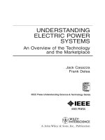
Chapter II. Overview of DC motors
2.1. General structure of DC motors.
A DC machine can be either a generator or an electric motor and have the same
construction. The main parts of DC machines are the inductor (stationary part)
and the armature (rotating part).
2.1.1. Stator.
The inductor is called a stator, consisting of a steel core made of cast steel,
which is both a magnetic circuit and a housing and the main magnetic poles with
a field winding (figure 1.1), the current flowing in the field winding so that the
magnetic poles creating a successive alternating polarity. Main magnetic pole
attached to the housing by bolts. In addition DC machines also have a lid,
auxiliary magnetic pole and brush mechanism.
Figure 1.12. Main magnetic pole.
2.2.2. Armature (rotor).
The armature of a DC machine, also known as a rotor, consists of the steel core,
the armature winding, the commutator and the machine shaft.
15
Electric drive project 2
Design a conveyor drive control circuit
Figure 1.13. Rotor steel foil.
Figure 1.14. Electric machine armature winding wire.
a) Winding element; b) Arrangement of winding element.
Armature steel core: The cylinder is made of 0.5 mm thick electrical engineering
steel sheets, coated with insulating coating. The sheets are stamped with
ventilation holes and grooves to place the armature winding.
Armature winding: Consisting of many elements connected in series, placed in
the grooves of the armature to form one or more closed loops. The winding
element is a coil consisting of one or more turns of the wire, two terminals
connected to two commutator plates of the commutator, the two acting sides of
the element placed in two grooves under two magnetic poles of different names.
16
Electric drive project 2
Design a conveyor drive control circuit
Commutator (commutator), also known as a reversing ring, consists of many
swallow-tailed copper plates that are assembled into a cylindrical block,
insulated from each other and from the machine shaft.
Other parts such as machine shaft, cooling fan ...
2.2. Working principle of DC electric motor.
Figure 1.15. Describe the working principle of DC motors.
In figure 1.15 when applying a direct voltage U to two brushes A and B, there is
a current in the armature winding. The conductors ab and cd carrying current in
the magnetic field will be subjected to a reciprocal force to exert a torque on the
rotor, which turns the rotor. The applied force is determined by the left hand rule
(figure 1.15a).
When the armature has been rotated half a turn, the conductor positions ab, cd
change to each other (figure 1.4b), thanks to the commutator that reverses the
current, the direct current is converted to alternating current applied to the
section winding application, keep the applied force constant, so that the force
exerted on the rotor is also in a certain direction, ensuring the motor has a
constant direction of rotation.
2.3. The rated values of the DC motor.
The rated operating mode of machines in general and of DC motors in particular
is the mode of operation under the conditions specified by the manufacturer.
17
Electric drive project 2
Design a conveyor drive control circuit
Such a mode is characterized by the quantities indicated on the machine's label
called the rated quantities.
Rated power Pdm (kW or W).
Rated voltage Udm (V).
Rated current Idm (A).
Rated speed n (rpm).
In addition, the model, excitation method, excitation curren...
Note: Rated capacity indicates the output power of the machine. For a generator
it is the power given at the generator terminal, and for the engine it is the power
given on the top of the motor shaft.
2.4. Classification of DC motors.
Based on the excitation coil, DC motors are of the following types:
Independent magnetic dc motors.
Parallel magnetic dc motors.
Series magnetic dc motor.
One-dimensional motor from the mix.
2.5. Mechanical properties of DC motors.
Figure 1.16. Wiring schematic diagram of an independent dc electric motor.
Mechanical characteristics of the independent magnetic dc motor. When the DC
source has insufficient capacity, the armature circuit and the excitation circuit
are connected to two independent sources. The motor is now called an
independent magnetic dc motor.
We have the following equation for the voltage balance of the armature circuit:
U u = Eu + ( Ru + Rf ) .I u (1)
18
Electric drive project 2
Design a conveyor drive control circuit
Inside:
Uu: Armature voltage, V
Eư: Armature electromotive force, V
R: Armature circuit resistance,
Iư: The current of the armature circuit, A
With: R = r + rcf + rb + rct
r: Armature coil resistance
rcf: auxiliary magnetic coil resistance
rct: compensating coil contact resistance
Electromotive force E of the motor armature is determined by the expression:
P.N
EФ
= KФ
. . = . .ω (2)
2π a
Inside:
P: Number of main magnetic poles
N: Number of active conductors of armature coil
a: Number of parallel branch circuits of the armature coil
Ф: Magnetic flux under one magnetic pole
ω: Angular speed (rad / s)
( P.N )
K=
2π a
: Structure of the engine
From (1) and (2) we have:
ω =
R + Rf
U
− u
.I (3)
KФ
.
KФ
.
The above expression is the equation for the electromechanical property of the
motor
On the other hand, the electromagnetic torque Mđt of the motor is determined
by:
M đt = KФ
. .I u
I =
With
M đt
KФ
.
(4)
replace the value into (3), we have:
ω=
R + Rf
U
− u
.M đt
2
KФ
.
. )
( KФ
(5)
If mechanical and steel losses are ignored, the mechanical torque on the motor
shaft is equal to the electromagnetic torque, we denote M. That is: Mđt = Mcơ =
M
19
Electric drive project 2
Design a conveyor drive control circuit
ω =
R + Rf
U
− u
.M
2
KФ
.
. )
( KФ
(6)
This is the equation for the mechanical properties of an independent dc electric
motor.
Assuming the armature is fully compensated, the flux Ф = const, then the
electromechanical property equations (3) and mechanical property equation (6)
are linear. Their graphs shown in Figure 2 are straight lines.
U
ω=
= ω0
. )
( KФ
According to the graphs, when Iu = 0 or M = 0:
ω0 is called the ideal no-load speed of an independent magnetic dc motor.
Figure 1.17. Electromechanical and mechanical properties of DC motors.
When ω = 0 we have:
I=
U
= I nm
Ru + R f
M = KФ
. .I nm =M
nm
Inm and Mnm are called short-circuit current and short-circuit moment.
In addition property equations (3) and (6) can also be written in the form:
ω=
ω=
U
R
−
.I = ω0 − ∆ω
KФ
.
KФ
.
U
R
−
.M = ω0 − ∆ω
2
KФ
.
. )
( KФ
Inside:
20
Electric drive project 2
Design a conveyor drive control circuit
R = Ru + R f
ω=
∆ω =
U
KФ
.
R
R
.I =
KФ
.
.
( KФ
)
2
.M
∆ω is called the speed deceleration corresponding to the value of M. From the
mechanical property equation, we see that there are 3 parameters affecting the
mechanical properties: motor flux Ф, armature voltage U, part resistance engine
response.
2.6. Methods of controlling DC motors.
- The method of changing the armature resistance
- The method of changing the flux Ф
- Method of changing armature voltage
a. The method of changing the armature resistance.
This is the commonly used method to control the speed of DC motors. armature.
The stiffness of the mechanical characteristic:
∆M ( KФ )
β=
=
∆ω Ru + R f
2
+) We see that the larger the resistance, the smaller β means the steeper and
therefore the softer the mechanical properties.
Ideal no-load speed:
ω 0 =
Uđm
= const
KФđm
.
21
Electric drive project 2
Design a conveyor drive control circuit
Figure 1.18. Motor characteristics of the motor when auxiliary resistance is
change.
Corresponding to Rf = 0, natural hardness βTN has the largest value, so the
natural mechanical property has stiffness greater than all the mechanical
property curves with auxiliary resistance. Thus, when we change the Rf we get a
family of mechanical properties that are lower than natural mechanical
properties. Characteristics of the method:
+) The higher the armature circuit resistance, the greater the property slope, the
softer the mechanical properties, the poorer the speed stability and the greater
the speed error.
+) This method only allows speed adjustment in the area below the rated speed
(only speed change on the down side is allowed).
+) Only applicable to electric motors with small capacity, because energy loss
on auxiliary resistors reduces motor efficiency and is in fact commonly used in
electric motors in cranes.
+) The initial investment cost is cheap but not economical due to the loss of
large auxiliary resistors, not high quality despite very simple control.
b. Armature voltage change method.
Control principle: When keeping the flux constant Ф = Фđm and no auxiliary
resistor is added in the armature circuit (Rf = 0, Rư = const), if the voltage
22
Electric drive project 2
Design a conveyor drive control circuit
applied to the armature is changed (Uu = var) We will get the mechanical
characteristic when voltage changes are parallel lines.
Door hardness mechanical properties:
( KФ )
β=
Ru
2
= βTN = const
Ideal no-load speed:
ω0 =
Uu
≈ Uu
KФ
. đm
Since the motor flux is kept constant, the mechanical property stiffness is also
constant, and the ideal no-load speed depends on the value of the control voltage
Ukk of the system, thus we obtain a family New parallel and lower natural
mechanical properties is the speed control zone is below the rated speed.
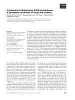
Figure 1.19. Mechanical properties of the motor when changing the
armature slowly.
When the voltage U drops, the starting current I nm that the opening torque of the
Mnm machine decreases and then the speed of the motor decreases with a certain
load. This is the method of limiting Inm and changing engine speed.
Characteristics of the method
23
Electric drive project 2
Design a conveyor drive control circuit
+) The lower the armature voltage, the lower the engine speed.
+) Smooth adjustment throughout the adjustment range.
+) The mechanical hardness is high and is kept constant throughout the
adjustment range.
+) Only change the speed on the down side
+) Very easy to automate when using the rectifier with control.
+) This method controls with constant torque because F and Iu are both constant.
c. The method of changing the flux Ф.
Control principle: Assumption U = U dm, Ru = const. To change the motor flux,
we change the inrush current, change the current in the exciter circuit by
connecting a resistor in series to the exciter circuit or changing the voltage
supplied to the exciter circuit.
Door hardness mechanical properties:
− ( KФ )
β=
≈ Ф2
Ru
2
Ideal no-load speed:
ω0 =
U đm
1
≈
K .Ф Ф
Normally, when the motor operates in the rated mode with maximum excitation
(Ф = Фmax), this method only allows increasing resistance to the inrush circuit, so
it can only be adjusted in the direction of reducing the flux. So when reducing,
the ideal no-load speed ω0 increases, while the mechanical property hardness β
decreases, we get the mechanical properties above the natural mechanical
properties.
24
Electric drive project 2
Design a conveyor drive control circuit
Figure 1.20. Motor characteristics of the motor when the magnetic flux is
changed.
When the motor speed is increased by decreasing the flux, the current increases
and exceeds the permissible value if the torque is constant. Therefore, if we want
to keep the current from exceeding the permissible value at the same time with
the reduction of the flux we have to reduce Mt at the same rate.
Characteristics of the method:
+) This method only controls at the load area not too large compared to the
rating, the change of flux does not change the short-circuit current.
+) Speed adjustment by changing flux is a control method with constant power.
+) This method is applied relatively commonly, can change continuously and
economically (because the speed adjustment is done in the field of excitation
with the excitation current (1 ÷ 10)% Iđm of the armature. low adjustable loss).
This is an almost unique method for DC motors when it is necessary to adjust
the speed greater than the control speed.
Comment: All 3 methods above can adjust the speed of DC motors, but only the
method of adjusting DC motor speed by changing the voltage U set on the motor
armature is best. and is most commonly used because it achieves constant
stiffness, smooth speed regulation and lossless ness.
2.7. Explain the principle of main engine transmission.
* Machine working conditions
- The feeder drive and auxiliary drive are energized (contactor K1 has power).
25