IEEE 802.11 Tutorial pptx
Bạn đang xem bản rút gọn của tài liệu. Xem và tải ngay bản đầy đủ của tài liệu tại đây (568.56 KB, 93 trang )
Mustafa Ergen
June 2002
Department of Electrical Engineering and Computer Science
University of California Berkeley
2
Abstract
This document describes IEEE 802.11 Wireless Local Area Network (WLAN) Standard. It describes IEEE
802.11 MAC Layer in detail and it briefly mentions IEEE 802.11a, IEEE 802.11b physical layer standard and
IEEE 802.11e MAC layer standard.
Acknowledgement
I quoted some of the materials from the “IEEE 802.11 Handbook- A Designer‘s Companion” book. I want to
thank Haiyun Tang for his contribution in finite state machine representations.
Contents
1 Overview 5
1.1 Introduction . . . . . . . . . . . . . . . . . . . . . . . . . . . . . . . . . . . . . . . . . . . . . . . 5
1.1.1 Goals . . . . . . . . . . . . . . . . . . . . . . . . . . . . . . . . . . . . . . . . . . . . . . 5
1.1.2 Architecture . . . . . . . . . . . . . . . . . . . . . . . . . . . . . . . . . . . . . . . . . . 6
2 Medium Access Control 11
2.1 MAC Functionality . . . . . . . . . . . . . . . . . . . . . . . . . . . . . . . . . . . . . . . . . . . 11
2.2 MAC Frame Exchange Protocol . . . . . . . . . . . . . . . . . . . . . . . . . . . . . . . . . . . . 11
2.2.1 Dealing with Media . . . . . . . . . . . . . . . . . . . . . . . . . . . . . . . . . . . . . . 12
2.2.2 The Hidden Node Problem . . . . . . . . . . . . . . . . . . . . . . . . . . . . . . . . . . 12
2.2.3 Retry Counters . . . . . . . . . . . . . . . . . . . . . . . . . . . . . . . . . . . . . . . . . 13
2.2.4 Basic Access Mechanism . . . . . . . . . . . . . . . . . . . . . . . . . . . . . . . . . . . . 14
2.2.5 Timing Intervals . . . . . . . . . . . . . . . . . . . . . . . . . . . . . . . . . . . . . . . . 16
2.2.6 DCF Operation . . . . . . . . . . . . . . . . . . . . . . . . . . . . . . . . . . . . . . . . . 17
2.2.7 Centrally Controlled Access Mechanism . . . . . . . . . . . . . . . . . . . . . . . . . . . 17
2.2.8 Frame Types . . . . . . . . . . . . . . . . . . . . . . . . . . . . . . . . . . . . . . . . . . 20
2.2.9 Control Frame Subtypes . . . . . . . . . . . . . . . . . . . . . . . . . . . . . . . . . . . . 22
2.2.10 Data Frame Subtypes . . . . . . . . . . . . . . . . . . . . . . . . . . . . . . . . . . . . . 24
2.2.11 Management Frame Subtypes . . . . . . . . . . . . . . . . . . . . . . . . . . . . . . . . . 25
2.2.12 Components of the Management Frame Body . . . . . . . . . . . . . . . . . . . . . . . . 27
2.2.13 Other MAC Operations . . . . . . . . . . . . . . . . . . . . . . . . . . . . . . . . . . . . 30
3 MAC Management 36
3.1 Tools Available to Meet the Challenges . . . . . . . . . . . . . . . . . . . . . . . . . . . . . . . 36
3.1.1 Authentication . . . . . . . . . . . . . . . . . . . . . . . . . . . . . . . . . . . . . . . . . 36
3.1.2 Association . . . . . . . . . . . . . . . . . . . . . . . . . . . . . . . . . . . . . . . . . . . 37
3.1.3 Address Filtering . . . . . . . . . . . . . . . . . . . . . . . . . . . . . . . . . . . . . . . . 38
3.1.4 Privacy MAC Function . . . . . . . . . . . . . . . . . . . . . . . . . . . . . . . . . . . . 38
3.1.5 Power Management . . . . . . . . . . . . . . . . . . . . . . . . . . . . . . . . . . . . . . 38
2
3.1.6 Synchronization . . . . . . . . . . . . . . . . . . . . . . . . . . . . . . . . . . . . . . . . 40
3.2 Combining Management Tools . . . . . . . . . . . . . . . . . . . . . . . . . . . . . . . . . . . . 42
3.2.1 Combine Power Saving Periods with Scanning . . . . . . . . . . . . . . . . . . . . . . . . 42
3.2.2 Preauthentication . . . . . . . . . . . . . . . . . . . . . . . . . . . . . . . . . . . . . . . 43
4 MAC Management Information Base 44
4.1 Station Management Attributes . . . . . . . . . . . . . . . . . . . . . . . . . . . . . . . . . . . . 44
4.2 MAC Attributes . . . . . . . . . . . . . . . . . . . . . . . . . . . . . . . . . . . . . . . . . . . . 46
5 The Physical Layer 49
5.1 Physical Layer (PHY) Functionality . . . . . . . . . . . . . . . . . . . . . . . . . . . . . . . . . 49
5.2 Direct Sequence Spread Sp ectrum (DSSS) PHY . . . . . . . . . . . . . . . . . . . . . . . . . . . 49
5.2.1 DSSS PLCP Sublayer . . . . . . . . . . . . . . . . . . . . . . . . . . . . . . . . . . . . . 49
5.2.2 Data Scrambling . . . . . . . . . . . . . . . . . . . . . . . . . . . . . . . . . . . . . . . . 51
5.2.3 DSSS Modulation . . . . . . . . . . . . . . . . . . . . . . . . . . . . . . . . . . . . . . . 51
5.2.4 Barker Spreading Method . . . . . . . . . . . . . . . . . . . . . . . . . . . . . . . . . . . 52
5.2.5 DSSS Operating Channels and Transmit Power Requirements . . . . . . . . . . . . . . . 52
5.3 The Frequency Hopping Spread Spectrum (FHSS) PHY . . . . . . . . . . . . . . . . . . . . . . 53
5.3.1 FHSS PLCP Sublayer . . . . . . . . . . . . . . . . . . . . . . . . . . . . . . . . . . . . . 53
5.3.2 PSDU Data Whitening . . . . . . . . . . . . . . . . . . . . . . . . . . . . . . . . . . . . 54
5.3.3 FHSS Modulation . . . . . . . . . . . . . . . . . . . . . . . . . . . . . . . . . . . . . . . 55
5.3.4 FHSS Channel Hopping . . . . . . . . . . . . . . . . . . . . . . . . . . . . . . . . . . . . 55
5.4 Infrared (IR) PHY . . . . . . . . . . . . . . . . . . . . . . . . . . . . . . . . . . . . . . . . . . . 56
5.4.1 IR PLCP Sublayer . . . . . . . . . . . . . . . . . . . . . . . . . . . . . . . . . . . . . . . 57
5.4.2 IR PHY Modulation Method . . . . . . . . . . . . . . . . . . . . . . . . . . . . . . . . . 59
5.5 Geographic Regulatory Bodies . . . . . . . . . . . . . . . . . . . . . . . . . . . . . . . . . . . . 59
6 Physical Layer Extensions to IEEE 802.11 60
6.1 IEEE 802.11a - The OFDM Physical Layer . . . . . . . . . . . . . . . . . . . . . . . . . . . . . 60
6.1.1 OFDM PLCP Sublayer . . . . . . . . . . . . . . . . . . . . . . . . . . . . . . . . . . . . 60
6.1.2 Data Scrambler . . . . . . . . . . . . . . . . . . . . . . . . . . . . . . . . . . . . . . . . . 61
6.1.3 Convolutional Encoding . . . . . . . . . . . . . . . . . . . . . . . . . . . . . . . . . . . . 62
6.1.4 OFDM Modulation . . . . . . . . . . . . . . . . . . . . . . . . . . . . . . . . . . . . . . . 62
6.1.5 OFDM Operating Channels and Transmit Power Requirements . . . . . . . . . . . . . . 63
6.1.6 Geographic Regulatory Bodies . . . . . . . . . . . . . . . . . . . . . . . . . . . . . . . . 63
6.2 IEEE 802.11b-2.4 High Rate DSSS PHY . . . . . . . . . . . . . . . . . . . . . . . . . . . . . . . 64
6.2.1 HR/DSSS PHY PLCP Sublayer . . . . . . . . . . . . . . . . . . . . . . . . . . . . . . . 64
6.2.2 High Rate Data Scrambling . . . . . . . . . . . . . . . . . . . . . . . . . . . . . . . . . . 65
6.2.3 IEEE 802.11 High Rate Operating Channels . . . . . . . . . . . . . . . . . . . . . . . . . 66
6.2.4 IEEE 802.11 DSSS High Rate Modulation and Data Rates . . . . . . . . . . . . . . . . 66
3
6.2.5 Complementary Code Keying (CCK) Modulation . . . . . . . . . . . . . . . . . . . . . . 66
6.2.6 DSSS Packet Binary Convolutional Coding . . . . . . . . . . . . . . . . . . . . . . . . . 66
6.2.7 Frequency Hopped Spread Spectrum (FHSS)Inter operability . . . . . . . . . . . . . . . 66
7 System Design Considerations for IEEE 802.11 WLANs 67
7.1 The Medium . . . . . . . . . . . . . . . . . . . . . . . . . . . . . . . . . . . . . . . . . . . . . . 67
7.2 Multipath . . . . . . . . . . . . . . . . . . . . . . . . . . . . . . . . . . . . . . . . . . . . . . . . 67
7.3 Multipath Channel Model . . . . . . . . . . . . . . . . . . . . . . . . . . . . . . . . . . . . . . . 68
7.4 Path Loss in a WLAN System . . . . . . . . . . . . . . . . . . . . . . . . . . . . . . . . . . . . . 68
7.5 Multipath Fading . . . . . . . . . . . . . . . . . . . . . . . . . . . . . . . . . . . . . . . . . . . . 69
7.6 Es/No vs BER Performance . . . . . . . . . . . . . . . . . . . . . . . . . . . . . . . . . . . . . . 69
7.7 Data Rage vs Aggregate Throughput . . . . . . . . . . . . . . . . . . . . . . . . . . . . . . . . . 69
7.8 WLAN Installation and Site Survey . . . . . . . . . . . . . . . . . . . . . . . . . . . . . . . . . 70
7.9 Interference in the 2.4 GHz Frequency Band . . . . . . . . . . . . . . . . . . . . . . . . . . . . . 70
7.10 Antenna Diversity . . . . . . . . . . . . . . . . . . . . . . . . . . . . . . . . . . . . . . . . . . . 70
8 IEEE 802.11 PROTOCOLS 72
8.1 Overview of IEEE 802.11 Standards . . . . . . . . . . . . . . . . . . . . . . . . . . . . . . . . . 72
8.2 IEEE 802.11E MAC PROTOCOL . . . . . . . . . . . . . . . . . . . . . . . . . . . . . . . . . . 74
8.2.1 Enhanced Distribution Coordination Function . . . . . . . . . . . . . . . . . . . . . . . . 74
8.2.2 Hybrid Coordination Function . . . . . . . . . . . . . . . . . . . . . . . . . . . . . . . . 76
A 802.11 Frame Format 78
A.1 MAC Frame Formats . . . . . . . . . . . . . . . . . . . . . . . . . . . . . . . . . . . . . . . . . . 78
A.1.1 General Frame Format . . . . . . . . . . . . . . . . . . . . . . . . . . . . . . . . . . . . . 78
A.1.2 Frame Fields . . . . . . . . . . . . . . . . . . . . . . . . . . . . . . . . . . . . . . . . . . 78
A.2 Format of individual frame types . . . . . . . . . . . . . . . . . . . . . . . . . . . . . . . . . . . 79
A.2.1 Control frames . . . . . . . . . . . . . . . . . . . . . . . . . . . . . . . . . . . . . . . . . 79
A.2.2 Data Frames . . . . . . . . . . . . . . . . . . . . . . . . . . . . . . . . . . . . . . . . . . 80
A.2.3 Management frames . . . . . . . . . . . . . . . . . . . . . . . . . . . . . . . . . . . . . . 80
A.3 Management frame body components . . . . . . . . . . . . . . . . . . . . . . . . . . . . . . . . 83
A.3.1 Fixed Fields . . . . . . . . . . . . . . . . . . . . . . . . . . . . . . . . . . . . . . . . . . . 83
A.3.2 Information Elements . . . . . . . . . . . . . . . . . . . . . . . . . . . . . . . . . . . . . 85
B IEEE 802.11a Physical Layer Parameters 87
B.1 Introduction . . . . . . . . . . . . . . . . . . . . . . . . . . . . . . . . . . . . . . . . . . . . . . . 87
B.2 IEEE 802.11a OFDM PHY . . . . . . . . . . . . . . . . . . . . . . . . . . . . . . . . . . . . . . 87
4
Chapter 1
Overview
1.1 Introduction
• In 1997, the IEEE adopted the first standard for WLANs and revised in 1999.
• IEEE defines a MAC sublayer, MAC management protocols and services, and three physical (PHY)
layers.
• PHY Layers:
1. IR at baseband with 1-2 Mbps,
2. FHSS at 2.4GHz with 1-2 Mbps,
3. DSSS at DSSS with 1-2 Mbps.
• IEEE 802.11a ; PHY Layer - OFDM at UNII bands with 54 Mbps
• IEEE 802.11b ; PHY Layer - DSSS at 2.4 GHz with 11Mbps
1.1.1 Goals
• to deliver services previously found only in wired networks.
• high throughput
• highly reliable data delivery
• continuous network connection.
5
1.1.2 Architecture
Architecture is designed to support a network where mobile station is responsible for the decision making.
Advantages are
• very tolerant of faults in all of the WLAN equipment.
• eliminates any possible bottlenecks a centralized architecture would introduce.
Architecture has power-saving modes of operation built into the proto col to prolong the battery life of
mobile equipment without losing network connectivity.
Components
Station the component that connects to the wireless medium. Supported services are authentication, deau-
thentication, privacy, and delivery of the data.
Basic Service Set A BSS is a set of stations that communicate with one another. A BSS does not generally
refer to a particular area, due to the uncertainties of electromagnetic propagation. When all of the
stations int the BSS are mobile stations and there is no connection to a wired network, the BSS is
called independent BSS (IBSS). IBSS is typically short-lived network, with a small number of stations,
that is created for a particular purpose. When a BSS includes an access point (AP), the BSS is called
infrastructure BSS.
When there is a AP, If one mobile station in the BSS must communicate with another mobile station,
the communication is sent first to the AP and then from the AP to the other mobile station. This
consume twice the bandwidth that the same communication. While this appears to be a significant
cost, the benefits provided by the AP far outweigh this cost. One of them is, AP buffers the traffic of
mobile while that station is operating in a very low power state.
Extended Service Set (ESS) A ESS is a set of infrastructure BSSs, where the APs communicate among
themselves to forward traffic from one BSS to another and to facilitate the movement of mobile stations
from one BSS to another. The APs perform this communication via an abstract medium called the
distribution system (DS). To network equipment outside of the ESS, the ESS and all of its mobile
stations appears to be a single MAC-layer network where all stations are physically stationary. Thus,
the ESS hides the mobility of the mobile stations from everything outside the ESS.
Distribution System the distribution system (DS) is the mechanism by which one AP communicates with
another to exchange frames for stations in their BSSs, forward frames to follow mobile stations from
one BSS to another, and exchange frames with wired network.
Services • Station Services: Authentication, De-authentication, privacy, delivery of data
• Distribution Services: Association, Disassociation, Reassociation, Distribution, Integration
6
Station Services Similar functions to those that are expected of a wired network. The wired network func-
tion of physically connecting to the network cable is similar to the authentication and de-authentication
services. Privacy is for data security. Data delivery is the reliable delivery of data frames from the
MAC in one station to the MAC in one or more other station, with minimal duplication and minimal
ordering.
Distribution Services provide services necessary to allow mobile stations to roam freely within an ESS
and allow an IEEE 802.11 WLAN to connect with the wired LAN infrastructure. A thin layer between
MAC and LLC sublayer that are invoked to determine how to forward frames within the IEEE 802.11
WLAN and also how to deliver frames from the IEEE 802.11 WLAN to network destinations outside of
the WLAN.
• The association service makes a logical connection between a mobile station and an AP. It is
necessary for DS to know where and how to deliver data to the mobile station. the logical connection
is also necessary for the AP to accept data frames from the mobile station and to allocate resources
to support the mobile station. The association service is invoked once, when the mobile station
enters the WLAN for the first time, after the application of power or when rediscovering the WLAN
after being out of touch for a time.
• The reassociation service includes information about the AP with which a mobile station has been
previously associated. Mobile station uses repeatedly as it moves in ESS and by using reassocia-
tion service, a mobile station provides information to the AP with which the mobile station was
previously associated, to obtain frames.
• The disassociation service is used to force a mobile station to associate or to inform mobile station
AP is no longer available. A mobile may also use the disassociation service when it no longer
require the services of the AP.
• An AP to determine how to deliver the frames it receives uses the distribution service. AP invoke
the distribution service to determine if the frame should be sent back into its own BSS, for delivery
to a mobile station that is associated with the AP, or if the frame should be sent into the DS for
delivery to another mobile station associated with a different AP or to a network destination.
• The integration service connects the IEEE 802.11 WLAN to other LANs, The integration service
translates IEEE 802.11 frames to frames that may traverse another network, and vice versa.
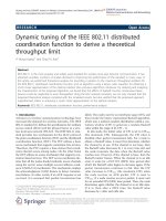
Interaction between Some Services The IEEE 802.11 standard states that each station must maintain
two variables that are dependent on the authentication, de-authentication services and the association,
reassociation, disassociation services. The variables are authentication state and association state and
used in a simple state machine that determines the order in which certain services must be invoked and
when a station may begin using the data delivery service. A station may be authenticated with many
different stations simultaneously. However, a station may be associated with only one other station at
a time.
7
In state 1, the station may use a very limited number of frame types. This frames are to find an
IEEE 802.11 WLAN, an ESS, and its APs, to complete the required frame handshake protocols, and to
implement the authentication service. If a station is part of an IBSS, it is allowed to implement the data
service in state 1. In state2, additional frame types are allowed to provide the capability for a station
in state 2 to implement the association, reassociation, and disassociation services. In state 3, all frame
types are allowed and the station may use the data delivery service. A station must react to frames it
receives in each of the states, even those that are disallowed for a particular state. A station will send a
deauthentication notification to any station with which it is not authenticated if it receives frames that
are not allowed in state 1. A station will send a disassociation notification to any station with which it
is authenticated, but not associated, if it receives frames not allowed in state 2. These notifications will
force the station that sent the disallowed frames to make a transition to the proper state in the state
diagram and allow it to proceeed properly toward state 3.
8
STATE 1:
Unauthenticated
Unassociated
STATE 2:
Authenticated
Unassociated
STATE 3:
Authenticated
Unassociated
DeAuthentication
Notification
Successful
Authentication
Successful
Authentication
or
Reassociation
Disassociation
Notification
Class 1
Frames
Class 1 & 2
Frames
Class 1,2 & 3
Frames
DeAuthentication
Notification
Figure 1.1: Relationship between State Variables and Services
9
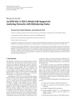
AP1
AP2
AP3
a
b
c
e
f
d
(a) The station finds AP1, it will authenticate and associate.
(b) As the station moves, it may pre-authenticate with AP2.
(c) When the association with AP1 is no longer desirable, it may reassociate with AP2.
(d) AP2 notify AP1 of the new location of the station, terminates the previous association with AP1.
(e) At some point, AP2 may be taken out of service. AP2 would disassociate the associated stations.
(f) The station find another access point and authenticate and associate.
Figure 1.2: Relationship between State Variables and Services
10
Chapter 2
Medium Access Control
MAC protocol supplies the functionality required to provide a reliable delivery mechanism for user data over
noisy, unreliable wireless media.
2.1 MAC Functionality
• reliable data delivery
• fairly control access to the shared wireless medium.
• protect the data that it delivers.
2.2 MAC Frame Exchange Protocol
• noisy and unreliable medium
• frame exchange protocol
• adds overhead to IEEE 802.3
• hidden node problem
• requires participation of all stations.
• every station reacts to every frame it receives.
11
2.2.1 Dealing with Media
The minimal MAC frame exchange protocol consists of two frames, a frame sent from the source to the
destination and an acknowledgment from the destination that the frame was received correctly. if the source
does not get acknowledgement, it tries to transmit according to the basic access mechanism described below.
This reduces the inherent error rate of the medium, at the expense of additional bandwidth consumption
without needing higher layer protocols. Since higher layer timeouts are often measured in seconds, it is much
more efficient to deal with this issue at the MAC layer.
2.2.2 The Hidden Node Problem
A problem that does not occur on a wired LAN. According to their transmission ranges; A and C can not
hear each other and if they transmit at the same time to B, their frames could be corrupted.
A
B
C
Figure 2.1: The Hidden Node Problem
IEEE 802.11 MAC frame exchange protocol addresses this problem by adding two additional frames to
the minimal frame exchange protocol described so far. The two frames are a request to send (RTS) frame
and a clear to send (CTS) frame. Source sends RTS and destination replies with CTS and nodes that here
RTS and CTS susp ends transmission for a specified time indicated in the RTS/CTS frames. See Figure 2.2.
These frames are atomic unit of the MAC protocol. Stations that hear RTS delay transmitting until CTS
frame. It does not hear CTS, it transmits and The stations that here CTS suspend transmission until they
hear acknowledgement.
In the source station, a failure of the frame exchange protocol causes the frame to be retransmitted. This
is treated as a collision, and the rules for scheduling the retransmission are described in the section on the
basic access mechanism. To prevent the MAC from being monopolized attempting to deliver a single frame,
there are retry counters and timers to limit the lifetime of a frame.
12
A
B
C
RTS
CTS
Area cleared after RTS
Area cleared after CTS
Figure 2.2: RTS and CTS address the Hidden Node Problem
RTS/CTS mechanism can be disabled by an attribute in the management information base (MIB). The
value of the dot11RTSThreshold attribute defines the length of a frame that is required to be preceded by the
request to send and clear to send frames.
Where RTS/CTS can be disabled;
• low demand for bandwidth
• where the stations are concentrated in an area where all are able to hear the transmissions of every
station.
• where there is not much contention for the channel.
Default value of the threshold is 128 and by definition, an AP is heard by all stations in its BSS and will
never be a hidden node. When AP is colocated and sharing a channel, the value for the RTS can be changed.
2.2.3 Retry Counters
Two retry counters associated with every frame the MAC attempts to transmit: a short retry counter and a
long retry counter. There is also a lifetime timer associated with every frame the MAC attempts to transmit.
Between these counters and the timer, the MAC may determine that it may cancel the frame‘s transmission
and discard the frame. Then MAC indicates to the MAC user through the MAC service interface. Fewer
tries for the shorter frames as compared to longer frames which is determined from the value of an attribute
in the MIB, dot11RTSThreshold. These counters are incremented in each unsuccessful transmission. When
they reach the limit associated in MIB(dot11ShortRetryLimit, dot11LongRetryLimit) they are discarded.
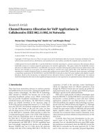
Figure 2.3 explains in detail.
13
PHY_TXEND.conf
Last frame needs
Ack?
Ack Timer
YES
Receive
PHY_RXSTART.ind
before timeout
Wait frame
end
Receive
PHY_RXEND.ind
Valid Ack?
Single-cast
data or RTS
YES
CW = aCWmin
SRC = 0 (LRC = 0 if
frame len >
aRTSThreshold)
CW = MAX(CW*2+1,
aCWmax)
SRC++ (or LRC++)
Timeout and
and didn't receive
PHY_RXSTART.ind
NO
SRC (or LRC) limit
reached?
Backoff
Discard frame
CW = aCWmin
SRC (or LRC) = 0
NO
YES
PHY_RXSTART.ind PHY_RXEND.ind
Further Tx
sequence
TxWait SIFS
YES
Retransmission
NO
Packet
Fragments
or
RTS+CTS+Data
YES
Figure 2.3: Frame Sequence and Retry Procedure Finite State Representation
2.2.4 Basic Access Mechanism
The basic access mechanism is carrier sense multiple access with collision avoidance (CSMA/CA) with binary
exponential backoff similar to IEEE 802.3, with some significant exceptions. CSMA/CA is a “listen before
talk” (LBT) access mechanism. When there is a transmission in the medium, the station will not begin its own
transmission. This is the CSMA portion of the access mechanism. If there is a collision and the transmission
corrupted, the operation of the access mechanism works to ensure the correct reception of the information
transmitted on the wireless medium.
BackoffIdle
Tx
Sequence
& Retry
Busy
During Tx
Medium not busy
during Tx attempt
Finish Tx
Still in sequence
and last step successful
Pre-Tx backoff
successful
Just Transmitted
Ack or CTS
All other transmitted frames
whether successful or not
Post-Tx backoff successful
PCS
VCS
Wait
Idle for
IFS time
Busy during backoff
Figure 2.4: MACRO Finite State Representation
As IEEE 802.11 implements this access mechanism, when a station listens to the medium before beginning
its own transmission and detects an existing transmission in progress, the listening station enters a wait
14
PAV ("lastPCSBusyTime")
NAV ("lastVCSBusyTime")
currentTime
packetToSend
Note: PAV = (lastPHY_CCA == IDLE) ? lastPHY_CCATime : currentTime
System Fields:
Queue
empty?
LLC or MAC
MAC Packet Queue
PCS
VCS
Wait
currentTime >
MAX(PAV, NAV)
Tx
YES
NO
YES
NO
Packet Add Trigger
Packet size >
RTSThreshold &&
FragNum == 0
packetToSend =
RTS
packetToSend =
dequeued data
packet
YES
NO
Figure 2.5: IDLE Procedure Finite State Representation
period determined by the binary exponential backoff algorithm (See Figure 2.6). It will also increment the
appropriate retry counter associated with the frame. The binary exponential backoff mechanism chooses a
random number which represents the amount of time that must elapse while there are not any transmissions,
i.e., the medium is idle before the listening station may attempt to begin its transmission again. The random
number resulting from this algorithm is uniformly distributed in a range, called the contention window, the
size of which doubles with every attempt to transmit that is deferred, until a maximum size is reached for
the range. Once a transmission is successfully transmitted, the range is reduced to its minimum value for the
next transmission.
Enter backoff
BC =
Rand() & CW
CW = 2
N
-1
Wait 1 TS
PAV
NAV
currentTime
BC (Backoff counter)
TS = 1 slot time = 20 (802.11b), 9 (802.11a)
System Fields:
MAX(PAV, NAV)
< currentTime - TS
YES
YES
Leave backoff
NO
PCS
VCS
Wait
NO
BC == 0? BC == 0?
BC
NO
Idle for IFS Time
Enter backoff
YES
Figure 2.6: BACKOFF Procedure Finite State Representation
It is extremely unusual for a wireless device to be able to receive and transmit simultaneously, the IEEE
802.11 MAC uses collision avoidance rather than the collision detection of IEEE 802.3. It is also unusual for
all wireless devices in LAN to be able to communicate directly with all other devices. For this reason, IEEE
802.11 MAC implements a network allocation vector (NAV). The NAV is a value that indicates to a station
the amount of time that remains before the medium will become available. Even if the medium does not
15
Packet is
RTS?
currentIFSTime
lastRxStartTime
lastRxEndTime
currentTime
NAV
T = 2*aSIFSTIme + CTSTime + 2*aSlotTime
currentTime +
Packet Duration >
NAV
Update
NAV
Count
down on
T
lastRxEndTime >
lastRxStartTime
Packet
Correct?
currentIFSTime =
EIFS
NO
YES
currentIFSTime =
DIFS
NAV =
currentTime +
Packet Duration
Expired
currentTime -
lastRxEndTime >= T
YES
YES
YES
PHY_RXEND.ind
NAV =
currentTi
me
STA is
packet
addressee
NO
System Fields:
lastRxStartTime =
currentTime
lastRxEndTime =
currentTime
PHY_RXSTART.ind PHY_RXEND.ind
PHY_CCARESET.req
Packet
needs Ack?
TxWait SIFS
YES
YES
Figure 2.7: NAV Procedure Finite State Representation
appear to be carrying a transmission by the physical carrier sense, the station may avoid transmitting. The
NAV, then, is a virtual carrier sensing mechanism. By combining the virtual carrier sensing mechanism with
the physical carrier sensing mechanism(See Figure 2.7), the MAC implements the collision avoidance portion
of the CSMA/CA access mechanism.
2.2.5 Timing Intervals
There are five timing intervals.
1. PHY determines: the short interframe space (SIFS)
2. PHY determines: the slot time.
3. the priority interframe space (PIFS),
4. the distributed interframe space (DIFS),
5. and the extended interframe space (EIFS).
The SIFS is the shortest interval, followed by the slot time which is slightly longer. The PIFS is equal to
SIFS plus one slot time. The DIFS is equal to the SIFS plus two slot times. The EIFS is much larger than
any of the other intervals. It is used when a frame that contains errors is received by the MAC, allowing
the possibility for the MAC frame exchanges to complete correctly before another transmission is allowed.
Through these five timing intervals, both the DCF and PCF are implemented.
16
2.2.6 DCF Operation
The basic 802.11 MAC protocol is the DCF based on CSMA. Stations deliver MAC Service Data Units
(MSDUs). Stations deliver MSDUs of arbitrary lengths up to 2304 bytes, after detecting that there is no
other transmission in progress on the channel. However, if two stations detect the channel as free at the same
time, a collision occurs. The 802.11 defines a Collision Avoidance (CA) mechanism to reduce the probability
of such collisions. Before starting a transmission a station has to keep sensing the channel for an additional
random time after detecting the channel as being idle for a minimum duration called DIFS, which is 34 us
for the 802.11a PHY. Only if the channel remains idle for this additional random time period, the station is
allowed to initiate its transmission. Figure 2.4 represent the finite state machine of DCF operation. When
the station has packet to transmit, it senses the channel by Physical Carrier Sense(PCS) and Virtual Carrier
Sense(VCS). PCS notifies the MAC layer if there is a transmission going on and VCS is NAV procedure,
If NAV is set to a number, station waits untill it resets to zero. After carrier sensing, station backoffs and
transmit the data. If there is a collision, corresponding retry counter increments and backoff interval increases.
In every transmission station backoffs, this is put into standard in order to provide fairness among the stations.
1. when the MAC receives a request to transmit a frame, a check is made of the physical and virtual carrier
sense mechanisms.
2. if the medium is not in use for an interval of DIFS (or EIFS if the pre-received frame is contained errors),
the MAC may begin transmission to the frame.
3. if the medium is in use during the DIFS interval, the MAC will select a backoff and increment the retry
counter.
4. The MAC will decrement the backoff value each time the medium is detected to be idle for an interval
of one slot time.
5. it there is a collision, the contention window is doubled, a new backoff interval is selected2.6.
An example of a DCF operation is seen in Figure 2.8.
2.2.7 Centrally Controlled Access Mechanism
Uses a poll and response protocol to eliminate the possibility of contention for the medium. This access
mechanism is called PCF. A point coordinator (PC) controls the PCF. The PC is always located in an AP
(See Figures 2.9 and 2.10). Generally, the PCF operates by stations requesting that the PC register them
on a polling list, and the PC then regularly polls the stations for traffic while also delivering traffic to the
stations. The PCF is built over the DCF and both operate simultaneously. The PCF uses PIFS instead of
DIFS. The PC begins a period of operation called the contention-free period (CFP), during which the PCF is
operating. This period is called contention free because access to the medium is completely controlled by the
PC and the DCF is prevented from gaining access to the medium. The CFP occurs periodically to provide a
17
Station sets NAV upon receiving RTS
Station sets NAV upon receiving
CTS, this station is hidden to
station 1
Station 1
NAV
NAV
Station sets NAV upon receiving RTS
Station 6
Station 5
Station 4
Station 3
Station 2
RTS
S
I
F
S
NAV
NAV
NAV
S
I
F
S
S
I
F
S
S
I
F
S
S
I
F
S
D
I
F
S
D
I
F
S
D
I
F
S
D
I
F
S
random
backoff
(7 slots)
new random
backoff
(10 slots)
random
backoff
(9 slots)
remaining
backoff
(2 slots)
CTS
ACK
ACK
ACK
DATA
DATA
Station defers, but keeps backoff counter (=2)
Station defers
time
DATA
Figure 2.8: Timing of the 802.11 DCF. In this example, station 6 cannot detect the RTS frame of the
transmitting station 2, but the CTS frame of station 1.
near-isochronous service to the stations. The CFP also alternates with a contention period where the normal
DCF rules operate and all stations may compete for access to the medium. The standard requires that the
contention period be long enough to contain at least one maximum length frame and its acknowledgement.
CP
(DCF
MODE)
CFP
(PCF
MODE)
Sense the
medium
for
PIFS
Yes
Adjust
CFP
Time
CFPDurRemaining=
TBTT+CFPMaxDuration
CPTime+CFPTime= CFPRate
PCF MACRO STATE
If
Delay
Figure 2.9: PCF MACRO Finite State Representation of Access Point
The CFP begins when the PC gains access to the medium, using the normal DCF procedures, and
transmits a Beacon frame. Beacon frames are required to be transmitted periodically for PC to compete for
the medium. The traffic in the CFP will consists of frames sent from the PC to one or more stations, followed
by the acknowledgement from those stations. In addition, PC sends a contention-free-poll (CF-Poll) frame
to those stations that have requested contention-free service (See Figures 2.11 and 2.12). If the station has
18
A
P
P
o
i
n
t
i
n
C
F
P
P
e
r
i
o
d
S
e
n
t
B
e
a
c
o
n
+
D
T
I
M
D
a
t
a
SIFS
C
F
-
E
n
d
+
A
C
K
No
PIFS
No
Yes
Yes
and
received DATA
CFP is Null
SIFS
Yes
Wait for
ACK
Check
_________________________
1) No Frames to send
2) No STA to poll
3) CFPDurRemaining elapsed
Data
+CF-Poll
No
Poll in ascending AID
Check
Polling
List
Poll in ascending AID
No
TX-1
_____________________
1) Data+CF-Poll
2) Data+CF-ACK+CF-Poll
3) CF-Poll
4) CF-ACK+CF-Poll
TX-2
_______________
1) Data
2) Data+CF-ACK
3) CF+ACK
4) Management
Check
Polling List
TX-2
TX-1
CF-End
Check
Figure 2.10: CFP Period Finite State Representation of Access Point
data to send then respond to CF-Poll. For medium efficient utilization, it is possible to piggyback both the
acknowledgement and the CF-Poll onto data frames.
During the CFP, the PC ensures that the interval between frames to the medium is no longer than PIFS
to prevent a station operating under the DCF from gaining access to the medium. Until CFP, PC sends in
SIFS and waits for response for SIFS and tries again.
NAV prevents stations from accessing the medium during the CFP. Beacon contains the information about
maximum expected length of the CFP. The use of PIFS for those who did not receive beacon. PC announces
the end of the CFP by transmitting a contention-free end (CF-End) Frame. It resets NAV and stations begin
operation of DCF, independently.
There are problems with the PCF that led to the current activities to enhance the protocol. Among many
others, those include the unpredictable beacon delays and unknown transmission durations of the polled
stations. At TBTT target beacon transmission time (TBTT), a PC schedules the beacon as the next frame
to be transmitted, and the beacon can be transmitted when the medium has been determined to be idle for
at least PIFS. Depending on the wireless medium at this point of time, i.e., whether it is idle or busy around
the TBTT, a delay of the beacon frame may occur. The time the beacon frame is delayed, i.e., the duration
it is sent after the TBTT, delays the transmission of time-bounded MSDUs that have to be delivered in CFP.
From the legacy 802.11 standard, stations can start their transmissions even if the MSDU Delivery cannot
finish before the upcoming TBTT [3]. This may severely affect the QoS as this introduces unpredictable time
delays in each CFP. Beacon frame delays of around 4.9ms are possible in 802.11a in the worst case.
19
2.2.8 Frame Types
MAC accepts MSDUs from higher layers and add headers and trailers to create MPDU. The MAC may
fragment MSDUs into several frames, increasing the probability of each individual frame being delivered
successfully. Header+MSDU+Trailer contains information;
• addressing information
• IEEE 802.11-specific protocol information
• information for setting the NAV
• frame check sequence for verifying the integrity of the frame.
General Frame Format
FC D/ID Addr.
1
Addr.
2
Addr.
3
Seq
Cont.
Addr.
4
Data FCS
2 2 6 6 6 2 6 0-2312 4 bytes
FC - Frame Control: 16bits
1. Protocol Version: 2 bits; to identify the version of the IEEE 802.11 MAC protocol: set to zero now.
2. Frame Type and Sub Type: identifies the function of the frame and which other MAC header fields
are present in the frame. Within each frame types there may be subparts.
3. To DS and From DS: To DS is 1bit length; Set every data sent from mobile station to the AP. Zero
for all other frames. From DS is 1 bit again and for the data types from AP to the mobile station.
When both zero that means a direct communication between two mobile stations. When both are
on, for special case where an IEEE 802.11 WLAN is being used as the DS refeered as wireless DS.
The frame is being sent from one AP to another, over the wireless medium.
4. More Fragments Subfield: 1bit; indicates that this frame is not the last fragment of a data or
management frame.
5. Retry Subfield: 1bit; when zero, the frame is transmitted for the first time, otherwise it is a
retransmission.
6. Power Management Subfield: 1bit;mobile station announces its power management state; 0 means
station is in active mode and 1 means the station will enter the power management mode. The
subfield should be same during the frame exchange in order for the mobile to change its power
management mode. Frame exchange is 2or 4 way frame handshake including the ACK.
7. More Data Subfield: 1bit; AP uses to indicate to a mobile station that there is at least one frame
buffered at the AP for the mobile station. Mobile polled by the PC during a CFP also may use this
subfield to indicate to the PC that there is at least one more frame buffered at the mobile station
to be sent to the PC. In multicast , AP may also set to indicate there are more multicast frames.
20
8. WEP Subfield: 1bit; 1 indicates that the frame bo dy of MAC frame has been encrypted using
WEP algorithm.(only data and management frames os subtype authentication)
9. Order Subfield: 1bit; indicates that the content of the data frame was provided to the MAC with
a request for strictly ordered service. provides information to the AP and DS to allow this service
to be delivered.
Duration/ID Field (D/ID): 16bits; alternatively contains information for NAV or a short ID(association
ID-AID)used mobile station to get its buffered frames at the AP. only power-save poll (PS-Poll) frame
contains the AID. most two significant bit is set to 1 and the rest contains ID. All values larger than
2007 are reserved.
When 15bit is zero the rest (14-0) represents the remaining duration of a frame exchange to update
NAV. The value is set to 32,768(15bit=1 and the rest 0) in all frames transmitted during the CFP to
allow a station who missed the beginning to recognize that it is in middle of the CFP session and it set
NAV a higher value.
Address Fields: 4 address fields: besides 48bit address (IEEE 802.3) additional address fields are used
(TA,RA,BSSID) to filter multicast frames to allow transparent mobility in IEEE 802.11.
1. IEEE 48bit address comprises three fields:
• a single-bit Individual/Group field: When set to 1, the address is that of a group. if all bit are
1 , that means broadcast.
• a single-bit Universal/Local bit; when zero, the address is global and unique, otherwise it may
no be unique and locally administered.
• 46bit address fields.
2. BSS Identifier (BSSID): unique identifier for a particular BSS. In an infrastructure BSSID it is the
MAC address of the AP. In IBSS, it is random and locally administered by the starting station.
This also give uniqueness. In the probe request frame and group address can be used.
3. Transmitter Address (TA): MAC address of the station that transmit the frame to the wireless
medium. Always an individual address.
4. Receiver Address (RA): to which the frame is sent over wireless medium. Individual or Group.
5. Source Address (SA): MAC address of the station who originated the frame. Always individual
address. May not match TA because of the indirection performed by DS of an IEEE 802.11 WLAN.
SA field is considered by higher layers.
6. Destination Address (DA): Final destination . Individual or Group. May not match RA because
of the indirection.
Sequence Control Field: 16bit: 4bit fragment number and 12bit sequence number. Allow receiving station
to eliminate duplicate received frames.
21
1. Sequence Number Subfield: 12bit; Each MSDU has a sequence number and it is constant. Sequen-
tially incremented for the following MSDUs.
2. Fragment Number Subfield: 4bits; Assigned to each fragment of an MSDU. The firs fragment is
assigned to zero and incremented sequentially.
Frame Body Field: contains the information specific to the particular data or management frames. Variable
length. As long as 2304bytes and when ecrypted 2312bytes. An application may sent 2048byte with
256 byte upper layer headers.
Frame Check Sequence Field: 32 bits; CCITT CRC-32 polynomial:
G(x) = x
32
+ x
26
+ x
23
+ x
22
+ x
16
+ x
12
+ x
11
+ x
10
+ x
8
+ x
7
+ x
5
+ x
4
+ x
2
+ x + 1
The frame check sequence is an IEEE 802 LAN standards and generated in the same way as it is in
IEEE 802.3.
2.2.9 Control Frame Subtypes
Request to Send 20bytes;
• Frame Control Field:
• Duration/ID field:
• RA-always individual address
• TA
• FCS
The purpose is to transmit the duration to stations in order for them to update their NAV to prevent
transmissions from colliding with the data or management frame that is expected to follow. Duration
information conveyed by this frame is a measure of the amount of time required to complete the four-way
frame exchange. Duration (ms)= CTS+Data or management frame+ ACK+ 2 SIFS
Clear to Send: 14bytes;
• Frame Control Field, Duration/ID Field
• RA, individual MAC address
• FCS
for updating the NAV. Duration (ms) =Data or management frame + ACK + 1 SIFS
Acknowledge: 14 bytes;
• Frame Control Field
22