An overview of a long life battery technology nickel iron
Bạn đang xem bản rút gọn của tài liệu. Xem và tải ngay bản đầy đủ của tài liệu tại đây (284.13 KB, 6 trang )
International Journal of Advanced Engineering Research
and Science (IJAERS)
Peer-Reviewed Journal
ISSN: 2349-6495(P) | 2456-1908(O)
Vol-9, Issue-8; Aug, 2022
Journal Home Page Available: />Article DOI: />
An overview of a long-life battery technology: Nickel–iron
Andrianary Lala Raminosoa1, Hery Zo Randrianandraina2, Ravo Ramanantsoa3, Minoson
Rakotomalala4
Institute for the Management of Energy (IME), University of Antananarivo, Madagascar
1Email: ; 2Email: ; 3Email: ; 4Email:
Received: 14 Jul 2022,
Received in revised form: 07 Aug 2022,
Accepted: 11 Aug 2022,
Available online: 15 Aug 2022
©2021 The Author(s). Published by AI
Publication. This is an open access article
under the CC BY license
( />Keywords— Electrochemical storage, lead–
acid, long lifespan, nickel–iron, photovoltaic
cells
I.
Abstract— This survey was designed following the progress of the use of
solar energy. Madagascar is one of the countries that benefit enormously
from this energy. As a result, many Malagasy people use photovoltaic
cells for domestic and professional applications especially those who are
outside the electrified areas. However, the used batteries last only 5 years
or even 10 years at most, hence the idea of updating Thomas Edison's
research in 1901, a nickel–iron battery technology which is distinguished
by its long lifespan of more than 25 years. It is therefore a question of
determining the chemical reactions involved into the battery, its aging
process, its characteristics, its advantages and disadvantages compared to
the lead–acid technology. Once the theoretical studies are carried out, the
study proposes an application of nickel–iron technology in a photovoltaic
installation in Madagascar.
INTRODUCTION
Photovoltaic (PV) solar energy is considered to be the
most flexible of the renewable energy sources due to its
use in almost all power classes ranging from mW to GW
and in most places in the world. However, a PV system
requires a storage unit for the energy produced during the
sunny day(s) to continue to distribute it at night or on days
when the cloud cover is too great for the PV cells to
operate. Batteries not only ensure the appropriate response
time and storage capacity to meet production and grid
needs, but must also show long life and be able to
withstand a large number of charge–discharge cycles:
these are often the most expensive and fragile components
of a solar system. [1, 2]
In this article, we will discuss an energy storage
technology with a long lifespan and of which existence is
little known: it is nickel–iron technology. The nickel–iron
(Ni–Fe) battery is a rechargeable electrochemical power
source which was created in Sweden by Waldemar
Jungner around 1890. By substituting cadmium for iron, he
improved cell performance and efficiency, but he
abandoned its development in favor of nickel–cadmium.
www.ijaers.com
While Thomas Edison believed that the Ni–Fe battery
could replace the lead–acid (Pb–acid) battery, he was
granted his patent in 1901. [3, 4]
The Thomas Edison battery factory in West Orange,
New Jersey, USA, manufactured cells from 1903 to 1972,
when it was sold to Exide Battery Company (its name at
the time) which production continued until 1975, when the
plant closed [3]. The Ni–Fe battery has lost its market
share to the Pb–acid battery [5]. Despite this, besides
Germany, companies such as Kursk Accumulator in
Russia and ChangHong Battery in China still
manufactured Ni–Fe cells [3, 6].
Ni–Fe batteries have been applied to almost all fields in
which they are used. A list of uses [6-8] to which they are
applied include electric trucks, forklifts and industrial
tractors, mining locomotives and industrial, electric road
vehicles, lighting and air conditioning in trains, railway
signaling systems, maritime services, isolated lighting
plants, clocks, the system in lighting and emergency alarm
circuits, miners' capped lamps, power supplies for
instruments and laboratories, communication equipment
and portable lighting units. Finally, the Ni–Fe battery is
Page | 207
Raminosoa et al.
International Journal of Advanced Engineering Research and Science, 9(8)-2022
suitable for storing electrical energy derived from solar
energy via photovoltaic cells [8].
II.
PRINCIPLE OF OPERATION
With regard to the active materials which constitute it,
the Ni–Fe battery is composed of nickel oxyhydroxide as
the positive electrode, iron as the negative electrode and a
solution of potassium hydroxide, with a little lithium
hydroxide added in order to exert a stabilizing effect on the
capacity of the positive electrode during the charge–
discharge cycle, as an electrolyte [9, 10]. These materials
were originally enclosed in rectangular pockets of
perforated thin sheet steel which were attached to steel
frames to form the positive and negative electrodes [7].
The overall reactions that occur at the electrodes ensue
from a transfer of oxygen from one electrode to another. In
general, the Ni–Fe battery is represented by:
( −)
Fe(s) KOH (aq) NiOOH (s)
(+)
AGING PROCESS
3.1 Negative electrode
Iron is an element known since prehistoric times.
Unlike other battery electrode materials such as cadmium,
lead, nickel and zinc, iron electrodes are quite
environmentally friendly. Furthermore, iron electrodes are
both mechanically and electrically robust [11]. Iron has a
high theoretical capacity of around 0.97 Ah.g-1. Depending
on the design and manufacture of the electrodes, there are
three different types of iron electrodes [8] namely pocket
or tubular electrodes, pressed or compacted electrodes and
sintered electrodes.
The charge–discharge reactions at the negative
electrode of a Ni–Fe battery occur in two stages
corresponding to two distinct voltage levels: [8, 11-13]
discharge
Fe + 2OH − ⎯⎯⎯⎯
⎯⎯
⎯→ Fe ( OH ) 2 + 2e −
charge
(E
. [6]
2 NiOOH + Fe + 2 H 2 O ⎯⎯⎯⎯
⎯⎯
⎯→ 2 Ni ( OH )2
charge
(E
0
= 1.37 V )
(E
0
= 1.05V )
(E
(1)
At this stage, the reactions of the cells are highly
reversible. Reaction (1) proceeds under deep discharge. A
Ni–Fe cell will undergo yet another discharge reaction (2),
but with a lower voltage compared to the first stage: [4,
11]
discharge
NiOOH + Fe ( OH )2 ⎯⎯⎯⎯
⎯⎯
⎯→ Ni ( OH )2 + FeOOH
charge
0
= − 0.88V )
discharge
Fe ( OH )2 + OH − ⎯⎯⎯⎯
⎯⎯
⎯→ FeOOH + H 2 O + e −
charge
discharge
+ Fe ( OH )2
III.
(2)
Unlike lead–acid technology, the electrolyte does not
participate in chemical reactions. It is therefore not
possible to determine its state of charge for any
measurement of the density of the electrolyte. [5]
0
= − 0.56 V )
(3)
(4)
Under strong alkaline conditions, the main process
expressed by equation (3) manifests the reduction of
ferrous ions (Fe2+) to metallic iron (FeO) during charging
and vice versa during discharging. In case the Ni–Fe
battery is designed with excess iron, reaction (4) rarely
occurs in the battery. [8, 14]
Equation (3), in its general form, reflects the initial and
final states of the active material [12]. The overall
mechanism of the electrode reaction (3) involves both
solid
(homogeneous
mechanism)
and
liquid
(heterogeneous mechanism) phases with HFeO2– ions as
dissolved intermediates which convert to iron hydroxide
(Fe(OH)2) during a new discharge [11, 13]: the iron is
therefore oxidized into HFeO2– ions, then into porous
Fe(OH)2 [12]. Accordingly, the actual course [11-13] of
the reaction (3) electrodes can be expressed as follows:
Fe + 3OH − → HFeO2− + H 2O + 2e −
(E
0
= −0.748V )
(5)
followed by:
HFeO2− + H 2O → Fe ( OH )2 + OH −
( G
0
298
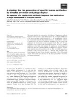
Fig. 1: Schematic representation of the operating principle
of a Ni–Fe cell.
www.ijaers.com
= −24.7 kJ )
(6)
During prolonged discharge, the composition of the
active –FeOOH in iron hydroxide is similar to the
positive electrode in nickel. The electrode reaction
involves the diffusion of protons between the solid lattices
of Fe(OH)2 and –FeOOH. [11]
Page | 208
Raminosoa et al.
International Journal of Advanced Engineering Research and Science, 9(8)-2022
It has been speculated that the formation of magnetite
Fe3O4 in different oxidation states between iron
hydroxides results in the reaction:
Fe ( OH )2 + 2 − FeOOH → Fe3O4 + 2 H 2O
( G
0
298
= −74.9 kJ )
(7)
rather than by an electrochemical process [11].
X–ray phase analysis of the electrodes removed from
the solutions after discharge demonstrated a decrease in
the amount of iron(II) hydroxide formed in the electrodes
during the first anodic process and an increase in
magnetite. Therefore, the conversion of Fe(OH)2 to Fe3O4
is described by the reaction equation: [11]
3Fe ( OH )2 + 2OH − → Fe3O4 + 4 H 2O + 2e −
(E
= −1.22V )
0
(8)
On the other hand, in the case of anodic polarization of
an iron electrode in the range of the first potential plateau
at 328 K, a considerable amount of magnetite is formed
together with the main discharge product Fe(OH)2. A
direct electrochemical conversion of Fe to Fe3O4 has been
estimated: [11]
3Fe + 8OH − → Fe3O4 + 4 H 2O + 8e −
(E
= −0.913V )
0
(9)
Magnetite can also be formed by the following
reactions involving dissolved oxygen in the electrolyte:
[12]
3HFeO2 − + 1 2 O2
Fe3O4 + 3OH −
( G
0
298
3Fe ( OH )2 + 1 2 O2
= −348.8 kJ )
Fe3O4 + 3H 2O
( G
0
298
= −275.0 kJ )
(10)
(11)
3.2 Positive electrode
Used for more than a century, nickel hydroxides
(Ni(OH)2) compose the active material of the positive
electrodes of several alkaline cells. Understanding the
reactions at these electrodes has been very slow due to the
complex nature of the reactions. [16] Its maximum
theoretical capacity is around 0.289 Ah.g-1 [17]. In battery
terms, the nickel electrode is often referred to the nickel
oxide (NiO2) and charge–discharge reactions are expressed
as: [11, 13]
discharge
−
NiO2 + 2 H 2 O + 2e − ⎯⎯⎯⎯
⎯⎯
⎯→ Ni ( OH ) 2 + 2OH
charge
(E
Fe + 2 H 2 O → Fe ( OH )2 + H 2
2 H 2 O + 2e −
H 2 + 2OH −
( G
0
298
(E
0
= −9.3 kJ )
= −0.828V )
(12)
(13)
= 0.49V )
(14)
The nickel oxide forms the active material of the
positive plate with nickel hydroxide as the discharged
product which is recovered as nickel oxide during
recharging. In practice, the discharge product, converted to
beta–nickel oxyhydroxide (–NiOOH) during recharging,
is –Ni(OH)2. Equation (14) becomes: [11, 13, 17, 18]
discharge
− NiOOH + H 2 O + e ⎯⎯⎯⎯
⎯⎯
⎯→ − Ni ( OH ) 2
charge
−
+OH −
(E
0
= 0.49V )
(15)
During charging, –Ni(OH)2 is therefore converted to
–NiOOH by a deprotonation mechanism and the reaction
is reversed during discharging reducing nickel
oxyhydroxide 3+ to nickel hydroxide 2+ by protonation
[17]. The mechanism of reaction (15) involves an
equivalent diffusion of protons through the solid state
lattices of –Ni(OH)2 and –NiOOH so that there is a
continuous change in the composition of the material
active between fully charged –NiOOH and fully
discharged –Ni(OH)2.
Thus, equation (15) can also be written: [11, 13]
discharge
− NiOOH + H + + e ⎯⎯⎯⎯
⎯⎯
⎯→ − Ni ( OH )2
charge
−
Since reaction (8) takes place in the electrolyte, it
results in the formation of a black deposit of magnetite on
the surface of separators and battery reservoirs. Equation
(12) shows the reaction of iron with water and hydrogen
evolution that occurs during charging: [11, 15]
0
(16)
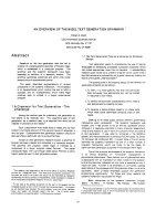
Three crystal modifications of nickel hydroxide appear
as a lattice structure with alternating layers of nickel ions
and hydroxide ions. The starting material for the
transformation of the alkaline electrode is the form. [11]
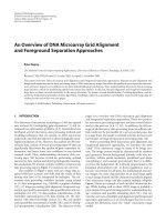
Fig. 2 gives an overview on the structural changes of
nickel hydroxides during charging, discharging,
overcharging and aging (dehydration) [11, 13, 16]
On one side, the hydrogen evolution reaction takes
place since the electrode potential for this reaction is
positive with respect to that of reaction (3) and on the other
side, water is electrochemically decomposed into hydrogen
and hydroxyl ions during charging [14, 15].
www.ijaers.com
Page | 209
Raminosoa et al.
International Journal of Advanced Engineering Research and Science, 9(8)-2022
Fig. 2: Bode reaction diagram showing the various
transformations of a nickel electrode. [11]
The oxidation (charge) voltage of the and
materials, 60 mV and 100 mV respectively, is more positive
than the discharge voltage. The –Ni(OH)2 is the usual
electrode material. Oxidized, it is converted on charge to
–NiOOH with about the same molar volume. In case of
overcharge, the structure can form. This form also
incorporates water and potassium (and lithium) into the
structure. Its molar volume is about 1.5 times the form.
This shape is believed to be largely responsible for the
volume expansion (swelling) which occurs during battery
charging. The form then results on discharge of the
form. Its molar volume is about 1.8 times that of the
form and the electrode can swell further on discharge. On
discharge, the form converts to the form in a
concentrated electrolyte. Additions of cobalt (2 to 5%)
improve the charge acceptance (reversibility) of the nickel
electrode. [5, 13, 16]
IV.
PERFORMANCE CHARACTERISTICS
The theoretical energy density of a Ni–Fe battery, lying
between Ni-Cd (244 Wh.kg-1) and Ni-MH (278 Wh.kg-1), is
268 Wh.kg-1. The practical energy density depends on the
technology used to manufacture the electrodes. It is
between 20 Wh.kg-1 and 30 Wh.kg-1 for tubular electrodes
and can reach 40–60 Wh.kg-1 or even up to 80 Wh.kg-1 [19]
for sintered or fiber electrodes. The open circuit voltage,
discharge voltage and charge voltage of Ni–Fe cells are
1.37 V; 1.3 V at 1.0 V and 1.7 V at 1.8 V, respectively. Its
nominal voltage is 1.2 V. [5, 8, 20]
Constant voltage charging of conventional Ni–Fe cells
which can lead to thermal runaway and cause serious
damage is not recommended. As the cell approaches full
charge, gassing reactions generate heat and the cell
temperature increases: a limited galvanostatic charge of
www.ijaers.com
1.7 V per cell has been shown to be beneficial in
controlling cell temperature. Its discharge capacity
depends on the discharge rate. Indeed, when a nickel–iron
system is discharged at a rate of C/1, the realized capacity
is only 50% of the nominal value and the voltage varies
between 1 V and 0.8 V. Batteries with tubular positive
electrodes are designed for low or moderate discharge
rates i.e. C/8 to C/1 while those with sintered electrodes
can provide high power due to its low internal resistance.
The nominal (operating or discharging) cell voltage
variation is approximately 1.23 V at C/8 rate to 0.85 V at
C/1 rate. The change in cell voltage on a C/8 rate is 1.32 V
to about 1.15 V at 10% and 90% depth of discharge (DoD),
respectively. On a rate of C/10, the voltage of the battery
in the 50% charged state is 1.35 V and for low discharge
currents (C/100), the voltage varies from 1.5 V (charged
state) to 1.35 V (discharged state). [8, 11, 20]
Table 1: Comparison of characteristics of nickel–iron and
lead–acid batteries. [6, 19, 21-23]
Main characteristics
Nickel–iron
Lead–acid
Nominal voltage (V)
1.2
2
Theoretical specific
energy (Wh.kg-1)
268
170 – 252
Specific energy (Wh.kg-1)
20 – 80
10 – 20
Energy density (Wh.L-1)
60 – 110
50 – 70
Life cycle (100% DoD)
> 1000
20 – 50
Calendar lifetime (years)
> 25
~5 – 10
-10/+45
-10/+40
Operating temperature
(°C)
Its discharge capacity also depends on the surrounding
temperature. When the temperature drops, the output
power drops dramatically. The derived capacity is
approximately 50% of nominal value at 255 K when
discharged at a C/8 rate, performance is reasonably good at
~308 K. The behavior at subzero temperatures is due to
passivation of the iron electrode. Self-discharge represents
0.1 to 2.5% of the nominal capacity per day below 293 K,
1 to 2% at ~298 K and 8 to 10% at ~313 K. Self-discharge
of a Ni–Fe battery manifests itself more than for Ni–Cd
and Ni–MH batteries. It increases significantly with
temperature. As an example, self-discharge is minimal
(about 10% in 1 month) at 273 K, but a cell will discharge
almost completely in 15 days at +313 K. Ni–Fe batteries
can be stored for long periods without any deterioration
whether in a charged or discharged state. The service life is
from 7 to more than 25 years. Batteries requiring high
power use sintered electrodes. [8, 20]
Page | 210
Raminosoa et al.
V.
International Journal of Advanced Engineering Research and Science, 9(8)-2022
ADVANTAGES AND DISADVANTAGES
The nickel–iron battery was and is almost
indestructible. It has a very robust physical structure that
can withstand mechanical and electrical shocks such as
vibration, overcharging and over-discharging for long
periods. Storage under charged or discharged conditions
will not affect performance. A long service is therefore
possible thanks to its long service life. Battery
maintenance is quite simple. It is sufficient to top up the
electrolyte by adding water or to replace it well after a
considerable period of operation. [5, 8, 20]
The active materials of the battery are insoluble in
alkalis. In addition, the separator does not present any
particular difficulties unlike silver–zinc (Ag–Zn) and
nickel–zinc (Ni–Zn) batteries. The Ni–Fe battery also does
not present any toxic or corrosive effect neither for the
environment nor for the working personnel. The alkaline
electrolyte allows the use of mild steel in battery
construction. The battery performs very well at an ambient
temperature of approximately 308 K. [5, 8, 20]
Known for its long life, the Ni–Fe battery has a specific
energy 1.5 to 2 times higher than that of a Pb–acid battery
[24, 25]. It is also noted for its roughness and long life
cycle under deep discharge [9, 10]. It is a promising
technology in terms of safety since it does not contain
toxic elements or heavy metals: it has the lowest
environmental impact and risk factor during operation [8,
10, 15].
The energy efficiency of the battery is around 50%.
The self-discharge is, however, quite high: 30 to 50% of its
capacity is lost over a period of one month. [6] The main
causes of these two aspects are the low hydrogen
overpotential of the iron electrode and the close proximity
of the potential of the iron electrode (in alkaline medium)
and that of the hydrogen evolution reaction. As a result,
hydrogen is released during charge–discharge and on the
carrier. Additionally, the battery exhibits poor performance
at sub-zero temperatures due to passivation of the iron
electrode. [5, 8, 20, 24]The discharge capacity of a Ni–Fe
battery depends on the rate of discharge and the operating
temperature: which limits the operation of the battery for
high discharge at low temperature [13, 23]. Compared to
lead–acid technology, nickel–iron technology exhibits
poor performance at low temperature, high corrosion and
self-discharge rates, and low overall energy efficiency due
to the low overpotential for hydrogen evolution at the iron
electrode. In addition, a need for frequent maintenance due
to considerable gassing which is undesirable [15] during
charging is however required. [5, 9, 25]
Table 2: Summary of comparison of lead–acid and nickel–iron technologies. [5, 15, 25, 26]
Battery technology
Advantages
Disadvantages
Lead–acid
• Low manufacturing cost
• Short lifespan
• High cell voltage
• Low energy density
• Available in maintenance-free mode
• Presence of heavy metals
• No memory effect
• Low cycle life
• Gas release
Nickel–iron
• Long life (cyclical and calendar)
• Low cell voltage
• Resistant to mechanical abuse (robust)
• Significant self-discharge
• Resistant to electrical abuse (overcharging, overdischarging, shorting)
• Gas release
• Poor performance at low temperature
• Non-toxic, non-corrosive
• Does not contain heavy metals
• No memory effect
VI.
CONCLUSION
This review emphasizes nickel–iron battery technology
for stationary application. It has been observed that the
considerable self-discharge due to low hydrogen
overvoltage is a major limitation of iron electrodes. A
capacity loss of approximately 5% in 4 h extending to 20%
www.ijaers.com
in 14 days for fully charged iron electrodes has been
reported. The positive electrode made of nickel hydroxide
has also been the subject of much research to study how
different additives can change its properties or prevent
different phases from occurring. Thus, the control of the
composition of the electrolyte and the use of a
combination of additives at the level of the electrodes
Page | 211
Raminosoa et al.
International Journal of Advanced Engineering Research and Science, 9(8)-2022
bring a good performance to the battery. It should be noted
that the performance of a nickel–iron cell also results from
the way the electrodes are manufactured. Finally, its years
of existence allow us to deduce its longevity and even in
the event of negligence and abuse under severe operating
conditions, a long service life is possible.
REFERENCES
[1] P. Alotto, M. Guarnieri, F. Moro (2014), Redox flow
batteries for the storage of renewable energy: A review.
Renewable and Sustainable Energy Reviews 29:325-335.
[2] P. T. Moseley, J. Garche (2014), Electrochemical Energy
Storage for Renewable Sources and Grid Balancing
Elsevier, New York.
[3] P. J. DeMar (2011), Nickel-Iron, 2011 IEEE International
Telecommunications Energy Conference (INTELEC),
IEEE, Amsterdam. pp. 1-5.
[4] S. Gaffor, B. Haripraksh (2010), Nickel-iron battery-based
electrochemical energy storage systems for rural/remote area
telecommunication,
2010
IEEE
International
Telecommunications Energy Conference (INTELEC),
IEEE, Orlando. pp. 1-6.
[5] T. B. Reddy (2011), Linden's handbook of batteries
McGraw-Hill, New York.
[6] C. Vincent, B. Scrosati (1997), Modern batteries
Butterworth-Heinemann, Oxford.
[7] F. C. Anderson (1952), Fiftieth Anniversary: Anniversary
Issue on Storage Batteries: The Edison Nickel‐Iron‐Alkaline
Cell. Journal of the Electrochemical Society 99:244C.
[8] C. Chakkaravarthy, P. Periasamy, S. Jegannathan, K. Vasu
(1991), The nickel/iron battery. Journal of power sources
35:21-35.
[9] R. Dell, D. A. J. Rand (2001), Understanding batteries
Royal society of chemistry, Cambridge.
[10] A. Helwig, T. Ahfock (2013), Long-life nickel iron battery
functionality/cost comparison for peak demand SWER
network voltage support application, 2013 Australasian
Universities Power Engineering Conference (AUPEC),
IEEE, Hobart. pp. 1-6.
[11] J. Garche, C. K. Dyer, P. T. Moseley, Z. Ogumi, D. A.
Rand, B. Scrosati (2013), Encyclopedia of electrochemical
power sources Newnes, Oxford.
[12] A. Demidov, M. Kokhatskaya, B. Chernovets (2006),
Thermodynamics of discharge of the negative electrode of a
nickel-iron battery. Russian journal of applied chemistry
79:677-679.
[13] A. Shukla, S. Venugopalan, B. Hariprakash (2001), Nickelbased rechargeable batteries. Journal of Power Sources
100:125-148.
[14] J. O. G. Posada, A. H. Abdalla, C. I. Oseghale, P. J. Hall
(2016), Multiple regression analysis in the development of
NiFe cells as energy storage solutions for intermittent power
sources such as wind or solar, International Journal of
Hydrogen Energy Volume, Elsevier. pp. 1–8.
[15] A. K. Manohar, S. Malkhandi, B. Yang, C. Yang, G. S.
Prakash, S. Narayanan (2012), A high-performance
www.ijaers.com
[16]
[17]
[18]
[19]
[20]
[21]
[22]
[23]
[24]
[25]
[26]
rechargeable iron electrode for large-scale battery-based
energy storage. Journal of The Electrochemical Society
159:A1209.
J. O. Besenhard (2008), Handbook of battery materials John
Wiley & Sons, Weinheim.
M. Hedlund (2016), Electrochemical capacity of Ni mass
when subjected to various conditions, and the relation to
changes in the nickel hydroxide phase and crystallite size,
Lund University, Lund. pp. 40.
M. S. Sataev, S. T. Koshkarbaeva, G. S. Kenzhibayeva, A.
Z. Suigenbayeva, R. R. Yakubova, А. B. Tleuova (2017),
Obtaining of Metallized Porous Substrates for the TubularType Plates of Alkaline Accumulators. Oriental Journal Of
Chemistry 33:1331-1336.
P. Periasamy, B. R. Babu, S. V. Iyer (1996), Performance
characterization of sintered iron electrodes in nickel/iron
alkaline batteries. Journal of power sources 62:9-14.
C. Glaize, S. Genies (2012), Lead-nickel electrochemical
batteries ISTE Ltd, London.
M. Barak (1980), Electrochemical power sources: primary
and secondary batteries IET, London.
T. P. Crompton (2000), Battery reference book Newnes,
Oxford.
J. F. N. Dethan (2016), Mathematical modelling of the
nickel iron battery, University of Southern Queensland,
Queensland. pp. 77.
A. H. Abdalla, C. I. Oseghale, J. O. G. Posada, P. J. Hall
(2016), Rechargeable nickel–iron batteries for large-scale
energy storage. IET Renewable Power Generation 10:1529–
1534.
R. M. Dell (2000), Batteries: fifty years of materials
development. Solid State Ionics 134:139-158.
H. Zhang, X. Li, J. Zhang (2017), Redox Flow Batteries:
Fundamentals and Applications CRC Press, Boca Raton.
Page | 212