Station-based design and optimization solution for automatic robot welding system of truck chassis
Bạn đang xem bản rút gọn của tài liệu. Xem và tải ngay bản đầy đủ của tài liệu tại đây (404.94 KB, 4 trang )
ISSN 1859-1531 - THE UNIVERSITY OF DANANG, JOURNAL OF SCIENCE AND TECHNOLOGY, NO. 12(85).2014, VOL. 1
43
STATION-BASED DESIGN AND OPTIMIZATION SOLUTION FOR
AUTOMATIC ROBOT WELDING SYSTEM OF TRUCK CHASSIS
Giap Quang Huy1, Doan Quang Vinh2
1
The University of Danang, University of Science and Technology;
2
The University of Danang;
Abstract - Nowadays, applications of modern technologies for
automatizing manufacturing processes take priority in industrial
development strategies of Vietnam, particularly at Truong Hai Auto
Joint Stock Company the manipulator welding robot is being
chosen to increase the automation level and improve the product
quality. This paper presents the result of a research on application
of robotic welding for welding system of truck chassis in a car
factory. This work takes part in a project in collaboration with
Truong Hai Auto Joint Stock Company. This paper particularly
focuses on presenting optimization problems to minimize the
welding time of truck chassis.
tack welded before moving to the next station where it is
definitely welded by robots.
Cross beams
Straight girder
Side beams
Key words - welding techniques; CO2 welding; chassis; linear
optimization; welding robot.
1. Introduction
The car factory of Truong Hai Auto Joint Stock
Company is one of the largest factories in Vietnam
nowadays. However, cars assembly and production are still
largely handmade in each workstation of each step. Among
these steps, chassis welding step play a very important role.
However, it is still performed manually at the factory of
Truong Hai Auto Joint Stock Company. Manual welding
obviously takes more times, manufacturers than robotic
welding. Moreover, it usually produces worse weld
quality. For this reason, the work presented in this project
aims at automatizing the welding process of truck chassis
by using manipulator robot.
Section 2 introduces the overview of the design of a
semi-automatic welding system for truck chassis fabrication.
The system design will be presented briefly before defining
the main issues studied in this paper: optimization of
welding system. Next, the optimization problem which aims
at minimizing the synchronous operation time between the
chassis carrier and welding robot, the main purpose of this
paper, will be presented in section 3. The optimization
problem will be solved thanks to GLPK software. The
results will be evaluated based on data of a real chassis.
Finally, section 4 concludes the obtained results.
2. Overview about design of a semi-automatic welding
system of truck chassis
2.1. Operation of designed semi-automatic welding system
of truck chassis
The welding process of a truck chassis may be divided
into three main stages:
- Fixing and tack welding
- Main welding
- Delivering (finished product)
In the fixing stage, a fixture system is used to precisely
and firmly jointtogether all the parts of a chassis (Figure 1)
such as straight girder, cross beams, side beams,
middlestraight beams, dump hinges... Then the chassis is
dump hinges
Figure 1. Truck chassis structure
At the main welding stage, welds (spot weld, seam
weld) will be performed by manipulator robots [2], [3],[5].
The use of welding robot will helps to improve the weld
quality and increase the productivity because robots can
work in toxic environments conditions with high intensity.
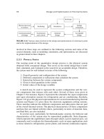
2.2. Station-based design for control system
After considering different stages of a welding process,
this section will describe the functioning of the semiautomatic welding system by dividing the system structure
into stations. According to three different stages of welding
process, three stations may be distinguished (Figure 2).
Station I: Fixing and tack welding;
Station II: Automatic welding by robots;
Station III: Delivering of finished product.
Station I
Fixing & tack
welding
Station II
Automatic welding
by robots
Station III
Delivering finished
product
Figure 2. Station-based design for control system
Station I consist of a Fixed frame and a Shuttle car. The
frame is fixed to the floor. The Shuttle car can move
translationally on Fixed frame from Station I to Station II
and then in reverse direction. Chassis parts are firmly jointed
at Station I. Then they are tack welded before moving to the
station II for the main welding stepperformed by robot. After
44
Giap Quang Huy, Doan Quang Vinh
transferring the chassis from station I to Station II, Shuttle
car will return to its original position at the station I so that
workers can continue to perform a new assembly and tack
weld for a new chassis. Therefore, Shuttle car plays an
important role in coordinating the functioning of the station
I and that of the station II.
Station II consists of a Fixed frame and an Operation car.
The Operation car can move translationally on Fixed frame. It
receives the tack welded chassis frame from the Shuttle car
and carries it to different pre-indicated stop position so that
manipulator robot can perform easily all the welds. Robot’s
stand is fixed on the floor. The Operation car of station II starts
when the Shuttle car already returns to its original position at
the station I. When robots performed all the welds and
finished the main welding step, Operation car continues to
bring the welded chassis to the station III. After delivering the
welded chassis at the station III, Operation car returns to its
original position at station II, where it wait for receiving tack
welded chassis from Shuttle car. The process continues.
2.3. Station II: Synchronous operations between Operation
car and welding robot
Station II is the place where main welding step is
performed automatically to joint cross beams, side beams,
middle straight beams, dump hinges...to straight girder.
The Operation car is designed and fabricated with high
precision. The ability to achieve repeatable accuracy is
± 0.1 mm.
Operation carfunctioning: The moving speed of the
Operation car will be controlled at two levels of speed.
When the Operation car approaches the indicated stop
position, it is slowed down and stopped at right position
with high accuracy level.
Stop positions of Operation car: Stop positions of
Operation car are determined thanks to the side beams of
chassis. In other words, the maximum number of stop
positions is equal to the number of side beams. It means
that the real number of stop positions may be smaller than
that of side beams so that it satisfies: all the welds may be
Horizontal
weld
seam
S1
S2
performed by robots.
Positioning system consists of position detectors and
clamping system. Whenever an approaching side beam is
detected thanks to detectors, clamping system is activated
if this side beam corresponds to a desired stop position. The
clamping system will firmly clamp the side beam to fix the
chassis. Then two manipulator welding robots which are
placed symmetrically on the both sides of the chassis will
start to perform welds. At each stop, robot on each side can
perform many different welds to joint one beam or more
than one beam (or other part) to straight girder. After
finishing all necessary well at each stop the welding torch
will return to its original position. The clamping system
will relax the side beam. Then the Operation car will start
to move to the next stop position. The process continues
until all welds are done.
2.4. Chassis structure
This section broaches welds need to be performed by
welding robot on a real truck chassis. Examples of required
welds on the real chassis number FLD600 is shown in the
Figures 3 and 4, including:
- Vertical seam weld;
- Horizontal seam weld.
There are totally 45 seam welds need to be performed on
a FLD600 chassis as shown in the Table 1. In comparison
with results obtained from [4], weld features have been
considered. Seam welds are taken into account instead of
considering all seam welds as spot welds for simplicity.
z
y
x
I
B
C
Figure 3. The part of chassis number FLD600
Vertical seam weld
S3
S4
S5
x
y
Figure 4. The structure of chassis number FLD600
S6
S7
ISSN 1859-1531 - THE UNIVERSITY OF DANANG, JOURNAL OF SCIENCE AND TECHNOLOGY, NO. 12(85).2014, VOL. 1
3. Optimizing the number of stop positions of
Operation car in the synchronous operation between
robot and Operation car
In this section, linear programming approach is
considered [1], [6]. Since the operating time at the station
I and III depend on operaters, this article focus only on
optimizing the operating time in the syschronous operation
between robot and Operation car at station II [7].
With the assumptions that the spending time for
detecting and clamping a side beam for each stop position
of Operation car is constant and that the mean value of
torch speed to move from a weld to another is constant,
therefore the total time to perform all expected welds on a
chassis depends on the number of stop positions of
Operation car. In this paper, an optimal algorithmis
introduced to:
- Determine the minimum number of stop positions and
corresponding stops so that robot can perform all the welds.
- Determine welds need to be performed respectively at
each stop.
3.1. Linear programing-based problem formulation
a. Variables and parameters
= S1 ,...Si ,...Sn : is the set of possible stop positions
of Operation car. The maximun number of possible stop
positions is equal to the number of side beams. In fact,
Operation car will not stop at each possible stop positions
but only at some of them. It will be computed and preset
thanks to optimization algorithm.
i : is a binary variable which indicates whetherthe
Operation carwill stop ornot at the position Si, i 0;1.
If i 1, the Operation car will stop at the position Si.
Clamping system will be activated to clamp theside
beamcorresponding to the desired stop position Si .
If i 0, the Operation car will not stop at the position Si .
A vector may be defined as the result of aptimization
approach:
…
…
Sn
S1
Si
…
…
n
1
i
P1 ,...Pj ,...Pm is a set of welds need to be performed
(See rubric 3.3).
si p j : is a binary variable which indicates whetherthe
weld Pj will be performed or not when the Operation car
stop at the position Si, .
si p j 1 if the Operation car stops at the positionSi and
robot perform the weld Pj .
si p j 0 if Operation car does not stop at the position Si
/ or it stops at the position Si but robot does not perform the
weld Pj .
A matrix may be defined as the result of aptimization
approach:
…
…
Sn
S1
Si
s1 p1
si p1
sn p1
…
…
P1
…
…
…
…
…
Pj
…
Pm
s p
1
s p
…
…
…
j
…
s p
1 m
i
…
…
…
j
s p
i m
s p
n
45
j
…
s p
n m
d si p j : is the distance from the robot stand center to the
weld Pj when the Operation car stops at the position Si . d si p j
is constant.
A matrix of distance from robot to welds
P P1 ,...Pj ,...Pm
at
different
stop
positions
S = S1 ,...Si ,...Sn of Operation car may be defined.
…
…
Sn
S1
Si
d s1 p1
d si p1
d sn p1
…
…
P1
…
…
…
…
…
…
Pj
d s1 p j
d
d
…
…
si p j
si pn
…
…
…
…
…
…
d sn pm
d s1 pm
d si pm
…
…
Pm
b. Constraints
Constraints on welds:
For verticalwelds and horizontal welds which are located
at lower position: each weld P is performed only once even
though Operation car stops at different positions, thus:
n
1
si p j
(1)
i 1
For horizontal welds located at high position: each weld
P is performed only once either from the right side or from
the left side. It depends on the actual position of the robot
to welds, therefore:
n
i 1
n
si p j / left
si p j / right 1
(2)
i 1
Constraints on the working envelope of robot:
Let Rmax be the maximum radius of the working
envelope of robot. At each stop position Si of Operation
car, the performed weld Pj must locate within the working
envelope of robot arm, therefore:
si p j .dsi p j Rmax
(3)
Constraints on stop positions of Operation car:
When Operation car does not stop at position Si ,i 0,
all variables si p j musts equal to 0. Otherwise it may be 0
or 1 because i 1, therefore:
si p j i
(4)
c. Objective function
As introduced previously, the optimization problem of
welding time is considered as a problem of minimizing the
stop position of Operation car, and it ensures that all welds
will be performed. Optimization problems are considered
may be solved in two steps:
Step 1: Solving the linear programming problems with
objective function which allow to minimum the number of
stops position of Operation car. Objective functionis given by:
Min
n
i 1
i
(5)
Step 2: Let’s note that with the number of stop position
founded in the step 1, suppose it is nmin, some combinations
of nmin stop positions of Operation car may allow satisfying
46
Giap Quang Huy, Doan Quang Vinh
that all welds will be performed. Therefore, in this step 2,
the number nminfounded in Step 1will be assigned as a
constraint. A new objective function allows minimizingthe
total distance from robot tothe performed welds
(corresponding to each stop). It is given by:
Min
n
i 1
i n
n
i 1
(6)
s p .ds p
i
j
From solving step 1, we have the minimum number of
stops is 4. There are 3 cases where the number of stops is
4, which also satisfy the conditions thatall welds may be
performed: {S1S2S4S7}, {S1S3S4S7} and {S1S3S5S7}.
i
j
(7)
3.2. Problem solving
In this paper, solver GLPK is chosen to solve the linear
programing problem.
a. Input data
Input data of the problem include:
The radius of robot working envelope: robot arm used
in this project is the Panasonic TA-1400 with accuracy of
± 0.1 mm. The maximum radius of working envelopeis
Rmax = 1374 mm.
For the reasons of safety and collision avoidance, robot
stand is located at a distance of 884 mm from the symmetry
axis of the chassis.
A real chassis frame prototype is selected to calculate
in this work, it is FLD600, is presented in Figure 4
(designed and provided by Truong Hai Auto Joint Stock
Company). Seven possible stop positions corresponding to
7 side beams of the chassis: S1... S7.
Matrix of d si p j value.
b. Output data
The computed outcome given by solver GLPK includes:
Determine the minimum number of stops and
corresponding stop positions through variables i so that
robot can perform all welds.
Determine the welds need to be performed at each stop
position through variables si p j .
3.3. Result and discussion
After solving the formulated problem by GLPK, some
results are obtained:
• The minimum number of stops is 4; they are P1, P3,
P5, and P7.
• Welds should be performed at each stop position are
shown in table Table 1.
• Total distance from robot to welds calculated by
expression (7) is 43 757 [mm].
Table 1. Welds need to be performed at each stop position
Stop positions Performed welds
S1
PAV1 PAH2R PAV3 PBV1 PBH2L PHV1 PHH2L PHV3
S3
PBV3 PCV1 PCV3 PDV1 PDH2L PIH1 PIV2 PIH3R PIV4 PIH5 PJV1 PJH2L
S5
PCH2R PDV3 PEV1 PEV3 PFV1 PFH2L PGH2L PJV3 PKV1 PKH2R PKV3 PLV1
S7
PEH2RPFV3 PGV1 PGV3 PQV1 PQV2 PLH2R PLV3 PMV1 PMH2R PMV3 PNV1 PNV2
Do not stop at S2, S4, S6
Figure 5. Total distance from the robot to welds in different
cases of fore stop positions of Operation car
Comparison results, as shown in the Figure 5, show
that, among these cases, the total distance from the robot to
welds is smallest in the case of 4 stop {S1S3S5S7}.
4. Conclusion
This paper introduces a design and a solutionfor
optimizing the functioning of a automatic welding system
using robot. First, a station-based design is proposed.
Based on this design, the paper focuseson optimizing the
operating time in the syschronous operation between robot
and Operation car at station II. Thus, it allows increasing
the productivity. In detail, anoptimal algorithmhas been
introduced to determine the minimum number of stop
positions and the correspondingstops so that robot can
perform all the welds. The proposed algorithm also allows
determiningall thewelds need to be performed respectively
at each stop.
REFERENCES
[1] J. Linderoth and T. Ralphs: Noncommercial software for mixedinteger linear programming. Optimization Online, 2005.
[2] M. Fischer: Efficient path planning for cooperating manipulators.
Intelligent Robots and Systems 94. Advanced Robotic Systems and the
Real World, IROS '94. Proceedings of the IEEE/RSJ/GI International
Conference, vol.1, no., pp.673,678 vol.1, 12-16 Sep 1994.
[3] M.S. Erden and B. Maric: Assisting manual welding with robot.
Robotics and Computer-Integrated Manufacturing, Volume 27,
Issue 4, August 2011, Pages 818-828.
[4] Q-H. Giap and Q-V Doan: Áp dụng phương pháp tối ưu tuyến tính
để tối ưu thời gian gia công trong hệ thống tự động hàn khung sàn
xe ben dùng robot. Kỷ yếu Hội nghị toàn quốc lần thứ 2 về Điều
khiển và Tự động hóa VCCA 2013; Vol. 2; pp. 397-404, 2013.
[5] R. Finch: Performance Welding Handbook, Motorbooks, 2005.
[6] Saul I. Gass: Linear Programming: Methods and Applications.
Courier Dover Publications, 2003.
[7] S.F.P. Saramago and V. Steffen Jr: Optimization of the trajectory
planning of robot manipulators taking into account the dynamics of
the system. Mechanism and Machine Theory, Volume 33, Issue 7,
October 1998, Pages 883-894.
The Board of Editors received the paper on 23/10/2014, its review was completed on 28/10/2014)