step motor - Động cơ bước
Bạn đang xem bản rút gọn của tài liệu. Xem và tải ngay bản đầy đủ của tài liệu tại đây (189.83 KB, 6 trang )
1
A stepper motor is an electromechanical
device which converts electrical pulses into
discrete mechanical movements. The shaft
or spindle of a stepper motor rotates in
discrete step increments when electrical
command pulses are applied to it in the
proper sequence. The motors rotation has
several direct relationships to these applied
input pulses. The sequence of the applied
pulses is directly related to the direction of
motor shafts rotation. The speed of the
motor shafts rotation is directly related to
the frequency of the input pulses and the
length of rotation is directly related to the
number of input pulses applied.
Stepper Motor Advantages
and Disadvantages
Advantages
1. The rotation angle of the motor is
proportional to the input pulse.
2. The motor has full torque at stand-
still (if the windings are energized)
3. Precise positioning and repeat-
ability of movement since good
stepper motors have an accuracy of
3 – 5% of a step and this error is
non cumulative from one step to
the next.
4. Excellent response to starting/
stopping/reversing.
5. Very reliable since there are no con-
tact brushes in the motor.
Therefore the life of the motor is
simply dependant on the life of the
bearing.
6. The motors response to digital
input pulses provides open-loop
control, making the motor simpler
and less costly to control.
7. It is possible to achieve very low
speed synchronous rotation with a
load that is directly coupled to the
shaft.
8. A wide range of rotational speeds
can be realized as the speed is
proportional to the frequency of the
input pulses.
Disadvantages
1. Resonances can occur if not
properly controlled.
2. Not easy to operate at extremely
high speeds.
Open Loop Operation
One of the most significant advantages
of a stepper motor is its ability to be
accurately controlled in an open loop
system. Open loop control means no
feedback information about position is
needed. This type of control
eliminates the need for expensive
sensing and feedback devices such as
optical encoders. Your position is
known simply by keeping track of the
input step pulses.
Stepper Motor Types
There are three basic stepper motor
types. They are :
• Variable-reluctance
• Permanent-magnet
• Hybrid
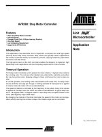
Variable-reluctance (VR)
This type of stepper motor has been
around for a long time. It is probably
the easiest to understand from a
structural point of view. Figure 1
shows a cross section of a typical V.R.
stepper motor. This type of motor
consists of a soft iron multi-toothed
rotor and a wound stator. When the
stator windings are energized with DC
current the poles become magnetized.
Rotation occurs when the rotor teeth
are attracted to the energized stator
poles.
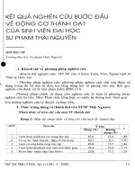
Permanent Magnet (PM)
Often referred to as a “tin can” or
“canstock” motor the permanent
magnet step motor is a low cost and
low resolution type motor with typical
step angles of 7.5° to 15°. (48 – 24
steps/revolution) PM motors as the
Figure 1. Cross-section of a variable-
reluctance (VR) motor.
Industrial Circuits Application Note
Stepper Motor Basics
Figure 2. Principle of a PM or tin-can
stepper motor.
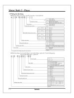
Figure 3. Cross-section of a hybrid stepper
motor.
15°
A
B
C
D
A'
B'
C'
D'
1
6
5
4
3
2
N
S
S
N
N
N
S
N
S
N
NN
S
S
2
name implies have permanent
magnets added to the motor structure.
The rotor no longer has teeth as with
the VR motor. Instead the rotor is
magnetized with alternating north
and south poles situated in a straight
line parallel to the rotor shaft. These
magnetized rotor poles provide an
increased magnetic flux intensity and
because of this the PM motor exhibits
improved torque characteristics when
compared with the VR type.
Hybrid (HB)
The hybrid stepper motor is more
expensive than the PM stepper motor
but provides better performance with
respect to step resolution, torque and
speed. Typical step angles for the HB
stepper motor range from 3.6° to 0.9°
(100 – 400 steps per revolution). The
hybrid stepper motor combines the
best features of both the PM and VR
type stepper motors. The rotor is
multi-toothed like the VR motor and
contains an axially magnetized con-
centric magnet around its shaft. The
teeth on the rotor provide an even
better path which helps guide the
magnetic flux to preferred locations in
the airgap. This further increases the
detent, holding and dynamic torque
characteristics of the motor when com-
pared with both the VR and PM
types.
The two most commonly used types
of stepper motors are the permanent
magnet and the hybrid types. If a
designer is not sure which type will
best fit his applications requirements
he should first evaluate the PM type as
it is normally several times less expen-
sive. If not then the hybrid motor may
be the right choice.
There also excist some special
stepper motor designs. One is the disc
magnet motor. Here the rotor is
designed sa a disc with rare earth
magnets, See fig. 5 . This motor type
has some advantages such as very low
inertia and a optimized magnetic flow
path with no coupling between the
two stator windings. These qualities
are essential in some applications.
Size and Power
In addition to being classified by their
step angle stepper motors are also
classified according to frame sizes
which correspond to the diameter of
the body of the motor. For instance a
size 11 stepper motor has a body di-
ameter of approximately 1.1 inches.
Likewise a size 23 stepper motor has a
body diameter of 2.3 inches (58 mm),
etc. The body length may however,
vary from motor to motor within the
same frame size classification. As a
general rule the available torque out-
put from a motor of a particular frame
size will increase with increased body
length.
Power levels for IC-driven stepper
motors typically range from below a
watt for very small motors up to 10 –
20 watts for larger motors. The maxi-
mum power dissipation level or
thermal limits of the motor are seldom
clearly stated in the motor manu-
facturers data. To determine this we
must apply the relationship P␣ =V ×␣I.
For example, a size 23 step motor may
be rated at 6V and 1A per phase.
Therefore, with two phases energized
the motor has a rated power dissipa-
tion of 12 watts. It is normal practice
to rate a stepper motor at the power
dissipation level where the motor case
rises 65°C above the ambient in still
air. Therefore, if the motor can be
mounted to a heatsink it is often
possible to increase the allowable
power dissipation level. This is
important as the motor is designed to
be and should be used at its maximum
power dissipation ,to be efficient from
a size/output power/cost point of view.
When to Use a Stepper
Motor
A stepper motor can be a good choice
whenever controlled movement is
required. They can be used to advan-
tage in applications where you need to
control rotation angle, speed, position
and synchronism. Because of the in-
herent advantages listed previously,
stepper motors have found their place
in many different applications. Some
of these include printers, plotters,
highend office equipment, hard disk
drives, medical equipment, fax
machines, automotive and many more.
The Rotating Magnetic Field
When a phase winding of a stepper
motor is energized with current a
magnetic flux is developed in the
stator. The direction of this flux is
determined by the “Right Hand
Rule” which states:
“If the coil is grasped in the right
hand with the fingers pointing in the
direction of the current in the winding
(the thumb is extended at a 90° angle
to the fingers), then the thumb will
point in the direction of the magnetic
field.”
Figure 5 shows the magnetic flux
path developed when phase B is ener-
gized with winding current in the
direction shown. The rotor then aligns
itself so that the flux opposition is
minimized. In this case the motor
would rotate clockwise so that its
south pole aligns with the north pole
of the stator B at position 2 and its
north pole aligns with the south pole
of stator B at position 6. To get the
motor to rotate we can now see that
we must provide a sequence of
energizing the stator windings in such
a fashion that provides a rotating
magnetic flux field which the rotor
follows due to magnetic attraction.
Torque Generation
The torque produced by a stepper
motor depends on several factors.
• The step rate
• The drive current in the windings
• The drive design or type
In a stepper motor a torque is devel-
oped when the magnetic fluxes of the
rotor and stator are displaced from
each other. The stator is made up of a
high permeability magnetic material.
The presence of this high permeability
material causes the magnetic flux to
be confined for the most part to the
paths defined by the stator structure
in the same fashion that currents are
confined to the conductors of an elec-
tronic circuit. This serves to concen-
trate the flux at the stator poles. The
Figure 4. Principle of a disc magnet motor
developed by Portescap.
N
N
N
N
S
S
S
3
Figure 5. Magnetic flux path through a
two-pole stepper motor with a lag between
the rotor and stator.
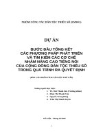
Figure 6. Unipolar and bipolar wound
stepper motors.
torque output produced by the motor
is proportional to the intensity of the
magnetic flux generated when the
winding is energized.
The basic relationship which
defines the intensity of the magnetic
flux is defined by:
H = (N × i) ÷ l where:
N = The number of winding turns
i = current
H = Magnetic field intensity
l = Magnetic flux path length
This relationship shows that the
magnetic flux intensity and conse-
quently the torque is proportional to
the number of winding turns and the
current and inversely proportional to
the length of the magnetic flux path.
From this basic relationship one can
see that the same frame size stepper
motor could have very different torque
output capabilities simply by chang-
ing the winding parameters. More
detailed information on how the
winding parameters affect the output
capability of the motor can be found
in the application note entitled “Drive
Circuit Basics”.
Phases, Poles and Stepping
Angles
Usually stepper motors have two
phases, but three- and five-phase
motors also exist.
A bipolar motor with two phases
has one winding/phase and a unipolar
motor has one winding, with a center
tap per phase. Sometimes the unipolar
stepper motor is referred to as a “four-
phase motor”, even though it only has
two phases.
Motors that have two separate
windings per phase also exist—these
can be driven in either bipolar or
unipolar mode.
A pole can be defined as one of the
regions in a magnetized body where
the magnetic flux density is con-
centrated. Both the rotor and the
stator of a step motor have poles.
Figure 2 contains a simplified picture
of a two-phase stepper motor having 2
poles (or 1 pole pairs) for each phase
on the stator, and 2 poles (one pole
pair) on the rotor. In reality several
more poles are added to both the rotor
and stator structure in order to
increase the number of steps per
revolution of the motor, or in other
words to provide a smaller basic (full
step) stepping angle. The permanent
magnet stepper motor contains an
equal number of rotor and stator pole
pairs. Typically the PM motor has 12
pole pairs. The stator has 12 pole pairs
per phase. The hybrid type stepper
motor has a rotor with teeth. The
rotor is split into two parts, separated
by a permanant magnet—making half
of the teeth south poles and half north
poles.The number of pole pairs is
equal to the number of teeth on one of
the rotor halves. The stator of a hybrid
motor also has teeth to build up a
higher number of equivalent poles
(smaller pole pitch, number of
equivalent poles = 360/teeth pitch)
compared to the main poles, on which
the winding coils are wound. Usually
4 main poles are used for 3.6 hybrids
and 8 for 1.8- and 0.9-degree types.
It is the relationship between the
number of rotor poles and the equival-
ent stator poles, and the number the
number of phases that determines the
full-step angle of a stepper motor.
Step angle=360 ÷ (N
Ph
× Ph)=360/N
N
Ph
= Number of equivalent poles per
phase = number of rotor poles
Ph = Number of phases
N = Total number of poles for all
phases together
If the rotor and stator tooth pitch is
unequal, a more-complicated relation-
ship exists.
Stepping Modes
The following are the most common
drive modes.
• Wave Drive (1 phase on)
• Full Step Drive (2 phases on)
• Half Step Drive (1 & 2 phases on)
• Microstepping (Continuously
varying motor currents)
For the following discussions please
refer to the figure 6.
In Wave Drive only one winding is
energized at any given time. The
stator is energized according to the
sequence A → B →
A
→
B
and the
rotor steps from position 8 → 2 → 4
→ 6. For unipolar and bipolar wound
I
B
Phase A
Phase B
Stator A
Stator B
NS
1
2
3
4
5
6
7
8
N
S
RotorRotor
I
A
I
B
Phase A
Phase B
Stator A
Stator B
1
2
3
4
5
6
7
8
N
S
Phase A
N
S
Phase B
NS
RotorRotor
V
M
V
M
Rotor
I
A
I
B
Phase A
Phase B
Stator A
Stator B
N
NS
S
1
2
3
4
5
6
7
8
N
S
RotorRotor
motors with the same winding param-
eters this excitation mode would result
in the same mechanical position. The
disadvantage of this drive mode is that
in the unipolar wound motor you are
only using 25% and in the bipolar
motor only 50% of the total motor
winding at any given time. This
means that you are not getting the
maximum torque output from the
motor
4
Table 1. Excitation sequences for different drive modes
Figure 7. Torque vs. rotor angular
position.
Figure 8. Torque vs. rotor angle position at
different holding torque.
In Full Step Drive you are ener-
gizing two phases at any given time.
The stator is energized according to
the sequence AB →
A
B →
A
B
→
A
B
and the rotor steps from position
1 → 3 → 5 → 7 . Full step mode
results in the same angular movement
as 1 phase on drive but the mechanical
position is offset by one half of a full
step. The torque output of the
unipolar wound motor is lower than
the bipolar motor (for motors with the
same winding parameters) since the
unipolar motor uses only 50% of the
available winding while the bipolar
motor uses the entire winding.
Half Step Drive combines both
wave and full step (1&2 phases on)
drive modes. Every second step only
one phase is energized and during the
other steps one phase on each stator.
The stator is energized according to
the sequence AB → B →
A
B →
A
→
A
B
→
B
→ A
B
→ A and the
rotor steps from position 1 → 2 → 3
→ 4 → 5 → 6 → 7 → 8. This results
in angular movements that are half of
those in 1- or 2-phases-on drive
modes. Half stepping can reduce a
phenomena referred to as resonance
which can be experienced in 1- or 2-
phases-on drive modes.
The displacement angle is deter-
mined by the following relationship:
X = (Z ÷ 2π) × sin(T
a
÷ T
h
) where:
Z = rotor tooth pitch
T
a
= Load torque
T
h
= Motors rated holding torque
X = Displacement angle.
Therefore if you have a problem
with the step angle error of the loaded
motor at rest you can improve this by
changing the “stiffness” of the motor.
This is done by increasing the holding
torque of the motor. We can see this
effect shown in the figure 5.
Increasing the holding torque for a
constant load causes a shift in the lag
angle from Q
2
to Q
1
.
Step Angle Accuracy
One reason why the stepper motor has
achieved such popularity as a position-
ing device is its accuracy and repeat-
ability. Typically stepper motors will
have a step angle accuracy of 3 – 5%
of one step. This error is also non-
cumulative from step to step. The
accuracy of the stepper motor is
mainly a function of the mechanical
precision of its parts and assembly.
Figure 9 shows a typical plot of the
positional accuracy of a stepper motor.
Step Position Error
The maximum positive or negative
position error caused when the motor
has rotated one step from the previous
holding position.
Step position error = measured step
angle - theoretical angle
Positional Error
The motor is stepped N times from an
initial position (N = 360°/step angle)
and the angle from the initial position
Torque
Angle
T
H
T
a
A
B
C
Stable
Point
Unstable
Point
Stable
Point
Unstable
Region
O
a
O
Torque
Angle
T
Load
T
H1
T
H2
O O
1
2
O
Normal
Wave Drive full step Half-step drive
Phase 1234 1234 12345678
A • ••• ••
B ••••••
A • •• •••
B • •• •••
The excitation sequences for the
above drive modes are summarized in
Table 1.
In Microstepping Drive the
currents in the windings are
continuously varying to be able to
break up one full step into many
smaller discrete steps. More
information on microstepping can be
found in the microstepping chapter.
Torque vs, Angle
Characteristics
The torque vs angle characteristics of
a stepper motor are the relationship
between the displacement of the rotor
and the torque which applied to the
rotor shaft when the stepper motor is
energized at its rated voltage. An ideal
stepper motor has a sinusoidal torque
vs displacement characteristic as
shown in figure 8.
Positions A and C represent stable
equilibrium points when no external
force or load is applied to the rotor
shaft. When you apply an external
force T
a
to the motor shaft you in
essence create an angular
displacement, Θ
a
. This angular
displacement, Θ
a
, is referred to as a
lead or lag angle depending on wether
the motor is actively accelerating or
decelerating. When the rotor stops
with an applied load it will come to
rest at the position defined by this
displacement angle. The motor
develops a torque, T
a
, in opposition to
the applied external force in order to
balance the load. As the load is
increased the displacement angle also
increases until it reaches the
maximum holding torque, T
h
, of the
motor. Once T
h
is exceeded the motor
enters an unstable region. In this
region a torque is the opposite
direction is created and the rotor
jumps over the unstable point to the
next stable point.
5
Figure 9. Positional accuracy of a stepper
motor.
Figure 10. Torque vs. speed characteristics
of a stepper motor.
is measured at each step position. If
the angle from the initial position to
the N-step position is Θ
N
and the
error is ∆Θ
N
where:
∆Θ
N
= ∆Θ
N
- (step angle) × N.
The positional error is the difference
of the maximum and minimum but is
usually expressed with a ± sign. That
is:
positional error = ±
1
⁄2(∆Θ
Max
- ∆Θ
Min
)
Hysteresis Positional Error
The values obtained from the measure-
ment of positional errors in both
directions.
Mechanical Parameters,
Load, Friction, Inertia
The performance of a stepper motor
system (driver and motor) is also
highly dependent on the mechanical
parameters of the load. The load is
defined as what the motor drives. It is
typically frictional, inertial or a
combination of the two.
Friction is the resistance to motion
due to the unevenness of surfaces
which rub together. Friction is
constant with velocity. A minimum
torque level is required throughout
the step in over to overcome this
friction ( at least equal to the friction).
Increasing a frictional load lowers the
top speed, lowers the acceleration and
increases the positional error. The
converse is true if the frictional load is
lowered
Inertia is the resistance to changes
in speed. A high inertial load requires
a high inertial starting torque and the
same would apply for braking. In-
creasing an inertial load will increase
speed stability, increase the amount of
time it takes to reach a desired speed
and decrease the maximum self start
pulse rate. The converse is again true
if the inertia is decreased.
The rotor oscillations of a stepper
motor will vary with the amount of
friction and inertia load. Because of
this relationship unwanted rotor oscil-
lations can be reduced by mechanical
damping means however it is more
often simpler to reduce these
unwanted oscillations by electrical
damping methods such as switch from
full step drive to half step drive.
Torque vs, Speed
Characteristics
The torque vs speed characteristics are
the key to selecting the right motor
and drive method for a specific
application. These characteristics are
dependent upon (change with) the
motor, excitation mode and type of
driver or drive method. A typical
“speed – torque curve” is shown in
figure9.
To get a better understanding of
this curve it is useful to define the
different aspect of this curve.
Holding torque
The maximum torque produced by
the motor at standstill.
Pull-In Curve
The pull-in curve defines a area refered
to as the start stop region. This is the
maximum frequency at which the
motor can start/stop instantaneously,
with a load applied, without loss of
synchronism.
Maximum Start Rate
The maximum starting step frequency
with no load applied.
Pull-Out Curve
The pull-out curve defines an area
refered to as the slew region. It defines
the maximum frequency at which the
motor can operate without losing syn-
chronism. Since this region is outside
the pull-in area the motor must
ramped (accelerated or decelerated)
into this region.
Maximum Slew Rate
The maximum operating frequency of
the motor with no load applied.
The pull-in characteristics vary also
depending on the load. The larger the
load inertia the smaller the pull-in
area. We can see from the shape of the
curve that the step rate affects the
torque output capability of stepper
motor The decreasing torque output as
the speed increases is caused by the
fact that at high speeds the inductance
of the motor is the dominant circuit
element.
Angle
Deviation
Theoretical
Position
Positional
Accuracy
Hysteresis
Error
Torque
Speed
P.P.S.
Start-Stop Region
Pull-in
Torque
curve
Slew
Region
Holding Torque
Pull-out
Torque
Curve
Max Start Rate
Max Slew Rate
The shape of the speed - torque
curve can change quite dramatically
depending on the type of driver used.
The bipolar chopper type drivers
which Ericsson Components produces
will maximum the speed - torque
performance from a given motor. Most
motor manufacturers provide these
speed - torque curves for their motors.
It is important to understand what
driver type or drive method the motor
manufacturer used in developing their
curves as the torque vs. speed charac-
teristics of an given motor can vary
significantly depending on the drive
method used.
6
Stepper motors can often exhibit a
phenomena refered to as resonance at
certain step rates. This can be seen as a
sudden loss or drop in torque at cer-
tain speeds which can result in missed
steps or loss of synchronism. It occurs
when the input step pulse rate coin-
cides with the natural oscillation
frequency of the rotor. Often there is a
resonance area around the 100 – 200
pps region and also one in the high
step pulse rate region. The resonance
phenomena of a stepper motor comes
from its basic construction and there-
fore it is not possible to eliminate it
completely. It is also dependent upon
the load conditions. It can be reduced
by driving the motor in half or micro-
stepping modes.
Figure 11. Single step response vs. time.
Single Step Response and
Resonances
The single-step response character-
istics of a stepper motor is shown in
figure 11.
When one step pulse is applied to a
stepper motor the rotor behaves in a
manner as defined by the above curve.
The step time t is the time it takes the
motor shaft to rotate one step angle
once the first step pulse is applied.
This step time is highly dependent on
the ratio of torque to inertia (load) as
well as the type of driver used.
Since the torque is a function of the
displacement it follows that the accel-
eration will also be. Therefore, when
moving in large step increments a
high torque is developed and
consequently a high acceleration. This
can cause overshots and ringing as
shown. The settling time T is the time
it takes these oscillations or ringing to
cease. In certain applications this
phenomena can be undesirable. It is
possible to reduce or eliminate this
behaviour by microstepping the
stepper motor. For more information
on microstepping please consult the
microstepping note.
Angle
tT
Time
O

![[Khóa luận]thiết kế điều khiển động cơ môtơ bước](https://media.store123doc.com/images/document/13/ce/vx/medium_vxg1387631486.jpg)