Experimental study on the wave dissipation performance of a perforated semi-circular floating breakwater
Bạn đang xem bản rút gọn của tài liệu. Xem và tải ngay bản đầy đủ của tài liệu tại đây (4.02 MB, 12 trang )
Journal of Science and Technology in Civil Engineering, HUCE (NUCE), 2022, 16 (3): 59–70
EXPERIMENTAL STUDY ON THE WAVE DISSIPATION
PERFORMANCE OF A PERFORATED SEMI-CIRCULAR
FLOATING BREAKWATER
Vu Minh Tuana , Bach Duonga,∗, Vu Quoc Hunga , Nguyen Duc Manha , Nguyen Manh Linhb
a
Faculty of Hydraulic Engineering, Hanoi University of Civil Engineering,
55 Giai Phong road, Hai Ba Trung district, Hanoi, Vietnam
b
Key Laboratory of River and Coastal Engineering, Vietnam Academy for Water Resources,
Dong Da district, Hanoi, Vietnam
Article history:
Received 12/5/2022, Revised 31/5/2022, Accepted 03/6/2022
Abstract
A new type of floating breakwater (FB) is proposed in this paper. Its hydrodynamic performance has been
tested. The structure of the new breakwater named perforated semi-circular floating breakwater (SCFB) consists
of two parts: a main body of a box-shaped base block and a semi-circular upper structure is perforated for the
purpose of absorbing breaking and overtopping wave energy. A series of experiments were carried out on
the new floating breakwater and traditional box floating breakwater to compare their performances. A twodimensional wave flume was used in the experiment; the incident, transmitted, and reflected waves from the
floating breakwaters were measured. Results showed that the new floating breakwater had a better performance
than the traditional box floating breakwater: wave transmission was significantly reduced by the semi-circular
upper part, especially for high waves.
Keywords: perforated semi-circular floating breakwater; experimental study; wave transmission; wave reflection; energy dissipation.
/>
© 2022 Hanoi University of Civil Engineering (HUCE)
1. Introduction
Located in the tropical monsoon belt, Vietnam is often directly affected by tropical depressions
and storms. With a coastline of more than 3,260km long with a very large number of vessels, especially small ships (fishing boats and cruise ships), the construction of mooring areas to avoid the impact of high waves and storms is always necessary and effective to minimize the damage to people and
properties. In addition, Vietnam is considered as one of the countries most heavily affected by climate
change [1]. Consequences of climate change have caused sea level rise and extreme weather events,
which results in increase in wave height, the number of sea storms, cyclones, as well as shoreline and
bottom erosion rate, etc. In order to protect harbor basin and boat mooring areas, more structures of
breakwaters, wave dampers, etc. will be required to build higher, larger and heavier. However, most of
the coastal plains of Vietnam are located on weak and very weak soils, especially the Mekong River
Delta with a layer of clay mud with thickness ranging from 10 to 50 m [2]. The construction of protection works on such weak soils will be complicated, expensive and risky. Therefore, it is necessary to
∗
Corresponding author. E-mail address: (Duong, B.)
59
Tuan, V. M., et al. / Journal of Science and Technology in Civil Engineering
study new structural solutions that are not only suitable for wave reduction but also suitable for weak
soils as well as sea level rise scenarios due to the climate change for ports and mooring areas, located
in the delta region of Vietnam.
In addition, the increase in maritime traffic along with the vessel sizes require deeper water
berthing facilities at ports to facilitate the loading and unloading of cargo [3]. As a result, breakwaters can provide suitable calm conditions for the mooring of ships in their rear and at the same time
ensure minimal wave reflection from the seaside. Conventional rubble mound breakwater structures
would not be economical for such deep waters. Tutuarima and d’Angremond [4] made a cost comparison of different breakwaters for hypothetical cases with the same site conditions and concluded that
the rubble mound breakwaters are very favorable in water depth up to 8m. Caisson and mixed-type
breakwaters are preferred at water depths of 8 - 20 m and 20 - 30 m, respectively. However, impermeable breakwater structures impede the free movement of sediments, thereby causing shoreline erosion
problems downstream, especially in areas where the longshore drift is significant. Therefore, an ideal
breakwater in deeper waters would be one that would both allows the free passage of sediments, facilitates the exchange of water between in and out of the port, and at the same time dissipates wave
energy.
In order to solve the problem of allowing sediment and water to exchange freely while still ensuring efficient dissipation of wave energy and suitable for weak soils, some researchers have proposed
the use of FBs or submerged breakwaters as an appropriate solution [5–7]. Submerged breakwaters
have been widely used in recent years. One of their most prominent advantages is that they can provide
the desired protection without destroying or detracting from the aesthetic and recreational functions
of the coastal area [8]. In addition, it provides a water circulation, minimizing the possibility of sediment deposition behind the structure and minimizing backflow erosion by allowing flows to pass over
the top and middle of the breakwater and shoreline. However, this structure still has some limitations,
such as, the efficiency of wave attenuation will be low in the condition of sea level rise, and most of
this type of submerged breakwater is by gravity structure with large volume, not suitable for the weak
soils. FBs become more appropriate in such cases. In addition to their ability to dissipate wave energy
and their ability to adapt to water level fluctuations, they have other advantages such as being suitable
for soft soils, allowing sediment to move through freely and less impact on the ocean floor. It is generally agreed that FBs perform well under normal conditions [9–14], but their stability and efficiency
in extreme sea conditions remains questionable. Although many scientists have devoted themselves to
increasing the performance of FBs, research development is still very limited. There is still a big gap
between current technology and demand. This paper introduces a new modified type of FB. Series of
two-dimensional wave flume experiments were carried out to investigate the wave attenuation of the
new modified type of FB. Research on the physical model of FBs focuses on the wave transmission,
wave reflection and wave energy dissipation under random wave conditions. Comparative tests were
also carried out between the new modified type of FB and the traditional box FB.
2. Physical model tests
2.1. Model design of FB
Based on the research results of Dhinakaran [15] and Teh et al. [10] on the fixed perforated
semicircular breakwater, the authors have improved and proposed a new modified floating breakwater
model – the perforated semicircular floating breakwater to overcome some limitations of traditional
breakwaters such as unsuitable for weak soils, efficiency decreases with sea level rise, impede the
60
Tuan, V. M., et al. / Journal of Science and Technology in Civil Engineering
circulation of water and sediment as well as such as affecting the habitat of marine species and poor
mobility. This new modified floating breakwater model consists of a box base that provides buoyancy
for the structure and a perforated semicircular arch that provides damping of overtopping waves. The
dimensions of this FB model is selected and optimized according to the formulas of Jones [16], Briggs
[17] và Wagner [18].
To investigate the wave dissipation of the new FB, two models of FB were designed according
to the similarity theory and with approximately equal weight of fabricated reinforced concrete. According to the dimensions of the experimental facilities and the experimental wave conditions, the
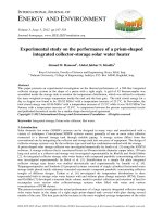
geometrical similarity scale for the model is 1 : 20. Model 1 (TFB-1) is a traditional box-shaped FB
with a length of 1,000 mm, a width of 600 mm, a height of 300 mm and a draught of 155 mm (Fig. 1).
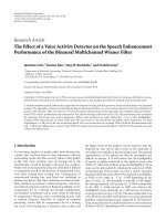
Meanwhile, model 2 (TFB-2) is a perforated semi-circular FB (Fig. 2). The structure of TFB2 consists
of two parts. The base is a reinforced concrete block with a length of 1,000 mm, a width of 600 mm,
a height of 250 mm and a draught of 155 mm. The upper part is a semi-circular dome with a radius
of 125 mm, a thickness of 12.5 mm and perforated with a porosity of 10% according to the research
results of Dhinakaran [15] and Thanh [19]. These FBs are anchored by a system of four mooring
chains with a length of 1.4 m. The main parameters of the two models are listed in Table 1. In this
Figure 1. The TFB-1 floating breakwater: test model (Unit: mm)
Figure 2. The TFB-2 floating breakwater: test model (Unit: mm)
61
Tuan, V. M., et al. / Journal of Science and Technology in Civil Engineering
study, the influence of the mooring system on the response of the FBs as well as the chain tension
force was not taken into consideration.
Table 1. Main parameters of experimental models
TFB-1
Parameters
Length, L (mm)
Width, B (mm)
Height, H (mm)
Draught, T (mm)
Freeboard, h (mm)
Semicircular radius, R (mm)
Hole diameter, a (mm)
Mass, M (kg)
TFB-2
Prototype
Model
Prototype
Model
20,000
12,000
6,000
3,100
2,900
1,000
600
300
155
145
764,063
95.5
20,000
12,000
5,000
3,100
1,900
2,500
450
764,063
1,000
600
250
155
95
125
22.5
95.5
2.2. Equipment and instruments
Experimental scenarios were carried out on the wave flume with a total length of 34 m, of which
effective length is 25 m, width of 1 m, height of 1 m at the National Key Laboratory of River and
Coastal Engineering, Vietnam Academy for Water Resources. The wave flume consists of 2 parts, the
concrete part is the part for the wave generator with a length of 9 m, usually used to generate the deep
water waves where the water depth is large; the remaining part has a length of 25 m was made of 8 mm
glass, this part was used to arrange the physical model to easily observe the phenomena of interaction
between waves and the structure. The maximum water depth in the flume is 70 cm; however the depth
in this study is only 60 cm. The plunger wave generator can generate a maximum wave height of 25
cm, period up to 5.0 seconds.
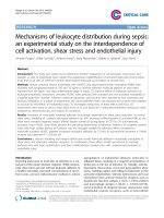
Six conductance type wave gauges (W1, W2, W3, W4, W5 and W6) were used to record the water
surface elevation at different locations in the flume. All six wave gauges are calibrated and verified
by wet test method before measuring the study scenarios. Gauge W1 placed in front of the floating
breakwater at a distance of 4 times the longest wave length generated in the flume to measure the
incident wave height before being affected by the structure. Three wave gauges (W2, W3 and W4)
located in front of the model were used to separate the incident and reflected waves using the method
of Mansard and Funke [20]. The gauge W4 was located at a minimum distance of half of the longest
wave length generated in the flume. The separation distances between the three probes were altered
Figure 3. Details of flume and position of model and wave gauges (Unit: mm)
62
Tuan, V. M., et al. / Journal of Science and Technology in Civil Engineering
for each wave peak period. The gauge W5 located at a distance of 50 mm from the seaward wall of
the model was used to measure the surface elevation just in front of the model. The transmitted waves
were measured by the gauge W6, which was located at a distance 2.5 m from the leeward wall of the
model. The details of the flume and positions of the wave gauges and the test model are shown in
Fig. 3.
2.3. Testing conditions
The perforated semi-circular floating breakwater model was tested in random sea conditions since
the nature of open sea is in random processes. The irregularity of the wave pattern was generated by
JONSWAP spectrum. The water depth during the model tests is 0.6 m. The experiments were organized into two different sets, according to the configuration of the floating breakwater. Two different
floating breakwater configurations with the same material weight were investigated: traditional box
floating breakwater (TFB-1) and perforated semi-circular floating breakwater (TFB-2). Considering
the wave environmental parameters in Vietnam East Sea [21, 22] as well as referring to physical modeling experiments on the interaction between wave and breakwater [5, 9, 10, 13, 23–29], in every
set, 5 monsoon wave conditions with the experimental wave periods ranging from 1.1 to 1.7 s, and
the experimental wave heights from 0.05 to 0.15 m. Approximately 1,000 waves are taken for each
experiment to ensure that the fundamental frequency range (periods) of the wave spectrum is fully
generated. Details of wave parameters in this experimental study are listed in Table 2.
Table 2. Experimental test conditions
Case (∗ )
H50_T11
H75_T13
H100_T14
H125_T16
H150_T17
Wave height, H s
Wave period, T p
Wave length, L s
Prototype (m) Model (cm) Prototype (s) Model (s) Prototype (m) Model (m)
1.0
1.5
2.0
2.5
3.0
5.0
7.5
10.0
12.5
15.0
4.92
5.81
6.26
7.16
7.60
1.1
1.3
1.4
1.6
1.7
36.6
48.3
54.1
65.5
71.0
1.83
2.42
2.71
3.28
3.55
(∗ ): Ha _T b , where: Ha – experimental wave height (cm); T b – experimental wave period (s)
2.4. Performance evaluation criteria
The efficiency of FBs is measured by transmission coefficient (Kt ), reflection coefficient (Kr ) and
energy dissipation coefficient (Kd ). The wave transmission coefficient, Kt , is determined according
to Hales [30] as follows:
Ht
(1)
Kt =
Hi
where Ht is the transmitted wave height and Hi is the incident wave height.
Under ideal conditions, reflection coefficient of the FB is calculated as follows:
Kr =
where Hr is the reflected wave height.
63
Hr
Hi
(2)
Tuan, V. M., et al. / Journal of Science and Technology in Civil Engineering
The wave energy dissipation is calculated through the dissipation coefficient Kd determined according to Teh et al. [31] based on the law of conservation of energy as follows:
Kd =
Ed
=
Ei
1 − Kr2 − Kt2 =
1−
Hr
Hi
2
−
Ht
Hi
2
(3)
where Ei is incident wave energy and Ed is energy loss at the floating breakwater.
Many research results [10, 23, 24, 26, 27, 29, 32, 33] show that the main factors affecting the
wave transmission, wave reflection and wave energy dissipation including the form of structure, the
relative width of FB (the ratio of width and incident wave length, B/L) and wave steepness (the ratio of
incident wave height and length, H/L). Therefore, this paper will focus on analyzing the relationship
between the coefficients and these main factors for two FB models.
3. Results and discussions
3.1. Wave transmission coefficient
The hydraulic behavior of the SCFB in random waves was investigated in relation to the structural
geometry and wave conditions. In this study, the influence of wave conditions on the behavior of the
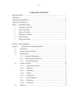
FB is expressed as the wave steepness. Fig. 4 shows the variation of wave transmission coefficient
of the two FB models according to the wave steepness. The results show that the Kt of each model
increases as the wave gets steeper. For FB models, a larger wave length means a greater motion
response and a greater amount of energy transmitted through the breakwater. By comparing the two
models, it is found that the wave attenuation performance of TFB-2 is always better for different
wave steepness. When the wave height is 0.05 m and the wave period is 1.1 s, the wave transmission
coefficient Kt of the TFB-2 model is 4.9% smaller than that of the TFB-1 model. For wave heights
of 0.075 m and 0.1 m, respectively, with wave periods of 1.3 s and 1.4 s, the difference in wave
transmission coefficient Kt between the two models is not significant. However, the TFB-2 model
becomes more efficient at attenuating the waves than the TFB-1 model with increasing wavelength,
especially when the wave height exceeds 0.125 m (1/2 of the model height or diameter of perforated
Figure 4. The relationship between wave steepness (H/L) and transmission coefficient (Kt )
64
Tuan, V. M., et al. / Journal of Science and Technology in Civil Engineering
semicircular dome) corresponds to a wave period of 1.6 s. When the wave height is 0.125 m, the Kt of
TFB-2 model is 7.6% smaller than that of TFB-1 model. When the wave height is up to 0.15 m and the
wave period is 1.7 s, the Kt of the TFB-2 model is 6.2% smaller than that of the TFB-1 model. These
results suggest that the greater the wave height, the more effective the perforated semi-circular FB is in
wave attenuation compared with the traditional box-shaped FB. Moreover, Fig. 4 also reveals that the
floating breakwater T-FB-2 achieves good wave reduction when the wave steepness of H/L ≤ 0.038
as suggested by Briggs [17].
In addition to the influence of wave conditions, the role of the structural geometry on the wave
attenuation of the FB was also considered in this study. The geometrical feature is expressed as the
relative width, B/L, where B is the width of the FB and L is the incident wave length. Fig. 5 shows
the effect of B/L on the wave transmission coefficient Kt for FB samples TFB-1 and TFB-2. It is
clear from Fig. 5 that Kt decreases with increasing of B/L. This revealed that the wave attenuation
of the SCFB improved with a decreasing wave period and an increased FB width. This result is also
similar to the results of Zhan et al. [34], Damdam [35] and Masoudi [36]. This could be because,
for a given wavelength, as the B/L increases, the width of the breakwater increases and there is a
series of obstructions as the waves pass through the breakwater. This creates turbulences with eddies
and dissipation of wave energy, and a significant interaction between the structure and the wave takes
place resulting in larger wave attenuation. As shown in Fig. 5, if the wave transmission coefficient
Kt is less than 0.5 then the B/L should be greater than 0.18 for the TFB-2 model and larger than 0.2
for the TFB-1 model. In addition, it is easily seen that the TFB-2 model has better wave attenuation
than the TFB-1 model. Specifically, most of the wave transmission coefficients of TFB-2 model are
smaller than those of TFB-1 model at the same B/L value. When the relative width is between 0.21
and 0.25, the two FB models have similar wave damping effect. Fig. 5 also shows that the floating
breakwater models of T-FB-1 and T-FB-2 are considered to have good wave damping performance as
required by the harbor and mooring areas [17] when the relative width B/L is greater than 0.18 and
0.2, respectively.
Figure 5. The relationship between relative width (B/L) and transmission coefficient (Kt )
3.2. Wave reflection coefficient
The effect of H/L wave steepness on the wave reflection coefficients Kr is shown in Fig. 6. In
general, the graphs of the wave reflection coefficient Kr of both FBs tend to decrease gradually with
65
Tuan, V. M., et al. / Journal of Science and Technology in Civil Engineering
the increase of the wave steepness. This shows that when the wave period is larger (long waves),
the energy of the waves passing through the breakwater structure will be greater and the energy of
the waves reflected from the FB will decrease. In addition, the influence of structural geometry on
Kr seems to prevail in this case. It is easily seen that the TFB-2 model produces a larger reflection
coefficient than the TFB-1 model at the same wave steepness value. In the range of 0.028 ≤ H/L ≤
0.038, the wave reflection coefficients of the TFB-2 model are always 1% to 13% larger than those
of the TFB-1 model. In case of H/L > 0.038, the difference in the incident wave reflection ability of
the two models is very small. Therefore, the floating breakwater TFB-2 can be considered as a better
reflective structure than the model TFB-1.
Figure 6. The relationship between wave steepness (H/L) and reflection coefficient (Kr )
Figure 7. The relationship between relative width (B/L) and reflection coefficient (Kr )
Fig. 7 shows the wave reflection characteristics of the TFB-1 and TFB-2 breakwater models for
the relative width of B/L. The dependence of Kr on B/L is believed to be significantly less than that
of Kt . The Kr data points of both models show that the wave reflectivity decreases as the wave period
increases. The Kr of the TFB-1 model seems to peak first at B/L ≈ 0.18, and then slightly decrease at
0.18 < B/L ≤ 0.25 before increasing again at 0.25 < B/L ≤ 0.33. This same trend was also observed
66
Tuan, V. M., et al. / Journal of Science and Technology in Civil Engineering
in the free surface perforated semicircular FB tested in random waves [6]. However, the Kr of the
TFB-2 model was found that the Kr coefficient increased continuously when 0.16 ≤ B/L ≤ 0.25.
The value of Kr of TFB-2 model starts to decrease in relative width B/L > 0.25. This decrease in the
higher B/L band can be attributed to (i) the presence of overtopping waves which limits the amount of
reflected wave energy; and (ii) significant energy loss due to excessive wave and structure interaction
in the TFB-2 model.
3.3. Wave energy dissipation coefficient
The amount of energy dissipated at the breakwater is quantified by the coefficient Kd , which is
equivalent to Ed /Ei as shown in Eq. (3). Some of the mechanisms that lead to the energy loss observed
during testing include breaking waves, run-up and run-down waves, eddy formation underneath the
experimental models, and sound and heat generation. Fig. 8 presents the variation of Kd coefficient of
two models of TFB-1 and TFB-2 corresponding to the change of H/L wave steepness. The decreasing
trend of Kd with both FB models as the H/L wave steepness increases (increasing the wave period) as
shown in the figure shows that shorter waves tend to dissipate more energy at the breakwater. When
0.028 ≤ H/L ≤ 0.037 corresponds to 1.1 s ≤ T p ≤ 1.4 s, the TFB-1 dissipates energy more efficiently
than the TFB-2 from 4% to 7%. However, when T p > 1.4 s, TFB-2 model exhibits the wave energy
dissipation better than TFB-1 model from 2% to 5%. In general, both models of FB can be considered
to have good wave energy dissipation capacity as it is capable of dissipating 60–80% of incident wave
energy.
Figure 8. The relationship between wave steepness (H/L) and dissipation coefficient (Kd )
Fig. 9 shows the effect of the relative width B/L on the energy dissipation coefficient Kd of the
two tested models of TFB-1 and TFB-2. Both FB samples exhibit high efficiency in dissipating wave
energy of short period waves. The larger the relative width of the breakwater, the larger the Kd . At
0.16 < B/L < 0.2, the wave damping coefficient Kd of the TFB-2 model is larger than that of the
TFB-1 model. For 0.2 < B/L < 0.32, the TFB-1 model proved to be more efficient in dissipating
wave energy. However, when B/L > 0.25, the TFB-1 model has almost no improvement in wave
energy dissipation despite the increase of relative length B/L. The energy dissipation of the model
TFB-1 in this B/L range can only be further enhanced by increasing the draft of the breakwater.
Meanwhile, the TFB-2 breakwater sample exhibits a remarkable increase of the Kd wave energy
dissipation coefficient.
67
Tuan, V. M., et al. / Journal of Science and Technology in Civil Engineering
Figure 9. The relationship between relative width (B/L) and dissipation coefficient (Kd )
3.4. Summary of hydrodynamic coefficients
The wave transmission coefficient Kt , reflection coefficient Kr and energy dissipation coefficient
Kd of both breakwater models are summarized in Table 3. It is easily seen that the T-FB-2 model
produces a smaller wave transmission coefficient than that of T-FB-1 model. That means that the
transmission wave height in the water area behind the T-FB-2 model is smaller than that of the T-FB1 case. However, the wave reflection coefficient of the T-FB-2 sample is larger than that of T-FB-1
sample. For wave energy dissipation capacity, the perforated semi-circular FB has better wave energy
dissipation capacity than that of traditional box FB when the wave peak period is greater than 1.4 s.
Table 3. Summary of Kt , Kr and Kd values of FB
Coefficients
T-FB-1
T-FB-2
Kt
Kr
Kd
0.36–0.59
0.47–0.54
0.66–0.76
0.34–0.55
0.49–0.56
0.74–0.77
4. Conclusions
In this paper, the authors proposed a new model of FB. Several experiments have been carried out
to evaluate the performance characteristics of the traditional box-shaped FB and this new type with the
same mass of material in random waves. The ranges of wave transmission coefficient Kt , reflection
coefficient Kr and energy dissipation coefficient Kd of both breakwater models are estimated under
the different wave conditions. Wave transmission and wave energy dissipation capacity of the FB
is controlled by both the wave steepness, H/L and the relative width, B/L. Meanwhile, the wave
reflection coefficient strongly depends only on the wave steepness H/L. The results of experimental
studies demonstrate that the use of the upper perforated semi-circular arch can significantly improve
the performance of the breakwater. However, ways to reduce mooring line force tension and motion
responses of new type of FB need to be investigated further.
68
Tuan, V. M., et al. / Journal of Science and Technology in Civil Engineering
Acknowledgement
This paper is part of the “Study and evaluation of wave dissipation of floating breakwater structure
“T-FB” applied in construction of port and ship anchorage protection works” research project (Grant
no. DT214006) at the Port and Waterways Department of Hanoi University of Civil Engineering,
funded by the Ministry of Transport (Vietnam).
References
[1] IPCC (2007). Climate change 2007: Impacts, adaption and vulnerability: contribution of working group ii
to the fourth assessment report of the intergovernmental panel on climate change. Climate Change 2007,
Cambridge University Press.
[2] Giao, P. H., Dung, N. T., Long, P. V. (2008). An integrated geotechnical–geophysical investigation of
soft clay at a coastal site in the Mekong Delta for oil and gas infrastructure development. Canadian
Geotechnical Journal, 45(11):1514–1524.
[3] Ramnarayan, S. K., Sannasiraj, S. A., Sundar, V. (2019). Hydrodynamic performance of pile supported
breakwaters—A review. In APAC 2019, Springer Singapore, 929–935.
[4] Tutuarima, W. H., d’Angremond, K. (1999). Cost comparison of breakwater types. In Coastal Engineering, American Society of Civil Engineers, 1934–1944.
[5] Kamath, A., Sasikumar, A., Bihs, H. (2018). Numerical study of wave interaction with a submerged
porous breakwater in combination with a floating breakwater. Coastal Engineering Proceedings, (36):
38.
[6] Trung, L. H., Tuan, N. V., Tung, T. T., Linh, D. T., Duy, N. T., Duong, B. (2021). Experimental assessment
of wave reduction possibility of porous concrete blocks. Journal of Science and Technology in Civil
Engineering (STCE) - HUCE, 15(3V):44–54. (in Vietnamese).
[7] Vu, M. T., Nguyen, V. T., Nguyen, T. V. (2019). Predicting the effect of submerged breakwaters on
hydrodynamics and sediment transport-case study of Ba Lang beach (Nha Trang, Vietnam). In APAC
2019, Springer Singapore, 921–928.
[8] Ranasinghe, R., Turner, I. L. (2006). Shoreline response to submerged structures: A review. Coastal
Engineering, 53(1):65–79.
[9] Cho, I.-H. (2016). Transmission coefficients of a floating rectangular breakwater with porous side plates.
International Journal of Naval Architecture and Ocean Engineering, 8(1):53–65.
[10] Ji, C.-Y., Chen, X., Cui, J., Gaidai, O., Incecik, A. (2016). Experimental study on configuration optimization of floating breakwaters. Ocean Engineering, 117:302–310.
[11] Sao, H. H., Dung, N. V. (2011). The physical model of floating breakwater deal with the efficient decrease
of wave level to protect marinas and small harbours. Journal of Water Resources and Environmental
Engineering.
[12] Teh, H. M., Azizan, M. S. M., Kurian, V. J., Hashim, A. M. (2015). Use of a floating breakwater system
as an environmentally friendly method of coastal shelter. In WIT Transactions on The Built Environment,
WIT Press.
[13] Teh, H. M., Venugopal, V., Bruce, T. (2011). Hydrodynamic performance of a free surface semicircular
perforated breakwater. Coastal Engineering Proceedings, 1(32):20.
[14] Trung, N. T. (2018). Assessment of wave reduction effect of anchored pier type floating structure for berth.
Journal of Science and Technology in Civil Engineering (STCE) - HUCE, 12(7):66–73. (in Vietnamese).
[15] Dhinakaran, G. (2010). Hydrodynamic characteristics of semi-circular breakwaters: Review article. Asian
Journal of Applied Sciences, 4(1):1–21.
[16] Jones, D. B. (1971). Transportable breakwaters–A survey of concepts. Technical report, Naval Civil
Engineering Laboratory.
[17] Briggs, M. J. (2001). Performance characteristics of a rapidly installed breakwater system. Technical
report, U.S. Army Engineer Research and Development Center: Vickburg, MS.
69
Tuan, V. M., et al. / Journal of Science and Technology in Civil Engineering
[18] Wagner, H., Gotz, A., Reinsch, R., Kaiser, H. J. (2022). Schwimmende wellenbrecher im einsatz in einem
tagenbaurestsee mitteldeutschlands. Binnenschifffahrt ZfB.
[19] Thanh, N. V. (2014). A semi-circular breakwater is an economic solution for coastal estuarine structures.
Journal of Transport, 11:31–34. (in Vietnamese).
[20] Mansard, E. P. D., Funke, E. R. (1980). He measurement of incident and reflected spectra using a least
squares method. Coastal Engineering, 1(17):154–172.
[21] Dat, L. D., Toan, D. V., Van, N. C., Hoa, D. T. (2017). Ocean wave energy in the world and proposed
research and development for Vietnamese sea areas. Journal of Climate Change Science, 2.
[22] Hoan, N. T., Ly, N. T. H., Dung, N. M. (2017). Evaluation of the wave energy potential in the coastal
area of Vietnam according to the NOAA’s long wave data. Journal of Science and Technology in Civil
Engineering (STCE) - HUCE, 32.
[23] Koutandos, E., Prinos, P., Gironella, X. (2005). Floating breakwaters under regular and irregular wave
forcing: reflection and transmission characteristics. Journal of Hydraulic Research, 43(2):174–188.
[24] Pe˜na, E., Ferreras, J., Sanchez-Tembleque, F. (2011). Experimental study on wave transmission coefficient, mooring lines and module connector forces with different designs of floating breakwaters. Ocean
Engineering, 38(10):1150–1160.
[25] Thanh, N. V. (2014). Wave pressure is exerted on the semi-circular breakwater. Journal of Transport, 12:
24–28. (in Vietnamese).
[26] Ji, C.-Y., Guo, Y.-C., Cui, J., Yuan, Z.-M., Ma, X.-J. (2016). 3D experimental study on a cylindrical
floating breakwater system. Ocean Engineering, 125:38–50.
[27] Cui, J., Liu, H., Deng, X., Tao, S., Li, Q. (2019). An experimental study on hydrodynamic performance
of a box-floating breakwater in different terrains. Journal of Marine Science and Technology, 25(4):
991–1009.
[28] Thanh, N. V., Dat, D. M. (2019). Experiment study on the performance of a submerged modified pile
supported inclined breakwater. In APAC, Springer Singapore.
[29] Elsheikh, A. K., Mostafa, Y. E., Mohamed, M. M. (2022). A comparative study between some different
types of permeable breakwaters according to wave energy dissipation. Ain Shams Engineering Journal,
13(4):101646.
[30] Hales, L. Z. (1981). Floating breakwaters: State-of-the-art literature review. Technical report, DTIC
Document.
[31] Teh, H. M., Venugopal, V., Bruce, T. (2012). Hydrodynamic characteristics of a free-surface semicircular
breakwater exposed to irregular waves. Journal of Waterway, Port, Coastal, and Ocean Engineering, 138
(2):149–163.
[32] Sundar, V., Subbarao, B. V. V. (2003). Hydrodynamic performance characteristics of quadrant front-face
pile-supported breakwater. Journal of Waterway, Port, Coastal, and Ocean Engineering, 129(1):22–33.
[33] Ji, C.-Y., Chen, X., Cui, J., Yuan, Z.-M., Incecik, A. (2015). Experimental study of a new type of floating
breakwater. Ocean Engineering, 105:295–303.
[34] min Zhan, J., bin Chen, X., jun Gong, Y., qing Hu, W. (2017). Numerical investigation of the interaction
between an inverse T-type fixed/floating breakwater and regular/irregular waves. Ocean Engineering,
137:110–119.
[35] Damdam, K. (2019). A combined breakwaters system: A wave attenuation study on the combination of
submerged and floating breakwaters using REEF3D. Norwegian University of Science and Technology.
[36] Masoudi, E. (2019). Hydrodynamic characteristics of inverse T-type floating breakwaters. International
Journal of Maritime Technology, 11:13–20.
70