Digital Duplexing VDSL Performance Improvement by Aversion of Frequency Guard Bands (TD13)
Bạn đang xem bản rút gọn của tài liệu. Xem và tải ngay bản đầy đủ của tài liệu tại đây (438.13 KB, 17 trang )
Digital Duplexing
1
ETSI TM6
Edinburgh
Sept 20-24, 1999
TD13
TD13
Source:
Stanford University
Project:
VDSL
Title:
Digital Duplexing: VDSL Performance Improvement by
Aversion of Frequency Guard Bands (TD13)
Presenter:
J. Cioffi
Contact:
J.Cioffi
Stanford University
Packard Electrical Engineering, Rm 363
350 Serra Mall
Stanford, CA 94305-9515
Phone: 650-723-2150 ; Fax: 650-723-3652 ; email:
Status:
for information only
Abstract:
This tutorial contribution reviews digital duplexing and provides an explanation of
how this technology applies in VDSL duplexing to reduce bandwidth loss. The
concepts of the cyclic suffix and prudent use of frequency alternation are
investigated. This tutorial provides a simple example to illustrate the various
signals and their mutual relationships in discrete time and frequency, so that
readers can easily see why frequency guard bands are not necessary. The intent is
to allow accurate simulation of digital duplexing alternatives.
________________________________________________________________________
NOTICE
This contribution has been prepared to assist ETSI TM6. This document is offered to the Committee as a
basis for discussion and is not a binding proposal on Stanford University. The requirements are subject to
change after further study. The authors specifically reserve the right to add to, amend, or withdraw the
statements contained herein.
Digital Duplexing
2
TD13
Digital Duplexing: VDSL Performance Improvement by
Aversion of Frequency Guard Bands (TD13)
J.M. Cioffi, W. Yu, G. Ginis, and S. Zeng
Stanford University
1-650-723-2150: Fax:1-650-723-8473
Mikael Isaksson, F. Sjöberg , R. Nilsson
Telia Research AB and Lulea University
46-920-75421: Fax:46-920-95490
Abstract
This tutorial contribution reviews digital duplexing and provides an explanation of
how this technology applies in VDSL duplexing to reduce bandwidth loss. The
concepts of the cyclic suffix and prudent use of frequency alternation are
investigated. This tutorial provides a simple example to illustrate the various
signals and their mutual relationships in discrete time and frequency, so that
readers can easily see why frequency guard bands are not necessary. The intent is
to allow accurate simulation of digital duplexing alternatives.
1.INTRODUCTION.....................................................................................................................................................................................
2.DIGITAL DUPLEXING WITH DMT....................................................................................................................................................
2.1BASIC DMT
2.2CYCLIC SUFFIX
2.2.1Timing Advance at LT..............................................................................................................................................................
3.DIGITAL DUPLEXING...........................................................................................................................................................................
3.1 CROSSTALK
3.2 WINDOWING OF EXTRA SUFFIX AND PREFIX
3.2.1 Overlapped Transmitter Windows..........................................................................................................................................
3.2.2 Receiver windowing................................................................................................................................................................
3.2.3 Adaptive NEXT canceller for digital duplexing......................................................................................................................
3.4ADC
4EXAMPLE...................................................................................................................................................................................................
5CONCLUSIONS.........................................................................................................................................................................................
6.REFERENCES...........................................................................................................................................................................................
Digital Duplexing
3
TD13
1. Introduction
This tutorial intends to simplify and advance the understanding of digital duplexing, which is a method for
minimizing bandwidth loss in separating downstream and upstream VDSL transmissions.
General
principles, as well as some simple examples, illustrate how digital duplexing works and why it saves
precious bandwidth in VDSL. This paper is intended for readers familiar with basic Discrete Multitone
Transmission (DMT), although a brief DMT review is included with emphasis on DMT features that are
enhanced with digital duplexing. Thus, readers can use their DMT knowledge and the examples and
explanations of this paper to understand the relationship of the cyclic suffix to the cyclic prefix, and thus
consequently to comprehend the benefits of symbol-rate loop timing and to appreciate the use of windows
without intermodulation loss. The hope is through such understanding, those interested can critically
evaluate the merit of digital duplexing and reach their own conclusions on its use in VDSL.
Excess bandwidth is a term used to quantify the additional dimensionality necessary to implement a
practical transmission system. The excess-bandwidth concept is well understood in the theory of
intersymbol interference where various transmit pulse shapes are indexed by their percentage excess
bandwidth. In standardized and implemented DMT designs for ADSL, for instance, the symbol rate is
4000 Hz while the tone width is 4312.5 Hz, rendering the excess bandwidth (.3125/4)=7.8%. In ADSL,
additional bandwidth is lost in the transition band between upstream and downstream signals when these
signals are frequency-division multiplexed. In VDSL, this additional bandwidth loss is zeroed through an
innovation [1] known here as digital duplexing, which particularly involves the use of a "cyclic suffix" in
addition to the well-known "cyclic prefix" of standardized DMT. Section 2 reviews basic DMT and its
extension with the use of the cyclic suffix, including a numerical example that illustrates symbol-rate loop
timing. Section 2 thus allows the reader to see why the time-domain overhead is all that is necessary to
allow full use of the entire bandwidth without frequency guard bands in a very attractive and practical
implementation.
Section 3 investigates crosstalk issues both when other VDSL lines are synchronized and not synchronized.
Windowing and its use to mitigate crosstalk into other DSLs or G.pnt are also discused, as are conversiondevice requirements.
Section 4 proceeds specifically to use a second example that compares a proposed analog duplexing plan
for VDSL with the use of digital duplexing in a second proposal.
In particular, 4.5 MHz of excess
bandwidth is necessary in the analog duplexing while only the equivalent of 1.3 MHz is necessary with the
more advanced digital duplexing. The difference in bandwidth loss of 3 MHz accounts for at least a 6-12
Mbps total data rate advantage for digital duplexing in the example, which provides a realistic illustration
of the merit of digital-duplexing.
2. Digital Duplexing with DMT
This section begins in Subsection 2.1 with a brief review of DMT, the cyclic prefix, and some mathematical
results related to DMT symbol/packet timing offset. The issue of timing-offset distortion is addressed, and
then Subsection 2.2 shows how the cyclic suffix can eliminate timing-offset distortion by alignment of
DMT symbols in time at both sides of a single VDSL loop. A simple example is given to show that the
duration of the cyclic suffix, at smallest, needs to exceed the one-way delay of the DSL line to allow digital
duplexing.
2.1 Basic DMT
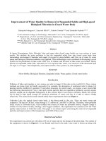
Figure 1 illustrates a basic DMT system for the case of baseband transmision in DSL [2], showing a
transmitter, a receiver, and a channel with impulse response characterized by a phase delay ∆ and a
response length ν in sample periods. N/2 tones are modulated by QAM-like two-dimensional input
Digital Duplexing
4
TD13
symbols (with appropriate N-tone conjugate symmetry in frequency) so that an N-point Inverse Fast Fourier
Transform (IFFT) produces a corresponding real baseband time-domain output signal of N real samples.
Yn
Xn
Input
bits
.
.
.
DMT
encoder
N/2 QAM
ν ∆
N/2 QAM
N
IFFT
(N)
xk
N+L
Cyclic
ext
L
N+L
Driver,
filters,
channel
DAC
N
ADC
.
.
.
FFT
(N)
Symbol
find
N, L yk
DMT
decoder
(N+L)/T =
35.328 MHz
bn , gn
table
amplitude
channel impulse response
1/T =
4000 Hz
t
∆
∆+ν
(N+L)/T =
35.328 MHz
1/T =
4000 Hz
bn , gn
table
DMT Receiver
DMT Transmitter
Dashed lines --- are control channels between xmit and rcvr.
Figure 1 - Basic DMT transmission system.
For basic DMT, the last L=ν of these samples are repeated at the beginning of the packet of transmitted
samples so that N + L samples are transmitted, leading to a time-domain loss of transmission time that is
L . This ratio is the excess bandwidth. The minimum size for
L = ν is the channel impulse response
N
duration (in sampling periods) for basic DMT (later for digitally duplexed DMT, L will be the total length
for all prefix/suffix extentions and thus greater than ν ). Sometimes DMT systems use receiver equalizers
[2] to reduce the channel impulse response length and thus decrease ν . Such equalizers are common in
ADSL. Other DMT designs [3] for VDSL use a very large value of N. In either case, the objective is to
have small excess bandwidth by decreasing the ratio ν N . In both DMT ADSL and VDSL, the excess
bandwidth is 7.8 %. VDSL uses digital duplexing, which is explained later in Subsection 2.2.
The IFFT of the DMT transmitter implements the equation
xk =
1
N
N −1
∑ Xn ⋅e
j 2Nπ nk
n =0
x k k=0,…,N-1 are the N successive time-domain transmitter outputs (the prefix is trivial repeat of
last ν ). The values X n are the two-dimensional modulated inputs that are derived from standard QAM
where
constellations (with the number of bits carried on each "tone" adaptively determined by loading as in [2]
and stored in the
bn , g n tables at both ends). To produce a real time-domain output, X n = X N* − n in the
ubiquitous case that N is an even number. In ADSL, N=512, while in VDSL, N=8192.
N + ν samples is transmitted every T seconds for a sampling rate of N + L T . With
1
One packet of
T
= 4000 Hz in
ADSL and VDSL, the sampling rates are 2.208 MHz and 35.328 MHz respectively, leading to a cyclic
prefix length of ν = L = 40 samples in ADSL and a cyclic-extension length of L=640 samples in VDSL.
The extension length in VDSL also includes the cyclic suffix to be later addressed in Subsection 2.2.
When the cyclic extension length is equal to or greater than the impulse-response length of the channel (
L ≥ ν ), DMT decomposes the transmission path into a maximum of N/2 independent simple transmission
channels that are free of intersymbol interference and that can be easily decoded. The receiver in Figure 1
Digital Duplexing
5
TD13
extracts the last N of the N + L samples in each packet at the receiver (when no cyclic suffix is used ) and
forms the FFT according to the formula
N −1
Yn = ∑ y k ⋅ e
− j 2Nπ nk
k =0
where the reindexing of time is tacit and really means samples corresponding to times
k = L + 1 ,..., L + N in the receiver. The receiver must know the symbol alignment and cannot
execute the FFT at any arbitrary phase of the symbol clock. If the receiver were to be somehow offset in
timing phase, then time-domain samples from another adjacent packet would enter the FFT input,
displacing some corresponding time-domain samples from the current packet. For instance, suppose the
FFT executed m sample times too late, then the output would be
~ N − m−1
− j 2π nk
Yn = ∑ y k + m ⋅ e N +
k =0
N −1
∑ u N −m+ k ⋅ e
− j 2Nπ nk
k = N −m
where u k are samples from the next packet that are unwanted and act as a disturbance to this packet.
Furthermore, m samples from the current packet were lost (and the rest offset in phase). Thus,
~
Yn = Yn + E n
E n is a distortion term that includes the combined effects of u k , the missing terms y k , and the
timing offset in the packet boundary. E n =0 only (in general) when the correct symbol alignment is used
where
by the receiver FFT. DMT systems easily ensure proper phase alignment through the insertion of various
training and synchronization patterns that allow extraction of correct symbol boundary.
It is important to note that the FFT of any other signal with the same N might also have such distortion
unless the symbol boundaries of that signal and the DMT signal were coincident. In the later case of time
coincidence, the FFT output is simply the sum of the two signals' independent FFTs. Indeed the receiver
would have no way of distinguishing the two signals and would simply see them as the sum in the timecoincident case.
The second signal could be the opposite-direction signal leaking through the imperfect hybrid in VDSL, but
the transmitted and received symbols must be aligned in time. When they are aligned and frequency
division duplexing is used, tones are zeroed in one direction if used in the other. Then, the sum at the FFT
output is simply either the upstream or the downstream signal, depending on the duplexing choice for the
set of indices n. No zeroed tones are necessary between upstream and downstream frequency bands as that
is simply a waste of good undistorted DMT bandwidth. No analog filtering is necessary -- the IFFT, cyclicprefix, and the FFT do all the work IF the system is fortunate enough to have time-coincidence of the two
DMT signals traveling in opposite directions. The establishment of time coincidence of the symbols at
both ends of the loop is the job of the cyclic suffix, which the next subsection addresses. In other words,
the FFT works on any DMT signal of packet size N samples, regardless of source or direction as long as the
packet is correctly positioned in time with respect to the FFT. This separation is not easily possible unless
the DMT signals are aligned - thus VDSL DMT systems ensure this alignment through a cyclic suffix to be
subsequently described.
Table 1 provides a comparison and summary of DMT use in ADSL and in VDSL. Note that DMT VDSL
uses digital frequency-division multiplexing (FDM) and spans exactly 16 times the bandwidth at its highest
bandwidth use. This full bandwidth form is actually optional and the default values are shown in
Digital Duplexing
6
TD13
parenthesis on the right, with the default actually being exactly 1/2 the full. Default DSL settings may also
be used on long loops by the equipment because the cyclic-prefix penalty is then less bandwidth at 650 kHz
instead of 1.3 MHz. ADSL uses 86 kHz (recall it is much narrower band), but has an additional
approximately 40 kHz bandwidth loss between upstream and downstream from analog-duplexing filters
(some echo-cancelled implementations avoid this loss in ADSL).
ADSL
VDSL (default)
FFT Size
512
8192 (4096)
# of tones
256
4096 (2048)
Cyclic ext
length
L = ν = 40
L = 640 ≥ ν + ∆
Sampling rate
2.208 MHz
35.328 (17.664) MHz
bandwidth
1.104 MHz
17.664 (8.832) MHz
duplexing
Analog FDM
Digital FDM
Tone width
4.3125 kHz
4.3125 kHz
86 kHz (prefix)
+40 kHz (filters)
1.3 MHz (650 kHz)
(no filters)
Excess bandwidth
Table 1 - Comparison of DMT for ADSL and VDSL
2.2 Cyclic Suffix
The cyclic suffix occurs at the end of a DMT symbol (the opposite side of the cyclic prefix) and could
repeat for instance the first 2∆ samples of the DMT symbol (not counting the prefix samples) at the end
as in Figure 2b, where ∆ is the phase delay in the channel (phase delay or absolute delay, not group delay,
which is related to ν). A symbol is then of length N+L . The value for L must be sufficiently large that it
is possible to align the DMT symbols, transmit and receive, at both ends of the transmission line. Clearly
alignment at one end of a loop-timed line 1 is relatively easy in that the line terminal (LT) for instance need
only wait until an upstream DMT symbol has been received before transmitting its downstream DMT
symbols in alignment on subsequent boundaries. Such single-end alignment is often used by some
designers to simplify various portions of an ADSL implementation. The alignment is not necessary unless
1
Loop-timing of the sample clock means that the NT (VTU-R) uses the derived sample clock from the
downstream signal as a source for the upstream sample clock in DMT.
Digital Duplexing
7
TD13
digital duplexing is used. However, alignment at one end almost surely forces misalignment of symbol
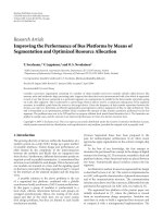
boundary at the NT as in Figure 2a.
Symbols thus misaligned at NT (VTU-R)
Symbols aligned at LT (VTU-O)
pre
3
11
2
0
∆=3, ν =2
ds DMT symbol
pre
channel
pre
Master
Clock
(all times
Discrete)
master
clock
-3
0
pre
11
Tx-LT
8
us DMT symbol
-3 -1
(NT not aligned)
Rx-NT
ds DMT symbol
-3 -1
us DMT symbol
2
14
5
0
3
5
Tx-NT
8
14
Rx-LT
-3
us prefix
-1
-1
0
0
us prefix
ds prefix
2
us symbol
2
3
3
ds prefix
5
8
11
5
ds symbol
us symbol
8
ds symbol
11
14
Figure 2a - DMT symbol alignment without cyclic suffix.
In Figure 2a , let us suppose that N=10, ν=2, and that the channel phase delay or overall delay is ∆ = 3 .
The reader can pretend they have a master time clock and that the LT begins transmitting a prefixed DMT
symbol at time sample 0 of that master clock. The first two samples at times 0 and 1 are the cyclic prefix
samples, followed by 10 samples of the DMT symbol, that is at times 0 through 11. At the receiver, all
samples undergo an absolute delay of 3 samples (in addition to the dispersion of ν= 2 samples about that
average delay of 3) . Thus, the cyclic prefix' first sample appears in the network terminal (NT) at time 3 of
the master clock and the DMT symbol runs from time 3 to time 14. The samples used by the receiver for
the FFT are samples 5 through 14, while samples 3 and 4 are discarded because they also contain remnants
from a previous DMT symbol. The LT has DMT symbol alignment in Figure 2a, so that it also received
the upstream prefix first sample at time 0 and continued to receive the corresponding samples of the
upstream DMT symbol until time 11. Thus, the DMT symbols are aligned at the LT. However, in order
for the upstream DMT symbol to arrive at this time, it had to begin at time -3 in the NT. Thus the
upstream symbol transmitted by the NT occurs in the NT at times -3 through 8 of the reader's master clock.
Clearly, the DMT symbols are not aligned at the NT.
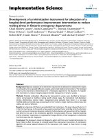
In Figure 2b, a cyclic suffix of 6 samples is now appended to DMT symbols in both directions, making the
total symbol length now 18 samples in duration (thus slowing the symbol rate or using excess bandwidth
Digital Duplexing
8
TD13
indirectly). The LT remains aligned in both directions and transmits the downstream DMT symbol from
master-clock times 0-17. These samples arrive at the NT at times 3-20 of the master clock, with valid
times for the receiver FFT now being 5-14, 6-15, … 11-20. Each of these windows of 10 successive
receiver points carry the same information from the transmitter and differ at the FFT output by a trivial
phase rotation on each tone that can easily be removed. The upstream symbol now transmits
Symbols aligned with suffix in 5-14 slot at NT (VTU-R)
Symbols aligned at LT (VTU-O)
0
11
2
pre
ds DMT symbol
-3
17
∆=3, ν =2
suf
channel
pre
us DMT symbol
3
last suf
pre
ds DMT symbol
8
-1
-3
suf
14
5
pre
us DMT symbol
suf
valid us symbol
Master
Clock
(all times
Discrete)
0
master
clock
-3
11
2
Tx-LT
17
-3 -1
Rx-NT
0
3
Tx-NT
(NT also aligned)
5
8
14
Rx-LT
-3
us prefix
-1
-1
0
0
us prefix
ds prefix
2
us symbol
2
3
3
ds prefix
5
5
ds symbol
us symbol
8
8
valid us symbol
ds symbol
11
14
ds suffix
11
us suffix
ds suffix
17
Figure 2b - DMT symbol alignment at both LT and NT through use of suffix.
corresponding valid DMT symbols from time -1 to time 8, also 0-9, 1-10, and the last valid upstream
symbol is time 5-14. At the NT, the first downstream valid symbol boundary from samples 5-14 and the
last upstream valid symbol boundary, also at samples 5-14, are coincident in time --- thus the receiver's FFT
can correctly find both LT and NT transmit signals by executing at sample times 5-14 without distortion of
or interference between tones. At this time only (for cyclic suffix length 6), the receiver FFT and IFFT can
be executed in perfect alignment, and thus downstream and upstream signals are perfectly separated. This
DMT system in Figure 2b has symbol-rate loop timing, and thus a single FFT can be used at each end to
extract both upstream and downstream signals without distortion. (There is still an IFFT also present for
the opposite-direction transmitter.) This loop is now digitally duplexed.
Note the cyclic suffix has length double the channel delay (or equivalently was equal to the round-trip
delay) in the example. More generally, one can see that from Figure 2b that NT symbol alignment will
occur when the equivalent of time 5, which is generally ν + ∆ , is equal to the time -3+2+Lsuf, =
− ∆ + ν + Lsuf . Equivalently Lsuf=2∆. In fact, any
Lsuf ≥ 2∆
is sufficient with those cyclic suffix lengths that exceed 2∆ just allowing more valid choices for the FFT
boundary in the NT. For instance, had we chosen a cyclic suffix length of 7 in our example, then valid
Digital Duplexing
9
TD13
receiver FFT intervals would have been both 5-14 and 6-15. This condition can be halved using the timing
advance method in Subsection 2.2.1
2.2.1
Timing Advance at LT
Lsuf ≥ ∆ . This
method uses a timing advance in the LT modem where downstream DMT symbols are advanced by ∆
Figure 2c shows a method to reduce the required cyclic suffix length by one-half to
samples. The two symbols now align at both ends at time samples 2-11, and the cyclic suffix length is
reduced to 3 in the specific example of Figures 2a, 2b, and 2c. Thus, for VDSL with timing advance, the
total length of channel impulse-response length and phase delay must be less than 36 µs , which easily is
achieved with significant extra samples for the suffix in practice. In VDSL, the proposal for L is 640
when N=8192. The delays of even severe VDSL channels are almost always such that the phase delay
∆ plus the channel impulse-response length ν are much less than the 36µs cyclic extension length (if not, a
time equalizer, see [2], needs to be used, but this case has not been observed in practice). One notes that
the use of the timing advance causes the transmitters and receivers at both ends to all be operational at the
same phase in the absolute time measured by the master clock.
Symbols aligned at NT (VTU-R) with suffix in 2-11 slot
Symbols aligned at LT (VTU-O) with suffix in 2-11 slot
-3
pre
-1
8
-3
11
ds DMT symbol
∆=3, ν =2
suf
channel
pre
us DMT symbol
suf
0
11
2
last suf
pre
ds DMT symbol
-1
-3
pre
8
us DMT symbol
suf
valid us symbol
Master -3 -1 0
Clock
(all times
master
Discrete)
clock
-3
11
2
Tx-LT
14
-3 -1
Rx-NT
Tx-NT
(NT also aligned)
2
8
11
Rx-LT
-3
ds prefix
us prefix
-1
-1
0
0
0
2
0
ds prefix
2
us prefix
2
ds symbol
2
us symbol
3
5
valid ds symbol
valid us symbol
us symbol
ds symbol
8
8
us suffix
ds suffix
11
11
ds suffix
us suffix
14
Figure 2c - Illustration of cyclic suffix and LT timing advance.
Digital duplexing thus achieves complete isolation of downstream and upstream transmission with no
frequency guard band -- there is however, the 7.8% cyclic extension penalty (which is equivalent to 1.3
MHz loss in bandwidth in full VDSL and 650 kHz loss in the default or "lite" VDSL). Thus it is not
correct, nor appropriate, to place frequency guard bands in studies of DMT performance in VDSL. This
mistake has been made by several groups recently and leads to erroneous conclusions. There is no
technical justification for the double penalty or adding frequency guard bands, it is simply wrong.
Digital Duplexing
10
TD13
3. Digital Duplexing
Digital duplexing in concept allows arbitary assignment of upstream and downstream DMT tones, which
with FDM VDSL means these two sets of upstream and downstream tones are mutually exclusive. On the
same line, there is no interference or analog filtering necessary to separate the signals, again because the
cyclic suffix (for which the equivalent of 1.3 MHz of bandwidth has been paid or 650 kHz in default
VDSL) allows full separation even between adjacent tones in opposite directions via the receiver's FFT.
However, while theoretically optimum, one need not "zipper" the spectrum in extremely narrow bands, and
instead upstream and downstream bands consisting of many tones may be assigned as in [4]. Some
alternation between up and down frequencies is universally agreed as necessary for reasons of spectrum
management and robustness, although groups differ on the number of such alternations.
3.1 Crosstalk
Analysis of NEXT between neighboring VDSL circuits needs to consider two possibilities:
(1) synchronization of VDSL lines
(2) asynchronous VDSL lines
The first case of synchronous crosstalk is trivial to analyze and implement with FDM. Adjacent lines have
exactly the same sampling clock frequency (but not necessarily the same symbol boundaries). There is no
NEXT from other synchronized VDSLs with FDM as will be clear shortly.
The second case of asynchronous self-VDSL NEXT is more interesting and has been studied in [5]. In this
case, the sidelobes of the modulation pulse shapes for each tone are of interest.
[
]⋅ w (t) = 2 X
A single DMT tone consists of the sinusoidal component
xn ( t ) = X n ⋅ e
j 2Nπ ⋅ NT+ν ⋅nt
+ X −n ⋅ e
− j 2Nπ ⋅ NT+ν ⋅nt
T
n
⋅ cos( 2πf 0 nt + ∠X n ) ⋅ wT ( t ) ,
where f 0 = 2Nπ ⋅ NT+ν or 4.3125 kHz in ADSL and VDSL, and wT ( t ) is a windowing function that is a
rectangular window in ADSL, but is more sophisticated and exploits digital-duplexing's extra cyclic suffix
and extra cyclic prefix in VDSL. Figure 3 shows the relative spectrum of a single tone with respect to an
adjacent tone for the rectangular window.
Note the notches in the crosstalker's spectrum at the DMT frequencies, all integer multiples of f0. Thus, the
contribution of other VDSL NEXT will clearly be zero if all systems use the same clock for sampling,
regardless of DMT symbol phase with respect to that clock. This is an inherent advantage of DMT systems
with respect to themselves since it is entirely feasible that VDSL modems in the same ONU binder group
could share the same clock and thus have no NEXT into one another at all.
When the sampling clocks are different, however, the more that sampling clocks of VDSL systems differ,
the greater the deviation in frequency in Figure 3 from the nulls, allowing for a possibility of some NEXT.
Studies of such NEXT for DMT digital duplexing are highly subjective and depend on assumptions of
clock accuracy, number of crosstalkers with worst-case clock deviation, and the individual contribution to
NEXT transfer function of each of these corresponding worst-case crosstalkers. Nonetheless, reasonable
implementation renders NEXT of little consequence between DMT systems.
If the VDSL PSD transmission level is S=-60 dBm/Hz, and the crosstalk coupling is approximated by
(m / 49) .6 ⋅ 10 −13 ⋅ f 1.5 for m crosstalkers the crosstalk PSD level is
2
.6
S xtalk ( f ) = S ⋅ (1 / 49) ⋅ f 1.5 ⋅ sin c f .
f0
The peak or sidelobes can be only 12 dB down with such rectangular windowing of the DMT signal, as in
Figure 3. Asynchronous crosstalk may be such that especially with misaligned symbol boundaries that a
really worst-case crosstalker could have its peak sidelobe aligned with the null of another tone (this is
Digital Duplexing
11
TD13
actually rare, but clearly represents a worst case). To confine this worst-case, the methods of the next two
subsections are used.
1
0.9
0.8
0.7
0.6
0.5
0.4
0.3
0.2
0.1
0
-10
-8
-6
-4
-2
0
2
4
6
8
10
Figure 3a - magnitude of windowed sinusoid versus frequency - note notches at DMT frequencies.
3.2 Windowing of extra suffix and prefix
pre
DMT symbol
suf
pre
Extra
suffix
Extra
prefix
Total cyclic extension is 640 samples
Figure 4a - Illustration of windowing in extra suffix/prefix samples - smooth connection of blocks
without affecting necessary properties for digital duplexing.
This tutorial explains how windowing can be implemented without the consequence of intermodulation
distortion when digital duplexing is used. Windowing in digitally duplexed DMT exploits the extra
samples in the cyclic suffix and cyclic prefix beyond the minimum necessary. Since the cyclic extension is
always fixed at L=640 samples in VDSL, there are always many extra samples. Figure 4a shows the basic
idea: the extra suffix samples are windowed as shown with the extra extension samples now being split
between a suffix for the current block and a prefix for the next block. The two are smoothly connected by
windowing, a simple operation of time-domain multiplication of each real sample by a real amplitude that
is the window height. The smooth interconnection of the blocks allows for more rapid decay in the
frequency domain of the PSD, which is good for crosstalk and other emissions purposes. A rectangular
window will have the per tone (baseband) roll off function given by
Digital Duplexing
12
WT (
TD13
sin πf
f0
f)=
πf
f
0
or the so-called "sinc" function in frequency. Clearly, a smoother window could produce a more rapid
decay with frequency. A logical and good choice is the so-called raised-cosine window. Let us suppose
that the extra cyclic suffix contains 2L' +1 samples in duration, an odd number. 2 Then, the raised cosine
function has the following time-domain window (letting the sampling period be T') with time zero being
the first point in the extra cyclic suffix and the last sample being time 2L'T' and the center point thus L'T':
wT ,rcr ( t ) =
t
1
1 + cos π ⋅
t = 0,..., L' T ' ,...,2 L' T '
2
L' T '
One notes the window achieves values 1 at the boundaries and is zero on the middle sample and follows a
sampled sinusoidal curve in between. The points before time L'T' are part of the prefix of the current
symbol, while the points after L'T' are part of the suffix of the last symbol.
The overall window (which is fixed at 1 in between) has Fourier transform (let
insignificant phase term
WT (
α=
L'
L−L'
), ignoring an
sin πf cosαπf
f0
f0
L'
f)= ⋅
⋅
2 .
α πf
f 1 − 2απf
f0
0
Larger α means faster roll-off with frequency. This function is improved with respect to the sinc function,
especially a few tones away from an up/down boundary. Reasonable values of α corresponding to 100-200
samples will lead to even the peaks of the NEXT sidelobes below -140 dBm/Hz at about 200 kHz spacing
below 5 MHz.
The reduction becomes particularly pronounced just a few tones away, and so at
maximum, a very small loss may occur with asynchronous crosstalk. Thus, signals other than 4.3125kHz
DMT see more crosstalk, but within 200 kHz of a frequency edge, such NEXT is negligible. This
observation is most important for studies of interference into home LAN signals like G.pnt, which at
present almost certainly will not use 4.3125 kHz spaced DMT.
3.2.1 Overlapped Transmitter Windows
Figure 4b shows overlapped windows in the suffix region. The smoothing function is still evident and
some symmetrical windows (i.e., sq-root cosine) have constant average power over the window and the
effective length of the window above L' can be doubled, leading to better sidelobe reduction. This
overlapping requires an additional 2L'+1 additions per symbol, a negligible increase in complexity.
pre
DMT symbol
suf
pre
Extra
suffix
Extra
prefix
Figure 4b - Illustration of overlapped windowing.
2
If even, just pretend it is one less and allow for two samples to be valid duplexing endpoints.
Digital Duplexing
13
TD13
3.2.2 Receiver windowing
Receiver windowing can also be used as in [5] to again filter the extra suffix and extra prefix region in the
receiver, resulting in further reduction in sidelobes. Figure 5 shows the effect on VDSL NEXT for both the
cases of a transmitter window and both a transmitter and receiver window. Note the combined windows
has very low transmit spectrum (well below FEXT in a few tones) and below -140 dBm/Hz AWGN floor
by 40 tones. If it is desirable to further reduce VDSL NEXT to zero, an additional small complexity can be
introduced as in the next subsection with the adaptive NEXT canceller.
Figure 5 - extracted from [5]. PS= transmitter windowing (pulse shaping) and window here means
receiver window. This simulation is for a 1000 m loop of .5 mm transmission line (24 gauge).
3.2.3 Adaptive NEXT canceller for digital duplexing
Figure 6 illustrates an adaptive NEXT canceller and its operation near the boundary of up and down
frequencies in a digitally duplexed system. Figure 6 is the downstream receiver, but a dual configuration
exists for the upstream receiver. Note any small residual upstream VDSL NEXT left after windowing in the
downstream tone n (or in tones less than n in frequency index) must be a function of the upstream signal
extracted at frequencies n+1, n+2, … at the FFT output. This function is a function of the frequency offsets
between all the NEXTs and the VDSL signal. This timing-clock offset is usually fixed, but can drift with
time slowly. An adaptive filter can eliminate the NEXT as per standard noise cancellation methods [9]. A
very small number of tones are required for the canceller per up/down edge if transmit windowing in
Subsection 3.2.1 and receiver windowing in Subsection 3.2.2 are used. Adaptive noise cancelation can be
Digital Duplexing
14
TD13
used to make VDSL self-NEXT neglible with respect to the -140 dBm/Hz noise level. This allows full
benefit of any FEXT reduction methods that may also be also in effect (note the NEXT is already below the
FEXT even without the NEXT canceller, but reducing it below the noise floor anticipates a VDSL system's
potential ability to eliminate or dramatically reduce FEXT), see for instance TD16 of this meeting [10]
downstream
n
-
upstream
n+1
×
FFT
Cn +1,n
n+p
FEQ
+
..
.
FEQ error
For adaptive
update of noise
canceller coefficients
to bit-swap
algorithm
×
Cn +p ,n
Noise Canceller
Figure 6 - Adaptive noise canceller for elimination of VDSL self-NEXT in asynchronous VDSL
operation. Shown for one upstream/downstream boundary tone (can replicated for each up/down
transition tone that has NEXT distortion with asynchronous VDSL NEXT). No canceller necessary if
NEXT is synchronous.
3.4 ADC
Digital duplexing admits the possibility of a large signal in one direction leaking through a hybrid circuit
and entering the receiver along with highly attenuated signals from the line. With respect to analog
duplexing methods or ping-pong (time-division duplexing), this requires an extra 2 bits of ADC resolution,
which has been verified carefully by several authors [6]. This forces ADC requirements from 10 bits to 12
bits in VDSL at 35 MHz speeds, which is feasible [6] at low power and small die size. This precisional
increase can be mitigated through various oversampling and digital hybrid methods to return to 10-bit
precision, but such measures do not seem necessary. Some proponents of alternatives to digital duplexing
have conjectured more bits are necessary, but often rely on unrealistic assumptions on analog front-end
designs. It is easy to use standard methods to make best use of available precision without affecting the
zero-guard-band feature of digital duplexing. The reader is referred to [6], which was conceded to be
accurate in the August 1999 ITU SG15/Q4 meeting in Nuremberg Germany by an expert and proponent of
analog-duplexing (Dr. G. Ungerboeck) after significant discussion. Thus, the accepted complexity penalty
of digital duplexing in analog is an extra 2 bits in the analog to digital converter, see [6]. The reader can
assess whether the merits of digital duplex outweigh the requisite precision increase.
Digital Duplexing
15
TD13
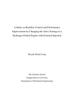
4 Example
To illustrate the utility of digital duplexing, this section provides an example of proper bandwidth
assignment and calculation of two recently proposed duplexing plans for digital duplexing in [7] and for
analog duplexing in [8], which are shown here in Figure 7.
Step 1:
ADSL
U
Step 2:
VSDSL
D U
U D
D
1.1
.2
D
U
Step 3
VADSL
5.3
U
D
3.6
4.55
10
7.1
10.15
7.25
Universal - Alliance DMT
(digital duplex) [7]
U
14.6
D
D
6.05
U
D
D
3.1 3.5 4.0
1.5 1.9 2.0
.8
U
D
U
D
Step 4:
BDSL
17.7
4-BAND analog [8]
U
8.75
12
17
Figure 7 - 2 frequency plans used in example.
Note the first plan uses digital duplexing, allowing frequency bands in opposite directions (U=upstream and
D=downstream) to be adjacent. The gaps in the first plan correspond to known amateur radio bands where
signals are zeroed in both directions to prevent egress. The second plan presumes analog duplexing and so
gaps are left between directions of transmission as analog (and/or digital) filters are necessary to separate
the bands and require nonzero transition regions. The penalty of excess bandwidth in the first system is the
1.3 MHz equivalent of the 640 sample cyclic extension. This plan then roughly uses about 16.4 MHz of
line bandwidth. The second plan leaves frequency guard intervals of 6.2 MHz, almost 4 times the excess
bandwidth penalty of digital duplexing (and saves 2 bits in the corresponding ADC requirement or some
other equivalent complexity).
On short loops, this entire 6.2 MHz is lost, while on longer loops a fraction of it is lost, but usually at least
3 MHz. On long loops, the digital-duplex excess bandwidth reduces to 650 kHz. At even an average bit
density of 2-3 bits/Hz, the difference between analog and digital duplexing can thus be as much as 15 Mbps
and often would be at least 4 Mbps of bi-directional bandwidth. This 4-15 Mbps performance loss is very
large. The digital duplexing bandwidth advantage is evident even if only 4 bands were to be used in some
modified version of the universal plan in Figure 7. Indeed, ANY number of bands can be used with the
SAME 1.3 MHz (full, or 650 kHz default) excess bandwidth penalty. Analog duplexing penalties by
contrast increase with the number of bands - thus analog duplexing methods often must use 4 bands or less
to avoid the bandwidth loss, but then have a more difficult trade-off in terms of meeting performance
requirements as a consequence.
Recently, unbundled access has become a requirement in both the ITU and ANSI T1E1.4, which means that
asymmetric and symmetric VDSL transmission must share the same binder with the same spectrum within
a national boundary. This mixture stresses VDSL performance requirements. The extra bandwidth use
afforded by digital duplexing helps mitigate this loss in performance. Analog duplexing on the other hand
is highly wasteful of a system resource that is not easily discarded when range/rate trade-offs are as strained
as they are in VDSL.
5 Conclusions
This tutorial hopes to provide assistance to those desiring to compute the performance of digitally duplexed
transmission systems, using DMT as an example to understand digital duplexing. The analysis within
Digital Duplexing
16
TD13
shows how a time-domain "excess bandwidth" penalty is paid to allow upstream and downstream
transmission bands to be immediately adjacent. Such digital duplexing was not used in earlier forms of
DMT, most notably the DMT standardized in ADSL. Thus, performance analysis of a VDSL DMT system
is not identical to that of a DMT ADSL system. To summarize, this contribution also provides these
guidelines for accurate simulation (for instance using the FSAN simulation tool)
1. Guard bands should not be placed between upstream and downstream frequency bands
2. The overall overhead should be set to less than 8 %
Notwithstanding the well-known transmission performance advantages of DMT in handling channels with
severe ISI and frequency-selective noises -- especially when multiband transmission is optimum--, with
respect to analog duplexing, digital duplexing is a separate advantage that has nothing directly to do with
line code. However, digital duplexing is easy with DMT as long as the cyclic suffix is used to ensure the
DMT system is symbol-rate loop timed, which means that DMT symbol boundaries are aligned at both
ends.
6. References
[1]
M. Isaksson et al, “Zipper -- A Flexible Duplex Scheme for VDSL,” ANSI Contribution
T1E1.4/97-016, February 3, 1997, Austin, TX.
[2]
T. Starr et al, Understanding Digital Subscriber Line Technology, Prentice-Hall: Upper Saddle
River, NJ, 1999.
[3]
M. Peeters and VDSL Alliance, "Physical Medium Specific Specification for VDSL," ANSI
Contribution T1E1.4/99-275R1, Baltimore, MD, August 23, 1999.
[4]
J. Cioffi et al, “Robust Duplexing in VDSL,” ETSI TM6 Contribution TD14, September 1999,
Edinburgh, Scotland.
[5]
F. Sjöberg, R. Nilsson, et al, "Asynchronous Zipper," ICC'99, Atlanta GA. June 1999. See also M.
Isaksson, F. Sjöberg et al., "Pulse Shaping with Zipper - Spectral Compatibility and Asynchrony",
ANSI contribution T1E1.4/98-041, March 2-6, 1998, Austin, Texas
[6]
J. Cioffi et al, ADC precision contributions - See BOTH ANSI T1E1.4 contributions 99-274R2
(June, 1999, Ottawa) and 99-274R3 (August, 1999 Baltimore).
[7]
VDSL Alliance, "A Universal Spectrum Plan Proposal for DMT," ANSI Contribution T1E1.4/99274R2, Baltimore, MD, August 23, 1999.
[8]
Q. Wang, "VDSL Spectrum Plan Proposal," ANSI Contribution 99-345, Baltimore, MD, August
23, 1999.
[9]
J. Triechler et al, Theory and Design of Adaptive Fitlers, Wiley: NY, 1987.
[10]
J. Cioffi et al, "Vectored VDSL for Universal Band Allocation," ETSI TM6 Contribution TD16,
Edinburgh, Scotland, September 1999.
Acknowledgement:
The authors would particularly like to thank Dr. Krista Jacobsen of Texas Instruments for detailed
comments and review of this paper. Also, special thanks to Jim Carlo of TI, Dr. Chansoo Hwang of
Samsung for their comments.
Digital Duplexing
17
TD13