báo cáo hóa học:" Research Article Improving the Performance of Bus Platforms by Means of Segmentation and Optimized Resource Allocation" ppt
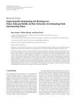
Bạn đang xem bản rút gọn của tài liệu. Xem và tải ngay bản đầy đủ của tài liệu tại đây (785.43 KB, 14 trang )
Hindawi Publishing Corporation
EURASIP Journal on Embedded Systems
Volume 2009, Article ID 867362, 14 pages
doi:10.1155/2009/867362
Research Article
Improving the Performance of Bus Platforms by Means of
Segmentation and Optimized Resource Allocation
T. Seceleanu,
1
V. Le pp
¨
anen,
2
and O. S. Nevalainen
2
1
ABB Corporate Research, Automation Networks Department, SE-72178 V
¨
aster
˚
as, Sweden
2
Department of Information Technology, University of Turku and TUCS, FIN-20014 Turku, Finland
Correspondence should be addressed to T. Seceleanu,
Received 8 August 2008; Revised 11 January 2009; Accepted 5 April 2009
Recommended by Leonel Sousa
Consider a processor organization consisting of a number of client modules and server modules (jointly called devices), like
memory units and arithmetic-logic processing units. Suppose that these devices are interconnected with a bus which is segmented
in such a way that devices connected to a particular segment can communicate in parallel to the data transfer operations going
on in the other segments. This is achieved by a control logic which is able to reserve a continuous subsequence of the segments
necessary to establish a path from the source to the target device. Given the frequency of data transfer operations between the
devices, our task is to determine an efficient segmentation and segment-to-device assignment of this on-chip architecture. This
task is formulated as an optimization problem w hich considers the amount of data transfer operations performed via the bus
segments. The problem turns out to be NP hard but we propose efficient local search-based heur istics for it. The heuristics are
applied to sample cases, and the outcome is an improved performance in terms of a shorter execution time.
Copyright © 2009 T. Seceleanu et al. This is an open access article distributed under the Creative Commons Attribution License,
which permits unrestricted use, distribution, and reproduction in any medium, provided the original work is properly cited.
1. Introduction
The growing diversity of devices within the boundaries of a
modern system-on-a-chip (SOC) brings up a great number
of possible interfaces. System design and perfor mance are
often limited by the complexity of the interconnection
between the modules and blocks that are integrated into
these devices. Furthermore, different data transfer speeds are
required as well as parallel t ransmission. A conventional bus
structure is not suitable for such designs. This is because only
one module can transmit at a time, and the signaling speed
on the bus is restricted by the large capacitive load [1] caused
by the interfaces of the attached modules and the long bus
wires.
A possible solution to the above problems is the use
of a segmented bus platform, combined with a globally
asynchronous locally synchronous (GALS) system architecture.
In this paper, a group of modules is synchronized to a
local clock, whereas interactions between such groups are
arranged asynchronously. Hence, the routing of the clock
signal and that of the clock skew are no more system
level design problems, but they are limited to each locally
synchronous module.
Premises. Segmented buses have been proposed in the
past, for multicomputer architectures [2–4]. M ore recent
approaches apply segmentation in the context of single-chip
devices.
To the best of our knowledge, the first attempt to
introduce the par titioned bus concept in the design of digital
systems is by Ewering [5]. The structure resembles a dual rail
pipelined scheme, where functional units are placed between
two buses. Symmetrically placed switches connect the bus
segments.
An illustrative analysis focused on segmented bus design
is described by Jone et al. [6].Thesystemisimplementedas
an ASIC, with specific characteristics of physical interconnect
and of the communication structure. The communication
infrastructure allows tree-like constructs, differently from the
partitioned bus approach (an ASIC style, too) taken in [5].
The segmented bus platform of the present paper was
initially introduced in [7], where the platform is viewed
from an asynchronous design perspective. Intuition was
used there in order to build a segmented bus structure and
to compare it with a nonsegmented implementation. The
2 EURASIP Journal on Embedded Systems
synchronous platform is described in [8]; arbitration policies
are addressed in [9, 10].
We consider here the resource allocation procedure
for applications running on the segmented bus platform
(SB) described in [8]. By a reasonable organization of the
hardware components and of the bus segments, one can
increase the degree of parallelism of data transfers and in
this way possibly improve the overall system performance,
expressed as the time required to perform the tasks specified
at the application level (evaluated in the number of clock
“ticks”). On the other hand, each extra seg ment means a new
switch for allowing the connectivity of the respective segment
to the rest of the platform. A balance between parallelism
and complexity of the system is therefore to be found. The
success of an SB implementation depends on the profile of
the accesses between the hardware units, on the organization
of the segments, and on the assignment of the units to the
segments.
The idea in the present paper is to organize the com-
ponent devices and the segments in such a way that the
number of parallel data transfers is maximized. We maximize
the possibilities for parallel transfers by minimizing the
amount of requests using any sing le bus segment (since
such traffic necessarily is sequential). We evaluate and try
to minimize the communication costs of data transfers to
obtain an optimal device-to-segment allocation, in terms of
performance. The cost is supposed to be linearly dependent
on the amount of data transferred l ocally (within a segment)
and globally (intersegment communication). The objective
here is to keep the inter-segment data transfers of each
segment low. Our approach assumes that the application
flow has been analyzed, and the communication patterns
have been extracted. This is followed by binding function-
ality to devices, such that a device-to-device communica-
tion mat rix can be built. We may start then considering
how the performance is affected by the bus segmentation
and resource allocation. We express the device-to-segment
allocation problem as a min-max optimization problem
and show its NP hardness. To find reasonable (although
suboptimal) solutions, we propose a generic local search
algorithm which performs a set of exchange operations
on the current candidate solution in order to proceed
toward better solutions. In practical tests, we work with
synthetic data to be able to characterize the platform
without binding it to a specific (set of) application(s).
It turns out that applications with a biased (that is, a
noneven) traffic will have a better performance on an
SB platform. The algorithms developed here are imple-
mented in the SBTool application, returning the optimal
allocation parameters, based on the communication matr ix
input.
Paper Overview. The rest of paper is organized as follows.
We continue in Section 2 by exploring existing approaches to
segmented bus architectures. In Section 3 we make a short
description of the segmented bus concept and the operation
modes on such a platform. The problem of segmenting
the bus is described in Section 4. Section 5 discusses the
time complexity of the problem and introduces a device-to-
segment allocation algorithm using local search operations.
The behaviour of proposed algorithms is evaluated with the-
oretical trafficloadsbymeansoftwoexamplesofthedevice-
to-segment allocation, in Section 6.1. Two another examples
are further analyzed, from implementation perspectives, in
Sections 6.2 and 6.3. The paper is concluded in Section 7.
2. Related Work
The on-chip multiprocessor domain has recently ceased
to exist only in theory, or at the level of microcomputer
architectures. The most popular concept for such systems is
today the network-on-chip (NOC) paradigm [11]; see Jantsch
and Tenhunen [12] for a discussion on the benefits and
challenges of NOC systems.
The SB and the NOC approaches share several advan-
tages, such as modularity, reusability, predictability, and
adaptability as well as a set of disadvantages, such as an
increased configuration process, loss of optimality, and
communication latency. Still, due to the reduced complexity
of the SB platform, compared to an NOC system, and to its
linear, compared to the two-dimensional structural aspect,
the former is closer to the traditional bus-based design
experience.
The main differences between the two architectures
reside in the centralized versus the distributed arbitration
and routing policies. As data-traffic congestions are expected
in both architectures, the SB solutions come in the shape
of carefully designed arbitration policies, while NOCs benefit
mostly from two packet traffic coordination schemes (guar-
anteed throughput (GT)—bounded latency at data stream
levels, and best-effort (BE)—no given guarantee on the
arrival time). However, in the context of computer networks,
Rexford and Shin [13] report that combining GT and BE
traffic is a fundamentally hard issue. Avasare et al. [14]
address routing policies for NOCs with centralized control,
in order to improve BE traffic characteristics. Such solutions
bring NOC closer to the communication management of the
segmented buses.
Moreover, at present day design complexity, NOCs do
not always provide the huge predicted impact on the
design process. With the exception detailed by Delorme and
Houzet [15], even for relatively complex applications such
as Motion-JPEG decoder [14]orMPEG-2encoder[16],
the number of processing nodes (routers plus the attached
processing devices) is quite low (4 and 2, resp.), while the
“element interconnect bus”—a bus architecture which, as
our SB, allows parallel transmissions—has successfully been
employed by Pham et al. in the implementation of a complex
“cell processor” [17].
Jone et al. [6] consider the mathematical principles
necessary for a sound bus partitioning and aspects of
an ASIC-style implementation. The target technology is
decisive in building the architecture, and cost functions,
as direct connections between communicating devices are
possible. The power consumption of the segmented bus is
lowered by minimizing the switch capacitance (i.e., effective
EURASIP Journal on Embedded Systems 3
capacitance) on each bus line. This is the sum of the products
of load capacitance and switching frequency. The method
produces an optimal segment tree by using a multiterminal
network flow formulation of the problem.
Wang et al. [18] study the memory usage and device
allocation on segmented buses. Their partitioning schemes
emerge from employing a Data Transfer and Storage Explo-
ration methodology, for system level memory management.
Hence, the segmentation/partitioning issues are not the focus
of their study.
Srinivasan et al. in [19] give a method for minimizing
the power consumption of their segmented bus platform.
They(asalsowe)havedifferent operating frequencies at each
bussegment.Thecitedstudy,however,doesnotoffer a clear
description of the practical implementation issues, and of the
architectural features of the platform.
Lahiri et al. [20] discuss impact of communication
protocols on the optimal segmentation problem. Their
segmented bus architecture is memoryless. The approach
introduces a simulation-based trace extraction, which is used
to indicate the communication patterns in processing.
Current Study Approach. In comparison to the above
research efforts, our problem setting is different in several
aspects. Some of them are depicted here as follows.
(i) The selection of FPGAs (versus ASIC [5, 6, 21], etc.)
as the implementation technology imposes specific
constraints related to the placement of devices on the
platform. Strict localization of the clock domains is
extremely important in FPGA implementations, due
to the restrictions on routing global signals (such as
clocks). Therefore, we use the “LogicLocks” feature
of Altera design tools [22] in order to group together
devices operating in the same clock domain. A tree-
like structure would imply the adjacency of at least
three of such regions, around a single border unit.
Given the geometry of the regions and the restrictions
on placement, this is most often hard (or even impos-
sible) to implement. Hence, we restrict ourselves
only on the linear organization of bus segments
(extensible to a circular arrangement)—thus, we do
not allow a tree-like segment organization.
(ii) Our objective is to maximize the parallelization and,
at the same time, to minimize the frequency of inter-
segment transactions, as opposed to minimizing
the overall usage of power consumed by the bus
segments, in [6, 21].
(iii) We do not fix (by a relaxation of the problem) the
device topology but allow a free search for the order
of the devices.
More generally, we recognize that the bus segmentation
problem is clearly a combinatorial optimization problem.
While in such problems methods like local search, simulated
annealing, and genetic algorithms are typically the best ones,
we omit the latter, since simulated annealing and local search
methods are very natural options to apply for this particular
problem.
The approach taken in [19]providesarangeoffrequen-
cies that are coded into the details of the genetic algorithms
developed to solve the allocation problem. In contrast, we
take a more liberal view and do not restrict our models to a
given range of frequencies. These will result in the process
of selection for the functional modules (IPs) and must be
selected to suit the application(s) at hand, being thus a later
step in the design methodology.
Compared to [20], we consider a model where commu-
nication instances are not correlated, allowing for considera-
tion of multiple application contexts.
3. Segmented Bus Architecture
A segmented bus is a bus which is partitioned into two
or more segments. Each segment acts as a normal bus for
the associated modules and operates in parallel with other
segments. Neighboring segments can be dynamically linked
to each other in order to establish a connection between
modules located in different segments. In this case, all
dynamically connected segments act as a single bus. The first
step in the design is to organize a communication scheme
that allows the components of a system to efficiently transfer
data over the shared bus.
A bus-based system consists of three kinds of compo-
nents (subsystems): maste rs, slaves,andarbiters.Amaster is a
device that requests services from other devices, the slaves.
Only one master at a time may transfer data on the bus,
thus there is need for arbit ration. In a conventional single-
bus approach, a master-slave connection reserves the whole
bus, regardless of the relative placement of these devices.
TheSBapproachallowsaconnectiontoreserveonlyasmall
portion of the bus, while other devices may use the remaining
segments.
The SB platform is thought as having a single central
arbitration (CA) unit and local segment arbitration (SA)
units. The SA decides which master within the segment will
get access to the bus in the following transfer burst. If a
specific master requires an inter-segment connection, the
request is forwarded to the CA, which performs the same
operation at the bus level, deciding which segments need
to be dynamically connected to establish a link between the
granted master and the target slave. Hence, the interface
components between a djacent segments, the segment bridges
(or border units), are controlled (opened and closed) by the
CA; see Figure 1 for a high level diagram of the SB system.
Operations on a Segmented Bus. From a local arbitration
standpoint, the operation on a specific segment may proceed
in three modes. These depend on the location of the granted
master and the target slave, taking a local arbitration unit as
a reference point. Thus, we have (i) a local maste r-local slave
situation, which means that the master and the slave are both
situated in the same segment with the SA, (ii) a local master-
external slave situation: only the granted master resides in
the same segment as the SA, and (iii) an external master-
local/external slave situation: only the target slave possibly
resides in the same segment as the SA.
4 EURASIP Journal on Embedded Systems
System
P core
ALU
Memory
block
ALU
DSP
DSP
SA
SA
SA
CA
µ
µP
core
Figure 1: The SB architecture.
In all the situations, the master connects to the slave
after a four-phase signaling protocol between the master,
and the corresponding SA has been executed. The latter also
monitors the communication, by counting the number of
data words being transferred from the master, in the cases
(i) and (ii) above.
In the case (ii), the master signals the request for another
segment by correspondingly selecting the slave address. First
lines of this address, which encode the target segment
number, are also read by the SA which forwards the request
to the CA, in order to obtain passage to the slave. While
the master is waiting for the response from the CA, another
master may obtain the bus control for an intra-segment
local operation. Whenever the acknowledgment from the CA
arrives, and the possible local operation has been completed,
the SA passes the bus control to the requesting master which
then accesses the remote target slave through a number of
dynamically connected bus segments.
Notice that all the components in the SB implementation
are mutually asynchronous devices. Therefore, communi-
cation between them follows rules posed by the applied
handshake protocols that must consider also the necessary
synchronization elements. A more detailed block description
of segment components and signals is given in Figure 2,
while the protocol and functional descriptions can be found
elsewhere [8].
The performance speedup of SB platform is based on
the overlaps between local activities in different segments
and between inter-segments t ransfers and local activities.
Arbitration processing is not an issue from a time per-
spective, unless the SA or the CA were idling pr ior to a
decision; otherwise, arbitr ation procedures also overlap with
transaction activities.
4. Problem Statement
Consider a specific case of a bus with n
s
= 3 segments and
n
= 8devices,asinFigure 3. For example, a data transfer
between D
4
and D
6
reserves the segment 2 only. On the other
hand, a transfer between D
2
and D
8
reserves all the three
Table 1: An example of communication matrix C. The amount c
i,j
of data transfers per time unit from source i to target j.
i \ j 12345678
1 0505270300
2 6008590712
3 4604056057
4 6 3500 2604 3
5 5080660401
6 2 440504 0 5 3
7 015406090
8 108514800
segments. The traffic between devices is defined b y a device-
to-device communication m atrix C (c
i, j
;1≤ i, j ≤ n) giving
the amount of data transfer requests per time unit between
each device pair (i, j); see Table 1. Denote the total traffic
with C
sum
=
i, j
c
i, j
.
For each segment k (k
= 1, 2, , n
s
) we can calculate the
total amount of data transfers over that segment as the sum
of transfers which have
(1) source and target device in seg ment k (t
k,1
),
(2) source in segment k, target elsewhere (t
k,2
),
(3) target in segment k, source elsewhere (t
k,3
), or
(4) source in segment i and target in j,wherei<k< jor
i>k>j(t
k,4
).
Here t
k, j
denotes the amount of data transfers per time unit
in case j
= 1, ,4.Figure 4 shows the different cases of data
transfers for the 2nd segment in case of 3 segments. In the
figure, the numbers 1 to 4 refer to the indices j of t
k, j
.
Let T
k
(k = 1, 2, , n
s
) denote a sum of transfers for
segment k as defined above:
T
k
=
4
j=1
t
k, j
. (1)
Suppose further that there are n devices, D
1
, , D
n
,and
let A
i
be the seg ment number (1 ≤ A
i
≤ n
s
)towhichdevice
i is allocated. Thus, in Figure 3 we have the device-segment
allocation
A = (A
1
, , A
8
) = (1,1,2,2,1,2,3,3).
We define the segment k related trafficload(orsimply
cost) T
k
(A) for an allocation A in terms of access frequencies
c
i, j
(1 ≤ i, j ≤ n)as
t
k,1
A
=
A
i
=A
j
=k
c
i, j
,
t
k,2
A
=
A
i
=k,A
j
/
= k
c
i, j
,
t
k,3
A
=
A
i
/
= k,A
j
=k
c
i, j
,
t
k,4
A
=
A
i
<k<A
j
or A
i
>k>A
j
c
i, j
.
(2)
EURASIP Journal on Embedded Systems 5
Segment
arbiter
Clk
k
Clk
Local
modules
k
Seg. bus
k
Seg. bus
k+1
Control
logic
k
Segment
border
k
Data in
From seg.
From rightFrom left To right
Req/grant
Req
OF
TAddr
To CA
Synchronizer
Dir
Selc
IS
TS
Op
FF
Enable, reset
Op, dir
From CA
Clk
k
Full flag
Bus Mux
k
0
1 2
Bus sel.
Grant
k
Grant
k
FF
Req to right
Req from right
k
Grant
k+1
k+1
k−1
Figure 2: The segment control elements.
D
1
D
4
D
3
D
2
D
5
D
8
D
7
D
6
Figure 3: A segmented bus with 8 devices divided into 3 segments.
S
1
S
2
S
3
S
4
1
2
2
3
3
4
4
Figure 4: Data transfers reserving the segment k = 2.
Problem 1 (multisegmented bus device allocation problem
(MSDA)). Suppose that the frequencies of device-to-dev ice
communications are given by a matrix C .DenotebyT
k
(A),
as calculated by (1)and(2), the sum of data transfers
for segment k with the device-to-segment allocation
A =
(A
1
, A
2
, , A
n
). The cost of allocation A is
T
A
=
max
1≤k≤n
s
T
k
A
. (3)
In MSDA problem we want to find, for a fixed number of
segments n
s
, a segment allocation A
∗
for which the largest
sum of data transfer operations of any segment (i.e., the cost)
is minimal:
T
∗
A
∗
=
min
A
T
A
. (4)
The allocation in Figure 3, for the example in Table 1,is
asolutionfor(4) giving T
∗
(A
∗
) = 489.
Segment TrafficLoad.Previously, we expressed the traffic
load in terms of interdevice communications. This made the
formulae dependent on the allocation of devices to segments.
We get a simple form of the trafficloadofeachsegment,if
we suppose that the device-to-segment allocation is given by
the vector
A. We can then calculate, from A and the device-
to-device communication matrix C,asegmenttrafficload
matrix Q consisting of elements q
ij
(1 ≤ i, j ≤ n
s
):
q
ij
=
A
k
=i,A
l
= j,1≤k,l≤n
c
k,l
. (5)
This gives the traffic load of the segment k as
T
k
=
k
i=1
n
s
j=k
q
ij
+
n
s
i=k
k
j=1
q
ij
− q
kk
=
⎛
⎝
k
i=1
n
s
j=k
q
ij
+ q
ji
⎞
⎠
−
q
kk
.
(6)
The term q
kk
is subtracted in the above formula to cancel its
double existence in the sum expression.
6 EURASIP Journal on Embedded Systems
Example 1. In order to understand the effect of segmentation
to the traffic load, we make temporarily the simplifying
assumption q
ij
= v (constant) for all i, j. This means that all
segment pairs communicate with the same frequency (con-
sider an extreme case where each segment consists of only
one device and all device pairs communicate uniformly).
This case helps us to observe how much the segmentation
as such can improve (or worsen) the situation. We then have
T
k
=
k
i=1
n
s
j=k
2v − v
= 2v
(
k
(
n
s
− k +1
))
− v
= v
2kn
s
− 2k
2
+2k − 1
.
(7)
Because traffic between two segments S
i
and S
j
(assume
i<j) has to pass the segments between these two
(S
i+1
, , S
j−1
), the total traffic load becomes larger in the
middlemost segment(s).
It is interesting to note that the trafficloadofthe
middlemost segment (assume n
s
is even) is
T
n
s
/2
∼
=
2v
n
s
2
n
s
2
−
v
=
n
s
2
2
− 1
v.
(8)
This indicates that, for a fixed v, the load of the mid-
dlemost segment increases with the square of n
s
.However,
when the overall trafficloadX
=
i, j
q
ij
is constant, then
v(n
s
) = Xn
−2
s
, since there are n
s
2
different segment-to-
segment routes in the bus (direction and self-routing are
considered). In the limit,
lim
n
s
→∞
T
n
s
/2
= lim
n
s
→∞
Xn
−2
s
2
n
s
2
n
s
2
+1
−
1
=
X
2
. (9)
In other words, half of the tra ffic crosses over the middlemost
segment in such an extreme (bad) case. In the same way we
observe that
lim
n
s
→∞
T
1
= lim
n
s
→∞
T
n
s
= 0. (10)
Now consider three cases for n
s
:(a)n
s
= 1, (b) n
s
= 2,
and (c) n
s
= n. Assume that all segments have an equal
number n/n
s
of devices, and there is a fixed traffic c
i, j
= v
between all devices. In case (a), the whole trafficofloadn
2
v
happens in one segment. In case (b), the traffic load within
both segments is (n/2)(n/2)v, and the traffic load crossing
the segment border is n(n/2)v. Thus in case (b) the traffic
load of both segments ((3/4)n
2
v) is 75% of that in case (a). In
case (c) each node has its own segment, and the tra fficload
of the middlemost segment is 2(n/2)(n/2)v
= n
2
v/2. Thus,
for even traffic patterns, segmenting the bus can decrease the
traffic load by at most 50%, and in case k
= 2 by 25%. Notice
that for nonuniform traffic patterns the benefits can be much
greater.
5. Algorithms for Solving Segmentation
Next, we propose algorithms for solving the MSDA Problem
1.InSection 5.1, we prove that solving (4) optimally is an
NP-hard problem. Thus, we are forced to look on heuristics
for the problem. Such solutions are considered in Section 5.2.
The algorithms described in the fol lowing paragraphs create
the basis for the development of SBTool, a command line
application, designed to solve problems related to allocation
and segmentation for the SB platform.
5.1. NP Completeness. The proof of the next theorem is based
on a reduction from the Integer Partition problem, which it is
known to be NP complete [23].
Problem 2 (Integer Partition Problem). Given a set of n
integers, a
1
, a
2
, , a
n
, partition them into two subsets such
that the sums of the subsets are equal.
Theorem 1. Bus segmentation Problem 1 is NP hard.
Sketch of Proof. Reduction, from a given Integer Partition
problem to the bus segmentation problem, is done so that
for each integer a
i
,1 ≤ i ≤ n,weformnodesS
i
and T
i
,
define that node S
i
wants to make a
i
requests to T
i
, set the
number of bus segments to be two, and L
0
= 1/2 ·
n
1
a
i
.(
To be exact, here, one should consider the decision version
of the bus segmentation problem. A predefined limit L
0
is
given in this problem, and it is asked whether an allocation
can be found, such that max
k
T
k
≤ L
0
.) Now, suppose that
there exists an algorithm solving our Problem 1 optimally. An
optimal placement clearly is such that S
i
-T
i
pairs are located
in the same segment, and there is no cross-trafficbetween
the segments. Moreover, the cost of an optimal solution is
as close to half of the sum of the total traffic as possible. If
there is a solution for Problem 2, then an optimal solution
for Problem 1 is such a solution. Thus, an optimal solution
straightforwardly gives a solution to the Integer Partition
problem, too. Since the reduction can be done in polynomial
time, Problem 1 is NP hard.
To determine the NP completeness of the decision
version of the MSDA problem, it is sufficient to notice that
its decision version belongs to NP.
5.2. Heuristic Solutions. Since solving the Problem 1 opti-
mally is NP hard, we look for efficient heuristic solutions.
The proposed heuristics start with a random initial device-
to-segments allocation set by:
(i) InitRandomly Random initial order of devices, and
randomly set segment borders (code not shown).
5.2.1. Greedy Local Search Methods. Algorithm 1 is a basic
greedy local search algorithm for solving the Problem 1.
Besides the device-to-device communication matrix C and
the number of segments, n
s
,itreceivesasitsparameters
the iteration bound b, a method InitFunc to give the
initial setting, a nd a method ModifyFunc to generate a new
allocation. New allocations are generated as long as they
EURASIP Journal on Embedded Systems 7
SB-Greedy-Local-Search (C[1 ···n][1 ···n], n
s
, b,
InitFunc, ModifyFunc)
A :
= InitFunc (C,n
s
);
g :
= Goodness (A, C, n
s
);
i :
= 0;
while (i<b)
A
:= ModifyFunc (A, n
s
);
g
:= Goodness (A
, C, n
s
);
if (g
<g) A, g, i := A
, g
,0;
else i :
= i +1;
return A;
Algorithm 1: Greedy local search with iteration bound.
improve the current setting or b nonimproving allocations
have been generated in sequence. Algorithm 1 returns the
final device-to-segments mapping.
Algorithm SB-Local-Exhaustive-Search (Local exhaus-
tive search) is similar to Algorithm 1.Theonlydifference
is that it tries all possible allocations that can be generated
from the current setting by using ModifyFunc, and the best
of those is chosen, if it is better than the original allocation.
The current allocation is modified in that way as long
as a better allocation is found. A potential problem with
SB-Local-Exhaustive-Search is that the number of possible
allocations can be too large to be checked. This is the
case, when n and n
s
are large and/or ModifyFunc includes
many elementary operations to derive new allocations.
The pseudocode of Algorithm SB-Local-Exhaustive-Search
(omitted) is an obvious modification of Algorithm 1.
Algorithms SB-Greedy-Local-Search and SB-Local-
Exhaustive-Search calculate the goodness of the current
setting by Algorithm 2, which simply implements the
objective function T
k
(A).
5.2.2. Algorithms for Generating the Next Allocation
Swapping Devices R andomly. Algorithm Swap-Randomly
picks two devices at random and swaps their places on the
bus. Observe that swapping does not change the number of
devices allocated for each segment, and thus the goodness of
this method highly depends on how well the segment borders
have been set initially.
Moving a Device Randomly to Another Segment. Algorithm
Move-Randomly moves a randomly chosen device to a
randomly chosen segment. Observe that a swap consists of
two move operations, and thus in principle Move-Randomly
could be used in local search methods instead of Swap-
Randomly. In practice, there can be situations, where a swap
improves the cost whereas no single move operation does
not.
Random Swaps and/or Moves. Algorithm Swaps-Moves-
Randomly performs a sequence of x random swap/move
operations for a given device-to-segment al l ocation. The
Goodness (A, C[1 ···n][1 ···n], n
s
):Number
Number L[1
···n
s
];
for (i
= 1to n
s
) do L[i]:= 0;
for (i
= 1 to n) do
for ( j
= i to n) do
for (t
= min(A[i], A[ j]) to max(A[i], A[ j])) do
L[t]:
= L[t]+C[i, j];
Number res :
= 0;
for (i
= 1 to n) do res := max(L[i], res);
return res;
Algorithm 2: Goodness function.
type of operation (swap or move) is chosen randomly with
equal probability in each iteration round. In our experi-
ments, we use Swaps-Moves-Randomly
1
, which performs a
single random swap or move.
6. Experimental Results
In Section 6.1 we study the goodness of the proposed heuris-
tic algorithms by measuring how quickly the algorithms will
find the global optimum. As the problem space is huge, two
rather small sample problems are used, and the exhaustive
search method is used to find the global optima for the two
problems.
In Sections 6.2 and 6.3 we apply the approach defined
in the previous sections to two other examples. The first
one is based on a synthetic communication matr ix, and
the second one analyzes the specification of a (simplified)
stereo mp3 decoder (layer III) [24]. The first example, while
not being concrete, explores a large problem space. On the
other hand, the concrete application offers the opportunity
to test our methodology on a real example, even if with
a less complex communication matrix. In both situations
(Sections 6.2 and 6.3), we employed the “LogicLocks” feature
of Altera design tools [22] for “locking” together devices
operating in the same clock domain. Manual placement of
such structures may be required, for placing blocks on the
same hierarchical level close to each other, when necessary.
This helps providing the best solutions for clock signal
distribution.
6.1. Evaluation of Algorithms. Experiments are made with 3
heuristic methods.
(i) LocalExhaustive
1
. SB-Local-Exhaustive-Search is applied
with the procedures InitRandomly and Swaps-Moves-
Randomly
1
. This means that the algorithm studies all neigh-
boring points of the current search space point (solution)
and advances to the one giving the biggest gain. The
algorithm has an additional parameter, the number of
attempts, #
a
, which tells the number of randomly chosen
starting points. In the experiments, #
a
= 50 unless stated
otherwise.
8 EURASIP Journal on Embedded Systems
Table 2: Communication matrix C of test case-1 with n = 6.
D
0
D
1
D
2
D
3
D
4
D
5
D
0
01000512
D
1
303330
D
2
440040
D
3
1103003
D
4
173202
D
5
033380
Table 3: Communication matrix C of test case-2 with n = 8.
D
0
D
1
D
2
D
3
D
4
D
5
D
6
D
7
D
0
08221100
D
1
80221100
D
2
11083300
D
3
11803300
D
4
11000611
D
5
11006011
D
6
00111106
D
7
00111160
(ii) LocalGr eedy
M
. Algorithm 1 is applied with the proce-
dures InitRandomly and Move-Randomly. The parameter b
(maximal number of consecutive nonimproving search space
positions) has value 1000 in the experiments unless stated
otherwise. The parameter #
a
has value 50.
LocalGreedy
M,S
. This algorithm is the same as
LocalGreedy
M
but now Swaps-Moves-Randomly
1
is
used instead of Move-Randomly. Again, #
a
is applied.
The test problems case-1 and case-2 (Tables 2 and
3) are so small that they can be solved optimally with an
exhaustive search method; see Tables 4 and 5 for results with
different n
s
values—due to the exhaustive search, the results
are T
∗
(A
∗
)valuesof(4). Without segmentation, in both
cases the communication cost T would be 100.
In theory, LocalExhaustive
1
also finds the optimal
solution in all cases given that enough randomly chosen
starting points (#
a
)areused.Forcase-1,wemadeoneset
of experiments with a randomly chosen seed that yields a
random sequence of starting positions. Optimal results were
then achieved for cases n
s
= 2 ···6 after 7, 1, 13, 24, and
67 attempts, respectively. For case-2 and n
s
= 2 ···8,
optimal solution was achieved after 2, 5, 3, 3, 45, 11, and 82
attempts, respectively. Since the number of possible starting
positionsishuge(approximately
n+n
s
n
s
; see the rightmost
column of Ta ble 5), it is notable that a modest number of
attempts need to be made to reach the global optimum. For
example when n
= 8andn
s
= 6, our exhaustive search
studies 191520 allocations for case-2,but#
a
= 45 random
starting points, and studying all in all 2295 allocations was
enough for LocalExhaustive
1
.Incasen
s
= 7and#
a
= 11,
it was sufficient to evaluate 275 allocations (out of 141120
possible different allocations) to find the global optimum.
Table 4: Optimal solutions for case-1 (symbol “|”markssegment
border).
n
s
Cost Solution
276 D
0
D
3
D
5
| D
1
D
2
D
4
371 D
0
D
3
| D
5
| D
1
D
2
D
4
465 D
0
D
3
| D
5
| D
1
| D
2
D
4
565 D
0
| D
3
| D
5
| D
1
| D
2
D
4
665D
0
| D
3
| D
5
| D
1
| D
2
| D
4
Table 5: Optimal solutions for case-2.
n
s
Cost Solution
Number of
different
allocations
2
68 D
0
D
1
D
2
D
3
| D
4
D
5
D
6
D
7
254
3
56 D
0
D
1
| D
2
D
3
| D
4
D
5
D
6
D
7
5796
4
52 D
0
D
1
| D
2
D
3
| D
4
| D
5
D
6
D
7
40824
5
46 D
0
D
1
| D
2
| D
3
| D
4
| D
5
D
6
D
7
126000
6
46 D
0
| D
1
| D
2
| D
3
| D
4
| D
5
D
6
D
7
191520
7
46 D
0
| D
1
| D
2
| D
3
| D
4
| D
5
| D
6
D
7
141120
8
46
D
0
| D
1
| D
2
| D
3
| D
4
| D
5
| D
6
|
D
7
40320
Similar observations can be made for LocalGr eedy
M
and
LocalGreedy
M,S
. Tabl e 6 givessomevaluesforb and #
a
that
yield an optimal result. The number of evaluated allocations
is given in the column marked with #
s
. The results in the table
reflect only one experiment. The main observation remains
the same: modest values for b and #
a
(yielding modest total
numbers of studied allocations) make the heuristics to find
the global optimum.
6.2. Simulation Results for Rather Large Synthetic Example.
Consider a (case-3) situation, where there are 16 devices
(D
0
, , D
15
), and the communication matrix C is as shown
in Table 7. The first column identifies the masters and the
first row the slaves. The master takes care of requesting
access to the bus, in order to send data as specified by the
communication matrix, while the slaves receive data from
masters.
We solved the segmentation problem of case-3 by the
exhaustive search and the LocalGr eedy
M,S
algorithm; see
Tabl e 8 for results with 2 to 8 segments. In cases n
s
=
2, , 4 (exhaustive search), the result is globally optimal. In
cases n
s
= 5, , 8, the heuristic method was applied. The
parameters (the iteration bound b
= 2000, , 3000 and the
number of random starting positions for searching #
a
=
3000) were set so that computations took approximately one
minute. During that time, the algorithm typically evaluated
approximately 107 (different) device-to-segment allocations.
For cases n
s
= 2, , 4, the heuristics also found a global
optimum.
In order to observe the effect of the bus segmentation
on the performance factors, we implemented the 3-segment
solution of Tabl e 8. The 3-segment solution is one of the best
EURASIP Journal on Embedded Systems 9
Table 6: Situations where heuristic methods produced optimal solutions for case-2.
n
s
Method b #
a
#
s
n
s
Method b #
a
#
s
2 LocalGreedy
M
15 10 213 5 LocalGreedy
M
40 5 354
2 LocalGreedy
M,S
10 10 143 5 LocalGreedy
M,S
30 50 2611
3 LocalGreedy
M
16 10 301 5 LocalGreedy
M,S
60 20 2649
3 LocalGreedy
M,S
16 5 164 6 LocalGreedy
M
20 60 2055
4 LocalGreedy
M
30 10 571 6 LocalGreedy
M
40 15 1029
4 LocalGreedy
M,S
25 10 524 6 LocalGreedy
M,S
30 40 1852
5 LocalGreedy
M
30 50 2717 6 LocalGreedy
M,S
60 10 878
Table 7: Test case-3 with n = 16.
T4 D0 D1 D2 D3 D4 D5 D6 D7 D8 D9 D10 D11 D12 D13 D14 D15
D0 0 0 1000 0 0 100 5000 2000 3000 0 0 2500 0 0 1500 2500
D1 0 0 1000 5000 500 0 0 5500 0 4000 1000 0 1000 0 1000 0
D2 1000 0 0 500 2500 2500 1000 0 0 700 3000 600 2000 1000 0 500
D3 2000 2500 1000 0 2000 500 0 3000 0 3500 0 0 1000 0 0 1000
D4 1400 0 1500 0 0 2000 1500 0 700 700 2000 1400 2000 2500 0 0
D5 0 0 2000 1000 2500 00002000 1500 1000 2500 2000 0 500
D6 4000 1000 0 250 0 900 0 0 2500 0 0 2000 500 500 1500 2000
D7 0 3000 0 3500 0 500 0 0 0 3500 1000 1200 800 0 0 1000
D8 2500 500 0 0 0 1500 2000 500 0 0 0 1500 1500 0 2000 1500
D9 0 3000 1500 2500 1000 1000 0 3500 1000 0 0 0 800 700 0 0
D10 0 0 1000 0 2000 2500 2000 1000 0 500 0 0 2000 2000 0 0
D11 1500 1500 0 0 1000 0 1000 500 2500 000002000 1500
D12 1500 0 1500 0 2000 1500 00002000 0 0 2500 0 0
D13 0 1000 2500 0 2000 2000 0 2000 0 0 2000 0 2500 0 0 1000
D14 1500 500 0 0 0 500 1500 1000 2000 1000 0 2500 0 0 0 2500
D15 2500 500 00002500 0 2000 1500 0 3000 0 0 2250 0
(Tabl e 8), and the complexity of the implementation is not
too demanding. Then, we compared the simulation output
with a similar implementation on a single bus platform.
In the next lines, we describe the setup for the simulation
system.
System Model—The Segmented Bus. We can cha racter ize a
segment by the amount of data it has to send locally,or
externally, to some of the other segments.
For the three-segment architecture (Tabl e 8), master
devices send data (1) locally, (2) externally, to one of the
other segments, and (3) to the other one. The data to be
transferred is generated by a counter associated with each of
the masters. For a model of this system, see the upper part of
Figure 5.
System Model—The Nonsegmented Bus. The corresponding
“single-bus” model in represented in the lower part of
Figure 5. In order to preserve the relative size of the
implementation (for future studies referring to power con-
sumption evaluation, for instance), the system contains the
same number of devices as in the segmented bus approach.
Hence, even though we can only talk about local transfers, we
still have nine masters and nine slaves.
Platform Parameters. The communication on the SB plat-
form is built around a store and forward scheme. A data
packet contains both data provided by the master as well
as information regarding the target address (slave ID) and
source address (master ID) [8]. Thus, within the target
segment, the respective slave identifies itself as the intended
repository of the packet and identifies the device that sent
the data, for possible further communication. In the current
version of the platform, each of these IDs is stored on a
different word, at the beginning of the packet. Hence, each
data packet has 2 additional locations, apart from the actual
data load. The same packet format is specified for the single
bus implementation, too. For the sample case of Figure 5,we
let the packet size be 25 + 2 (data + address locations).
Regarding clock frequency, one has to specify four values:
segment 0 runs at 91 MHz, segment 1 at 98 MHz, segment
2 at 89 MHz, while the central arbitration unit operates
at a 90 MHz clock frequency. We assigned for the single
bus clock the fastest of the above frequencies, 98 MHz.
The frequency values have been assigned arbitrarily but the
highest one is the lowest which guarantees that and clock
data signals are delivered to registers such that the required
setup and hold times are met, given the selection of the FPGA
device.
10 EURASIP Journal on Embedded Systems
Table 8: Solutions for case-3;“∗” = optimal solutions, “” = segment borders.
n
s
Cost
1
235000*
2
152500*
3
107800*
4
106300*
5
97850 4 9 0 8
6
87300 11 14 15 1 7 3 9 2 4
7
85550 0 6 1 3 7 9 2 4
8
85000 2 5 9 7 1 3 14 8 11
4 10 12 13 0 6 15
Segmentation solution (indexes)
5 10 12 13
5 10 12 13
6 11 14 15
2 5 10 12 13
2 4 5 10 12 13
2 4 5 7 9 10 12 13
0 1 2 3 4 5 6 7 8 9 10 11 12 13 14 15
8 11 14 15
3 4 9
1 3 7
0 6 8
0 1 3 6 8 11 14 15
2 5 10 12 13
1 3 7 9
0 6 8 14 15 1 7 11
0 6 8 11 14 15
1700 packs
Segment 0
Segment 1
Segment 2
Master
0
0
:
Master
0
1
:
2670 packs
local, S
0
local, S
3
2460 packs
Master
0
2
:
local, S
8
Master Master
Master Master
Master
1
0
:
430 packs
to seg 1, S
4
1
1
:
288 packs
to seg 0, S
1
2
1
:
612 packs
to seg 2, S
7
2
2
:
376 packs
to seg 1, S
5
1
2
:
564 packs
to seg 0, S
2
Master
2
0
:
300 packs
to seg 2, S
6
SA
0
SA
1
SA
2
S
0
S
1
S
2
S
3
S
4
S
5
S
6
S
7
S
8
CA
(a)
Arbiter
Master
0
:
2670 packs
to S
0
Master
3
:
1700 packs
to S
3
Master
6
:
2460 packs
to S
8
Master
1
:
430 packs
to S
4
Master
4
:
288 packs
to S
1
Master
5
:
612 packs
to S
7
Master
8
:
376 packs
to S
5
Master
7
:
564 packs
to S
2
Master
2
:
300 packs
to S
6
S
0
S
1
S
2
S
3
S
4
S
5
S
6
S
7
S
8
(b)
Figure 5: Simulation model for the three segment (above)/single (below) bus architectures.
Simulation Results. The whole system was simulated at
postsynthesis levels, in the Modelsim environment [25]. For
the segmented bus solution, the results show a 26% increase
of performance, compared to the execution on the single
bus implementation (2.23 milliseconds compared to 2.82
milliseconds, the time required for all the masters to send
their data packets).
6.3. MP3 Decoder Example. Next, we illustrate the applica-
tion of the device-to-segment allocation algorithm on an
EURASIP Journal on Embedded Systems 11
MP3 decoder
P3
P5
P14
P13
P12
P9
P11
P10
P4
P8
P7
P6
P2
P1
P0
36
1,5
16,6
15,2
15,4
15,2
15,3
16,7
16,7
1,3
1,3
15,4
1,4
1,4
16,1
1,5
16,8
16,6
15,3
16,1
16,8
0,32
9,32
Figure 6: Application diagram for a (simplified) MP3 decoder.
actual application model but we abstract from the details of
the arbitration schemes and the implementation of the actual
devices.
We have selected a (simplified) stereo MP3 decoder
(layer III) [24] to exemplify our allocation algorithms. The
application is well suited for packet-based communication,
with interleaved communication and processing times. We
remind the reader that our research task here is to assess
the impact of using the SB platform on the execution time.
Hence, we will not use actual figures and modules for the
functional components of the MP3 example. We model these
units as counters, running up to various limits such that
various execution times are emulated.
The MP3 example specification is given in Figure 6.In
brief, process P0 represents frame decoding, P1/P8-scaling
on the left/right channel, P2/P9-dequantizing left/right, and
so on. The first component of a transition label between two
processes specifies the number of packets to be transferred
from source to destination, while the second figure specifies
the order in which traffic is organized. Based on this,
programmes for both the SAs and the CA are conceived [26].
The communication matrix corresponding to the diagram in
Figure 6 is illustrated in Table 9. The communication is here
organized based on 36 data +2 address word packets.
We have run the allocation algorithm SB-Greedy-Local-
Search for a setup of two to four segments, linear topology.
The costs (T(
A)) associated with different settings of n
s
are given in Ta ble 10. The results show a relatively large
improvement in performance (around 40%) brought by a
segmented bus platform but also that the gain vanishes with
an increasing number of segments. This is due to the highly
unbalanced traffic requirements of the application, many of
the processes are not even exchanging any data.
Simulation Results. Performance-wise, the simulation of the
implemented example validates the results previewed by
running the algorithm of the previous sections. Compared
to a traditional bus solution (965982550 ps), segmentation
gives a 40% improvement, approximately (681652710 ps).
6.4. General Discussion. We have used the simulation settings
describedinSections6.2 and 6.3 in order to analyze the
platform from se veral points of view. In these trials, we
noticed the influence of the packet size (the upper bound
of latency is computed based on the packet size in [8]), the
performance worsening effect of balanced traffic, and the
impact of various individual device processing times. We
summarize the conclusions of these experiments as follows.
Algorithm versus Implementation Results: Example 6.2. The
differences between the results of the example in Section 6.2
and the data specified in Tabl e 8 originate from the fact
that the introduced device-to-segment allocation algorithms
analyze an ideal situation, where there is no inter-segment
delivery latency. This is because we cannot ensure a fixed
value for this latency but only a bound for it. Moreover,
both the communication loads and the size of the data
packets affect the performance more than the segment-to-
segment delay [8]. However, these values are dictated by the
application (as in Section 6.3) or by design decisions.
Similar simulation models, based on synthetic data
generation,havebeenusedbyLahirietal.[20]. There, the
counters considered in Section 6.2 are replaced by “stochastic
traffic generators.” This kind of model may be considered
a weakness of the analysis, as a specific application could
be considered instead. However, the model we used brings
us closer to a multiapplication environment, where packets
coming from different applications are not related in prece-
dence.
Algorithm versus Implementation Results: Example 6.3. The
results offered in Section 6.3 are consistent with the data in
Tabl e 10. This is due to the existence of processing times,
which reduce the importance of the communication over-
heads. In order to assess the impact of the device processing
time on the performance figures, we have used synthetic
values for the former. We noticed that, for processing times
(counted in clock ticks) larger than the packet size, the
improvements remain close to the figures offered by the
algorithm. Dropping the processing times below the packet
size threshold dramatically diminishes the advantages of the
platform; for values less than half of the packet size, we
actually worsen the overall execution time.
Considering the above, the inclusion of the processing
time and of the packet size in future versions of the algorithm
comesasanecessity.
Impact of Topology. A further improvement of performance
is represented by a circular geometry of the system (segment
“0” connected also to segment “n
− 1”). The resource
allocation algorithm introduced here can easily be applied
12 EURASIP Journal on Embedded Systems
Table 9: The communication matrix C for the MP3 decoder example.
P0 P1 P2 P3 P4 P5 P6 P7 P8 P9 P10 P11 P12 P13 P14
P0 0 576 0 0 0 0 0 0 576 0 0 0 0 0 0
P1 0 0 540 36 0 0 0 0 0 0 0 0 0 0 0
P200054000000000000
P3 0 0 0 0 36 540 0 0 0 0 36 540 0 0 0
P40000036000000000
P500000057600000000
P600000005760000000
P700000000000000576
P8000360000054000000
P900054000000000000
P100000000000036000
P1100000000000057600
P1200000000000005760
P1300000000000000576
P14000000000000000
Table 10: Allocations and associated cost results for the MP3 example.
Number segments Cost Allocation Improvement
1 8064 0 1 2 3 4 5 6 7 8 9 10 11 12 13 14 Ref.
2 4940 4 5 6 7 10 11 12 13 14
012389 +39%
3 4970 0 1 2 3 8 9 10
5 6 7 11 12 13 14 4 +38%
4 5070 4
012389 56711121314 10 +37%
in this case, too. Simulation results indicate a further 10%
improvement, compared to the linear topology.
Power Consumption. At the moment, exact figures for power
consumption are not available, especially due to the lack of
appropriate tools for dealing with multiple clock domains.
Accurate estimations, as the ones offered by Hsieh and
Pedram [21], describing a bus structure at transistor level,
are difficult to propose, as here the analysis is done at higher
design levels. The same applies when considering the work
by Jone et al. [6]. Still, our communication-based metrics for
system per formance match the power-based metrics of [ 6].
Hence, within segment limits, our approach will also help
decreasing the power consumption. However, additional
power is spent in SB due to the involvement of border FIFOs
and of the CA, as we briefly will discuss next.
The use of available tools (Modelsim, and Altera’s “Pow-
erPlay”) allows only for a different setup for analysis, consist-
ing of using a single clock signal for the SB implementation.
The results showed a 2% increase of the power consumption
in the case of the SB system. The respective figures are derived
from the implementation of the border units, synchronizer,
and CA modules, as the simulated platform contained all the
elements necessar y to run a multiple clock platform, in order
to tr uly match the switching activity of the multiple clock
implementation.
To deepen the analysis, we have “isolated” and run
appropriate power consumption tests for the border units,
in the context of the MP3 example. On the basis of these
tests, we conclude that, while the static power consumed by
one border unit is approximately 25% of the whole design,
the figures of the dynamic power consumption are only
up to 3% of the corresponding whole system values. One
should remember that the rest of the design is composed of
arbiters and counters—hardly energy hungry devices. Hence,
the comparisons we obtained are actually quite promising.
Consequently, when the design is instantiated w ith the actual
functional devices, one may expect real benefits in power
consumption aspec ts from the SB platform. This is due
to the fact that the relative (to the whole system) static
power consumed by the border units will decrease, while the
dynamic part will remain the same, in actual figures (hence,
also decreasing with respect to the whole system).
Furthermore, the experiment avoids capitalizing on one
of the important advantages offered by the SB platform,
that is, the employment of different clock domains. Given
the improvement in performance, the frequencies on the
SB can be lowered, such that the same overall execution
time figure is achieved. Accordingly, we may deduce an
approximated overall reduction in power consumption of
20%—for the example of Section 6.2 and of 35%—the
example of Section 6.3. This approximation, however, refers
to the dynamic power consumption only. The static power
consumption will definitely be sup erior in the case of the SB,
its relative value depending on the contribution of the border
units to the overall system area.
EURASIP Journal on Embedded Systems 13
7. Conclusions
The problem of multisegment device allocation was con-
sidered from a general implementation independent point
of view. Optimal location of devices on the bus segments
was formalized as an organizational problem, where the
objective was to minimize the maximal traffic load caused by
the devices. This model supposes that there is an available
control logic which connects as many bus segments as
needed for a particular data transfer operation.
The problem was shown to be NP hard by a reduction
from the set partitioning problem. Small problem instances
can be solved by exhaustive enumeration of the various
device-to-segment allocations but this method explodes
when the number of devices and segments grows. One must
then search for suboptimal solutions. For these cases, a
generic local search algorithm was proposed. The algorithm
advanced local search operations which were performed in a
greedy manner. Practical tests show that near optimal or even
optimal solutions can be found heuristically, in reasonable
time.
Future Work. As shown by the practical implementation of
the segmentation results, the expected performance figures
are affected by the size of the data packets and by the process-
ing time of individual devices. The resulting ideal solutions
stand, however, as a basis for architectural selection, to be
completed by application specific analysis. Application level
issues were not within the scope of the present paper. The
allocation algorithm and the simulations we performed offer
a necessary support to the further development of the design
methodology for the SB platform.
The SBTool is also subject to an extension process.
Requirements regarding power consumption, and area of the
devices will be considered as design constraints by the tool.
We are currently studying a further extension towards the
analysis of NOC systems as their structure and operation
details come close to the SB platform.
Possibly one of the most urgent issues to be addressed
by forthcoming research concerns the dynamic arbitration
policies, as opposed to the current static solution. Such
research will affect the way arbitration schemes a re applied
at both SA and CA levels.
Acknowledgments
The authors would like to thank the anonymous reviewers
for their unusually careful and constructive comments which
truly helped them to improve the quality of this paper. The
research of the first author has been partially supported by
the DOMES Project at the University of Turku (no. 8123518,
2008-2010), funded by the Academy of Finland (application
no. 123518/2007).
References
[1] W. J. Dally and J. W. Poulton, Digital System Engineering,
Cambridge University Press, Cambridge, UK, 1998.
[2] C. Katsinis, “A segmented-shared-bus multicomputer archi-
tecture,” in Proceedings of the 9th International Conference on
Parallel and Distributed Computing and Systems (PDCS ’97),
Washington, DC, USA, October 1997.
[3] R. Krishnamurti and E. Ma, “An approximation algorithm for
scheduling tasks on varying partition sizes in partitionable
multiprocessor systems,” IEEE Transactions on Computers, vol.
41, no. 12, pp. 1572–1579, 1992.
[4] C H. Yeh and B. Parhami, “Design of high-performance mas-
sively parallel architectures under pin limitations and non-
uniform propagation delay,” in Proceedings of the 2nd Aizu
International Symposium on Parallel Algorithms/Architecture
Synthesis (AISPAS ’97), pp. 58–65, Aizu-Wakamatsu, Japan,
March 1997.
[5] C. Ewering, “Automatic high level synthesis of partitioned
busses,” in Proceedings of IEEE International Conference on
Computer-Aided Design (ICCAD ’90), pp. 304–307, Santa
Clara, Calif, USA, November 1990.
[6]W B.Jone,J.S.Wang,H I.Lu,I.P.Hsu,andJ Y.Chen,
“Design theory and implementation for low-power segmented
bus systems,” ACM Transactions on D esign Automation of
Electronic Systems, vol. 8, no. 1, pp. 38–54, 2003.
[7] T. Seceleanu, J. Plosila, and P. Liljeberg, “On-chip segmented
bus: a self t imed approach,” in Proceedings of the 15th
Annual IEEE International ASIC/SOC Conference, pp. 216–
221, Rochester, NY, USA, September 2002.
[8] T. Seceleanu, “The SegBus platform—architecture and com-
munication mechanisms,” Journal of Systems Architecture, vol.
53, no. 4, pp. 151–169, 2007.
[9] T. Seceleanu, T. Knuutila, and O. Nevalainen, “Starvation-
free arbitration policies for the segmented-bus platform,” in
Proceedings of International Symposium on Signals, Circuits and
Systems (ISSCS ’05), vol. 1, pp. 67–70, Iasi, Romania, July 2005.
[10] T. Seceleanu, S. Stancescu, and V. Lazarescu, “Distributed
arbitr ation for the segmented-bus platform,” in Proceedings
of International Symposium on Signals, Circuits and Systems
(ISSCS ’05), vol. 1, pp. 63–66, Iasi, Romania, July 2005.
[11] A. Jantsch and H. Tenhunen, Eds., Networks on Chip,Kluwer
Academic Publishers, Hingham, Mass, USA, 2002.
[12] A. Jantsch and H. Tenhunen, “Will networks on chip close
the productivity gap?” in Networks on Chip,A.Jantschand
H. Tenhunen, Eds., pp. 3–18, Kluwer Academic Publishers,
Dordrecht, The Netherlands, 2002.
[13] J. Rexford and K. G. Shin, “Support for multiple classes
of traffic in multicomputer routers,” in Proceedings of the
1st International Workshop on Parallel Computer Routing and
Communication (PCRCW ’94), vol. 853 of Lecture Notes In
Computer Science, pp. 116–130, Springer, Seattle, Wash, USA,
May 1994.
[14] P. Avasare, V. Nollet, J Y. Mignolet, D. Verkest, and H. Cor-
poraal, “Centralized end-to-end flow control in a best-effort
network-on-chip,” in Proceedings of the 5th ACM International
Conference on Embedded Software (EMSOFT ’05) , pp. 17–20,
Jersey City, NJ, USA, September 2005.
[15] J. Delorme and D. Houzet, “A complete 4G radio communica-
tion application mapping onto a 2D mesh NoC architecture,”
in Proceedings of IEEE North-East Wor kshop on Circuits and
Systems (NEWCAS ’06), pp. 93–96, Gatineau, Canada, June
2006.
[16] H. G. Lee, U. Y. Ogras, R. Marculescu, and N. Chang, “Design
space exploration and prototyping for on-chip multimedia
applications,” in Proceedings of the 43rd Annual Conference on
Design Automation (DAC ’06), pp. 137–142, San Francisco,
Calif, USA, July 2006.
14 EURASIP Journal on Embedded Systems
[17] D.C.Pham,T.Aipperspach,D.Boerstler,etal.,“Overviewof
the architecture, circuit design, and physical implementation
of a first-generation cell processor,” IEEE Journal of Solid-State
Circuits, vol. 41, no. 1, pp. 179–196, 2006.
[18] H. Wang, A. Papanikolaou, M. Miranda, and F. Catthoor,
“A global bus power optimization methodology for physical
design of memory dominated systems by coupling bus seg-
mentation and activit y driven block placement,” in Proceedings
of the Conference on Asia and South Pacific Design Automation
(ASP-DAC ’04), pp. 759–761, Yokohama, Japan, January 2004.
[19] S. Srinivasan, L. Li, and N. Vijaykrishnan, “Simultaneous
partitioning and frequency assignment for on-chip bus
architectures,” in Proceedings of the Conference on Design,
Automation and Test in Europe (DATE ’05), vol. I, pp. 218–223,
Munich, Germany, March 2005.
[20] K. Lahiri, A. Raghunathan, and S. Dey, “Design space explo-
ration for optimizing on-chip communication architectures,”
IEEE Transactions on Computer-Aided Design of Integrated
Circuits and Systems, vol. 23, no. 6, pp. 952–961, 2004.
[21]C T.HsiehandM.Pedram,“Architecturalpoweroptimiza-
tion by bus splitting,” in Proceedings of the Conference on
Design, Automation and Test in Europe (DATE ’00), pp. 612–
616, Paris, France, March 2000.
[22] Altera Corporation, Quartus II Design Book, Altera, San Jose,
Calif, USA, 2007.
[23] M. R. Garey and D. S. Johnson, Computers and Intractability,
W.H. Freeman, San Francisco, Calif, USA, 1979.
[24] C. Park, J. Jung, and S. Ha, “Extended synchronous dataflow
for efficient DSP system prototyping,” Design Automation for
Embedded Systems, vol. 6, no. 3, pp. 295–322, 2002.
[25] ModelSim Simulator, .
[26] D. Truscan, J. Lilius, T. Seceleanu, and H. Tenhunen, “A model-
based design process for the SegBus distributed architecture,”
in Proceedings of the 15th IEEE International Conference
and Workshop on the Engineering of Computer-Based Systems
(ECBS ’08), pp. 307–316, Belfast, UK, March-April 2008.