Combating NOx from refinery sources using SCR by Hans Jensen-Holm and Peter Lindenhoff pot
Bạn đang xem bản rút gọn của tài liệu. Xem và tải ngay bản đầy đủ của tài liệu tại đây (1.53 MB, 31 trang )
www.topsoe.com
Combating NOx from refinery sources using SCR
by
Hans Jensen-Holm, Technology Manager
and
Peter Lindenhoff, General Manager
Air Pollution Control, Catalyst & Technology, Haldor Topsøe A/S
Combating NOx from refinery sources using SCR Page 2 of 31
List of contents
1 Summary 3
2 Introduction 4
3 The SCR DeNOx process and catalyst 5
3.1 The SCR process 5
3.2 The SCR catalyst 7
4 Refinery SCR applications 10
4.1 SCR for steam cracking and reformer furnaces 10
4.1.1 Chromium deactivation mechanism 11
4.2 SCR DeNOx in fluid catalytic cracking units (FCCU) 14
4.2.1 SCR design issues 14
4.2.2 ABS condensation considerations 15
4.2.3 Catalyst selection 17
4.2.4 Catalyst cleaning 17
5 Industrial experience 17
5.1 Chevron Phillips, Cedar Bayou, Texas, USA (ethylene plant) 17
5.1.1 NOx reduction performance 19
5.1.2 Chromium accumulation in the catalyst 19
5.2 Fluid catalytic cracking units 21
5.3 Shell, Deer Park Refinery, Texas, USA 21
5.3.1 ABS considerations 23
5.3.2 Ammonia mixing and SCR lay-out 23
5.3.3 Performance 24
5.3.4 Catalyst cleaning 25
5.3.5 Operation of the SCR 26
5.4 CITGO Petroleum, Lemont Refinery, Illinois, USA 26
5.4.1 Design considerations 27
5.4.2 Operational performance 28
6 Conclusions 30
7 References 31
Information contained herein is confidential; it may not be used for any
purpose other than for which it has been issued, and may not be used by
or disclosed to third parties without written approval of Haldor Topsøe A/S.
Combating NOx from refinery sources using SCR Page 3 of 31
1 Summary
The emission of nitrogen oxides, or NOx, is a major, global pollution problem. The
damaging effect of nitrogen oxides on health and environment is substantial. NOx
contributes to acid rain resulting in deforestation and destruction of coastal and fresh-
water life. NOx further reacts in the atmosphere to form ground-level ozone, bringing
about the health-threatening yellowish smog in urban areas.
Various technologies have been developed to control emissions of nitrogen oxides.
The SCR process is by far the predominant choice of technology. The SCR process
works by reacting the NOx with gaseous ammonia over a vanadium catalyst to produce
elemental nitrogen and water vapour. It has been applied to a variety of applications
since the 1970s including flue gases from boilers, refinery off-gas combustion, gas and
diesel engines, gas turbines and chemical process gas streams. In general the SCR is
the technology which gives the highest possible NOx removal rates, in excess of 95%.
In case of demand of Best Available Control Technology SCR will be the chosen
technology.
In recent years, environmental authorities in the USA and Europe as well as in the
Middle East have given reduction of NOx emissions from various sources top priority
with ever-more-strict environmental regulations that control NOx emissions. The SCR
technology is well able to handle such tighter regulations in the future. Today it is
possible to achieve NOx removal rates higher than 98% with an ammonia slip lower
than 2 ppm.
NOx emissions from petrochemical plants primarily originate from utility boilers, co-
generation units, process heaters, steam methane reformers, ethylene cracking
furnaces and FCC regeneration units. Topsøe is a supplier of catalyst and technology
for environmental processes and has catalysts for NOx reduction in operation in such
units in several refineries in the USA and Europe. The paper will deal with design and
operational issues for NOx reduction units and will present actual operating experience
from a number of plants.
In the past there has been reluctance from the plant operators to install SCR’s because
of risk of up-set in the units caused by the SCR’s. The results from SCR’s installed in
the process industry are that they are very reliable and actually have very low running
and maintenance costs. By selecting SCR, plant operators are getting a very forgiving
system. E.g. the burners in furnaces will not have to be tuned to low NOx but can
instead be tuned to optimum combustion and stable flames which gives a safer and
more reliable operation of the furnaces.
Information contained herein is confidential; it may not be used for any
purpose other than for which it has been issued, and may not be used by
or disclosed to third parties without written approval of Haldor Topsøe A/S.
Combating NOx from refinery sources using SCR Page 4 of 31
SCR is the best proven technology to achieve maximum NOx reduction in ethylene
cracking furnaces. As ethylene furnaces cycle between olefin production and decoking,
the SCR system is able to smoothly accommodate the transition. This back-end
technology offers 95%+ NOx reduction across a wide operating range requiring little or
no maintenance while essentially remaining transparent to the rest of the furnace
operation.
Deactivation of the catalyst has to be taken into account in the SCR design. High metal
temperature in ethylene cracking furnaces and steam methane reformers release
chromium that results in masking of the catalyst by chromium accumulation at the
surface and in the pores of the catalyst. The deactivation can be minimised by applying
a catalyst with a pore structure that reduces this effect. The Topsøe DNX
®
SCR
catalyst is developed with a tri-modal, highly porous pore structure which enables the
catalyst to tolerate high levels of chromium.
A further advantage of a high-porosity catalyst is that this assists in providing a very
low SO
2
oxidation, an undesired side reaction of the SCR catalyst. When using high-
sulphur heavy fuel oil, minimising the formation of SO
3
is of crucial importance.
Operational experiences show that with the use of a properly designed SCR reactor
and catalyst, very low NOx emissions are possible in FCC units that have high NOx,
SOx and particulates in the flue gas. Several years of uninterrupted, trouble-free
operation has been achieved even with the catalyst in a high-particulate atmosphere
without an ESP upstream the SCR.
In other refineries installation of SCR’s on the highest NOx-producing units serve as a
buffer to the overall NOx-emission balance of the refinery, allowing for compensation of
higher NOx emissions of other sources, without exceeding the refinery’s cap of total
NOx emission.
The present paper compiles and updates earlier papers and publications by Haldor
Topsøe
1,2,3
.
2 Introduction
NOx is the generic term for nitrogen monoxide, NO, and nitrogen dioxide, NO
2
. At high
temperature gaseous ammonia will react with nitrogen oxides to produce elemental
nitrogen and water vapour. In the presence of a catalyst, a lower reaction temperature,
typically 250°C - 450°C, can be used. Both versions of the process – with and without a
catalyst – are used commercially. They are known as SCR, Selective Catalytic
Reduction, and SNCR, Selective Non-Catalytic Reduction, respectively. The NOx
Information contained herein is confidential; it may not be used for any
purpose other than for which it has been issued, and may not be used by
or disclosed to third parties without written approval of Haldor Topsøe A/S.
Combating NOx from refinery sources using SCR Page 5 of 31
removal rates with SNCR are limited, typically around 50% whereas reduction of NOx
over a vanadia-titania catalyst can yield removal rates in excess of 95%.
The SCR process is by far the predominant choice of technology. It is widely used in a
variety of applications since the 1970s including flue gases from boilers, refinery off-
gas combustion, gas and diesel engines, gas turbines and chemical process gas
streams.
Nitrogen oxides are primarily reduced according to the following stoichiometry:
4 NO + 4 NH
3
+ O
2
→ 4 N
2
+ 6 H
2
O ΔH
0
= -1,627.7 kJ / mol
NO + NO
2
+ 2 NH
3
→ 2 N
2
+ 3 H
2
O ΔH
0
= -757.9 kJ / mol
Nitrogen monoxide, NO, is the primary component in flue gases, meaning that the first
reaction is the more significant one. As seen, NOx and ammonia react in a 1:1 atomic
ratio.
A minor amount of NH
3
and SO
2
is oxidised in accordance with the following reaction
schemes:
4 NH
3
+ 3 O
2
→ 2 N
2
+ 6 H
2
O ΔH
0
= -1,268.4 kJ / mol
2 SO
2
+ O
2
→ 2 SO
3
ΔH
0
= -196.4 kJ / mol
The reactions are exothermal, resulting in a small temperature rise of the flue gas
having passed the DeNOx catalyst.
3 The SCR DeNOx process and catalyst
3.1 The SCR process
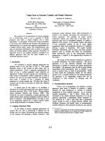
The main components of the SCR system basically are composed of a reactor with the
catalyst, an ammonia storage and injection system and a control system. Figure 1
shows the typical Process Flow Diagram of an SCR system. T
he abatement of nitrogen
oxides results from injection of ammonia into the gas and subsequent passage through
the catalyst, forming elemental nitrogen and water. Ammonia is injected into the gas at
slightly above the molar equivalent ratio as its NOx concentration. The ammonia
injection rate is automatically controlled by combining feed-forward control based on
amount of NOx to the SCR DeNOx unit and feedback control measuring outlet NOx
downstream of the catalyst.
Information contained herein is confidential; it may not be used for any
purpose other than for which it has been issued, and may not be used by
or disclosed to third parties without written approval of Haldor Topsøe A/S.
Combating NOx from refinery sources using SCR Page 6 of 31
N
Ox containing gas
Dilution air
Blower
FT
FT
PC
N
Ox inlet
signal
FV
N
H
3
N
H
3
Evaporator
N
Ox outlet
signal
Gas flow
rate signal
Cleaned gas
SCR
reactor
FT
PC
N
H
3
Figure 1
Basic flow diagram for an SCR DeNOx System
The ammonia reducing agent can be either anhydrous ammonia under pressure or it
can be an aqueous ammonia solution (typically 25% by weight) at atmospheric
pressure. A 30-40% solution of urea which decomposes into ammonia and CO
2
at high
temperature can also be used if warranted by safety. The ammonia is evaporated in a
heated evaporator and is subsequently diluted with air before it is injected into the flue
gas duct upstream the SCR reactor.
The SCR process requires precise control of the ammonia injection rate. Insufficient
injection results in low conversion of NOx and an injection rate which is too high results
in an undesirable release of unconverted ammonia to the atmosphere referred to as
ammonia slip. In the flue gas duct, before the reactor, the NOx mass flow rate will vary
across the cross section area. A homogeneous distribution of the ammonia in the flue
gas is of crucial importance to achieve efficient NOx conversion. The injection of the
ammonia-air mixture therefore may take place through a grid of nozzles in order to
achieve a uniform mixing of the ammonia with the flue gas or via a set of injection
lances located in the turbulent zones immediately downstream vortex creating discs
such as Topsøe’s patented STARMIXER
®
system placed in the flue gas duct (see
section Design considerations on page 27).
Information contained herein is confidential; it may not be used for any
purpose other than for which it has been issued, and may not be used by
or disclosed to third parties without written approval of Haldor Topsøe A/S.
Combating NOx from refinery sources using SCR Page 7 of 31
Information contained herein is confidential; it may not be used for any
purpose other than for which it has been issued, and may not be used by
or disclosed to third parties without written approval of Haldor Topsøe A/S.
Use of gas-flow modelling by Computational Fluid Dynamics (CFD) or in physical scale
models has proven an efficient and often necessary tool to accomplish the goals of
optimum design of a mixing system for completeness of the chemical reactions, as well
as minimum ducting and an attractive plant layout. The general objectives of the model
work are to ensure a high degree of velocity uniformity upstream the ammonia injection
and at the entrance to the catalyst layers and to verify proper mixing of ammonia into
the flue gas. The model work further assists in optimising the lay-out of ducts, reactor
and necessary flow control devices to minimise overall pressure loss.
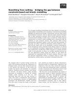
3.2 The SCR catalyst
The commonly applied catalysts are all based on a porous titanium-dioxide carrier
material on which the catalytically active components in the form of vanadium
pentoxide combined with tungsten- and/or molybdenum oxides are dispersed. To cater
for a large gas contact area with a minimum pressure loss, the catalysts are provided
as corrugated or extruded elements containing a large number of parallel channels
(Figure 2) or as elements with a stack of spaced, coated wire-mesh sheets.
Figure 2
The SCR DeNOx reactor and catalyst
The monolithic SCR catalyst elements are assembled into modules for easy
installation. Ammonia is injected in a grid in the flue gas duct upstream the catalyst
NH
3
injection
NO
x
containing gas
Combating NOx from refinery sources using SCR Page 8 of 31
Information contained herein is confidential; it may not be used for any
purpose other than for which it has been issued, and may not be used by
or disclosed to third parties without written approval of Haldor Topsøe A/S.
Each type of catalyst is offered in a number of different models with varying channel
size (often referred to as pitch), wall thickness and with varying chemical composition
adapted to specific operating conditions. The choice of pitch and wall thickness for a
given SCR installation is determined mainly by the concentration and properties of the
dust in flue gas. For low-dust applications, channel sizes of up to approximately 5 mm
are selected. Larger-channel catalysts (6-10 mm pitch) should be selected for
operation in dust-laden gases in SCR units on e.g. Fluid Catalytic Cracking (FCC) units
in which FCC catalyst fines are carried over from the regenerator.
L: Wave length
t: Wall thickness
P
c
: Channel pitch
P
p
: Plate pitch
L t P
c
P
p
DNX-939
1
8.1 0.4 4.1 4.1
DNX-958
2
14.4 0.8 7.2 6.8
1) Catalyst type for heaters, reformers etc.
2) Catalyst type for FCC units
Figure 3
Geometry of Topsøe corrugated DNX
®
catalyst
The required catalyst volume and thereby the size of the SCR reactor depends, of
course, on the NOx concentration in the flue gas and the desired NOx reduction
efficiency but specific operating conditions, e.g. temperature and flue gas dust content,
and the selected catalyst model adapted to these conditions also have a large
influence.
In order to optimise reaction conditions and catalyst replacement strategy, the total
catalyst volume necessary usually is distributed on several layers. Typically, an empty
spare layer is included for addition of catalyst. Addition of catalyst instead of immediate
replacement results in a better utilisation of the remaining catalyst activity prior to a
final replacement.
If the flue gas contains any sulphur dioxide, SO
2
, the active component in the SCR
catalyst, vanadium pentoxide, catalyses a typical ½-1% oxidation of SO
2
to SO
3
.
Downstream the SCR, SO
3
in the flue gas can react with the ammonia slip to form
ammonium bisulphate (ABS, NH
4
HSO
4
) which can cause fouling and corrosion of
equipment. Depending on SCR temperature, ABS may deposit in the catalyst,
eventually blocking the access to its active sites and rendering it inactive. Furthermore,
Combating NOx from refinery sources using SCR Page 9 of 31
the formation of sulphuric acid mist from reaction of SO
3
with water vapour can give
rise to the formation of a visible, blue plume in the stack.
Obviously, the amount of SO
3
formed over the catalyst should therefore be minimised.
Each catalyst producer has his way of balancing the NOx-reduction and the SO
2
-
oxidation activities of the catalyst. A high porosity of the catalyst helps minimise the
SO
2
-oxidation by providing a high fraction of SCR-active surface vanadium sites.
Figure 4 shows the high pore volume of Topsøe’s DNX
®
-type SCR catalyst in
comparison with extruded-types SCR catalysts. The high porosity of DNX
®
is achieved
via a unique tri-modal pore structure, i.e. a pore structure featuring pores in three size
regimes. Extruded-type catalysts typically obtain the pore volume from a micro-porous
structure within a narrow size range.
200
400
600
800
10
100 1,000 10,000 100,000
Pore radius, Å
Extruded catalyst
Topsøe DNX
®
catalyst
Cumulative pore volume (ml/kg)
Figure 4
Pore volume in extruded SCR DeNOx catalyst and Topsøe’s DNX
®
catalyst. The pore volume of the DNX
®
catalyst is roughly twice that of
extruded catalyst types. The high porosity is achieved from pores in
three size regimes, catering to a high resistance towards poisoning
The conversion of NOx on the catalyst takes place on both the inner and outer surface
of the catalyst. As the outer surface fouls with foreign substances deposited from the
flue gas, maintaining access to the interior becomes increasingly important. Large-size
pores, macro-pores, serve to ensure this access to the active interior even if large
amounts of poisons have been deposited on the catalyst as illustrated in Figure 5. The
macro-pores further en
hance gas-phase diffusion of NOx and ammonia into the
catalyst and thereby the overall activity.
Information contained herein is confidential; it may not be used for any
purpose other than for which it has been issued, and may not be used by
or disclosed to third parties without written approval of Haldor Topsøe A/S.
Combating NOx from refinery sources using SCR Page 10 of 31
Flue
g
as
NO
N
2
NO
NO
Homogeneous pore system
Tri-modal pore system
Macro-pore
Meso-pore
Micro-pores
Micro-pore
Chromium
Figure 5
The tri-modal pore system of Topsøe’s DNX
®
catalyst (right) provides
a high resistance towards poisoning from e.g. chromium as the
presence of macro-and meso-pores ensures access to active sites
4 Refinery SCR applications
Many refineries in the U.S. and Europe are facing large NOx emissions reductions over
the next few years. After assembling a list of NOx-emitting equipment, a refiner and its
contractors should review their options, taking into account the technology, catalyst
availability, capital costs, and budget. Refiners have found it necessary to install SCRs
in many of the large heaters, hydrotreaters, catalytic reformers, thermal crackers,
fractionators, and utility boilers, cogeneration equipment, and FCC regenerators.
4.1 SCR for steam cracking and reformer furnaces
Ethylene is produced by steam cracking processes where a hydrocarbon feedstock
reacts with steam in a high temperature environment (700°C ~ 1,100°C; 1,300°F ~
2,000°F). The reaction is highly endothermic and is carried out in relatively small-
diameter (2-15 cm, 1-6 inches) closely arranged reaction tubes.
Steam methane reforming is used in the production of hydrogen from a hydrocarbon
feed, usually natural gas by reacting methane with steam across a catalyst in heated
Information contained herein is confidential; it may not be used for any
purpose other than for which it has been issued, and may not be used by
or disclosed to third parties without written approval of Haldor Topsøe A/S.
Combating NOx from refinery sources using SCR Page 11 of 31
high-alloy tubes which operates at high temperature by direct heat exchange with the
integral furnace that surrounds the reactor tubes.
The tubes in the ethylene cracker’s firebox section are constructed from chromium-
nickel alloys containing 25%-35% Cr and heated by gas- or oil-fired burners. At these
temperatures, chromium in the radiant coil is released into the flue gas. Chromium is
evaporated predominantly as chromium oxyhydroxide (CrO
2
(OH)
2
), which accumulates
in downstream SCR catalyst installations and has a negative impact on catalyst
lifetime. The release of chromium from furnace tubes is seen in all heated high-
temperature cracking and reformer processes.
4.1.1 Chromium deactivation mechanism
Gindorf et al.
5
made experimental measurements of chromium oxide vapour pressures
in humid air at high temperatures. It is likely that CrO
3
and CrO
2
(OH)
2
are the dominant
chromium vapour species in equilibrium with solid Cr
2
O
3
and oxygen rich atmospheres
in dry and wet gas respectively.
At wet flue gas conditions chromium is evaporated according to:
Cr
2
O
3
(s) + 2 H
2
O + 1.5 O
2
→ 2 CrO
2
(OH)
2
(g)
The observed Cr accumulation is 200-2,000 ppmw per 1,000 hours in the first catalyst
layer and in catalyst test coupons installed above the first layer. This is in fair
agreement with the prediction of Cr accumulation on the basis of the thermodynamic
data: At a partial pressure of chromium at 750°C (1382°F) of 0.012 atm, the chromium
uptake in the catalyst would be approximately 900 ppmw Cr per 1,000 hours at a space
velocity 10,000 Nm
3
/m
3
catalyst per hour, assuming 100% retention.
DNX
®
catalyst test coupons have been inserted in a number of ethylene cracking and
steam methane reformer furnace installations in order to monitor the effect of
accumulation of chromium.
The general effect of chromium on the catalyst is a decrease in activity at 350°C
(662°F) that amounts to around 2.6% of the initial activity per 0.1% by weight chromium
accumulated in the catalyst (Figure 6). At a US Gulf Coast ethylene cracking plant
(Plant A) the effect of chr
omium was higher than average during a first run but was at
the same level as found in the other installations during a second run. While there is a
correlation between accumulated chromium and activity, there is no direct correlation
between service hours and activity cf. Figure 7, which means that the chromium uptake
Information contained herein is confidential; it may not be used for any
purpose other than for which it has been issued, and may not be used by
or disclosed to third parties without written approval of Haldor Topsøe A/S.
Combating NOx from refinery sources using SCR Page 12 of 31
Information contained herein is confidential; it may not be used for any
purpose other than for which it has been issued, and may not be used by
or disclosed to third parties without written approval of Haldor Topsøe A/S.
in the catalyst is plant specific. On average, the uptake is ~1 wt% of chromium per
10,000 hours.
0%
20%
40%
60%
80%
100%
0.0 0.2 0.4 0.6 0.8 1.0 1.2 1.4 1.6 1.8
Catalyst chromium content, % by weight
Relative catalyst activity at 350°C/662°F
Plant A, coupon
Plant B, coupon
Plant C, coupon
Plant D, core sample
Plant E, monolith
Plant F, coupon
Plant G, coupon
Plant H, coupon
Plant I, coupon
Plant A, monolith
Plant A, 2nd test
Figure 6
Catalyst activity relative to fresh catalyst activity at 350°C (662°F) versus chromium
accumulation in SCRs on ethylene cracking furnaces and steam methane reformers
0%
20%
40%
60%
80%
100%
0 5,000 10,000 15,000 20,000 25,000 30,000
Service hours
Relative catalyst activity at 350°C/662°F
Figure 7
SCR catalyst activity relative to fresh catalyst activity versus service hours in SCRs
on ethylene cracking furnaces and steam methane reformers
0.0
0.5
1.0
1.5
2.0
2.5
3.0
3.5
4.0
4.5
0 5,000 10,000 15,000 20,000 25,000 30,000 35,000
Service hours
Chromium content, % by weight
Combating NOx from refinery sources using SCR Page 13 of 31
Two full-size catalyst elements were taken from the same SCR unit (Plant A) after
13,000 service hours. The deactivating effect of chromium uptake on the catalyst was
at the same level as found from the test coupons. In the first layer catalyst, having an
average chromium content of 6,000 ppmw, a 4.0% decrease of initial activity at 350°C
(662°F) per 1,000 ppmw Cr was found. Table 1 gives an overview of the results.
“Position” re
fers to the distance from the catalyst element leading edge of the sample.
Chemical composition
(ppm by weight)
k/k
0
Ratio between NH
3
and NOx
reacted
Catalyst
layer No.
Position
mm
Cr K Na
250°C
482°F
350°C
662°F
450°C
842°F
50 14,300 270 1,820
0.49
1.07
0.76
1.09
0.25
1.80
250 3,100 175 1,460
1
450 815 175 1,390
50 710 295 1,630
0.63
1.05
0.85
1.03
0.69
1.17
250 245 230 1,390
2
450 160 230 1,340
Reference <100 ~200 ~800
Table 1
Accumulation of poisons and activity relative to fresh catalyst activity, k/k
0
, after
13,000 service hours at a US Gulf Coast ethylene cracking furnace.
The activity is measured at NOx
inlet
= 500 ppm, NH
3
/NOx ratio = 1.2, 18% O
2
, 3%
H
2
O, 500 mm catalyst element length and space velocity = 20.69 Nm
3
/m
2
/h
The gradient of chromium in the SCR reactor, showing significantly more accumulation
in the first catalyst layer and especially at the inlet face of the catalyst, indicates that
chromium is deposited as extremely fine aerosols with high diffusivity. This also results
in significant overall capture in the SCR catalyst with more than 90% of the chromium
being accumulated in the first catalyst layer. Presumably the chromium is present as
sub-cooled gas-phase monomers that precipitate at the catalyst surface. The
accumulation of other catalyst poisons such as sodium and potassium is very low. The
effect on activity at 350°C (662°F) corresponds to a logarithmic deactivation rate of
19% and 12% per 10,000 hrs in the first and the second layer, respectively.
Deactivation rates between 21% and 35% per 10,000 operating hours after three years
of operation have been reported with other types of SCR DeNOx catalysts
4
.
Information contained herein is confidential; it may not be used for any
purpose other than for which it has been issued, and may not be used by
or disclosed to third parties without written approval of Haldor Topsøe A/S.
Combating NOx from refinery sources using SCR Page 14 of 31
The catalyst deactivation is lowest at 350°C (662°F) and more pronounced at lower
and higher temperature. Usually blinded catalysts with an increased diffusion barrier
show the highest deactivation at the medium temperature. The behaviour of the
chromium-poisoned SCR catalyst is a result of the catalytic properties of chromium
oxide. Chromium oxide is known to have good SCR DeNOx activity in the range of
300-350°C (572-662°F) but also with a significant ammonia oxidation activity above
250°C (662°F)
5
. The oxidation of ammonia is clearly seen from the ratio between NH
3
and NOx reacted. As appears from Table 1 the ratio is significantly higher than 1 at
450°C (842°F). At 250°C (482°F), chromium does
not contribute to the DeNOx activity
to an appreciable extent and observed activity is lower. The optimum temperature
range for the SCR operation is therefore around 350°C (662°F) taking both initial
activity and catalyst deactivation into account.
4.2 SCR DeNOx in fluid catalytic cracking units (FCCU)
One of the largest NOx emissions sources in a refinery is the regenerator of the fluid
catalytic cracking (FCC) unit. FCC is the most important process in a petroleum
refinery and is used to convert high-molecular weight hydrocarbons in the crude oil to
high-octane gasoline and fuel oils. FCC catalysts are fine powders with crystalline
zeolite being the primary active component. The FCC unit consists of the catalyst riser
in which the hydrocarbons are vaporised and cracked by contact with the hot catalyst
recirculated from the regenerator. The mixture of catalyst and hydrocarbon flows
upward to the reactor where the hydrocarbons are separated from the catalyst, which
has deactivated from depositing of carbonaceous material, coke. The catalyst is
returned to the regenerator where it is regenerated by burning off the coke with air
blown into the regenerator. NOx is produced in the regenerator from burning of
nitrogen contained in the coke. The FCCU flue gas NOx concentration typically ranges
from 50 ppmvd to 400 ppmvd with an average of approximately 200 ppmvd.
4.2.1 SCR design issues
Haldor Topsøe’s design philosophy for FCCU SCR applications calls for a vertical
down flow unit. This takes advantage of gravity to address the catalyst fines entrained
in the flue gas. Turning vanes are required to prevent uneven stratification of the solids
and ensure a uniform velocity profile leading at the inlet face of the SCR catalyst.
The most economical place for an SCR installation in an FCC unit is upstream of the
convection section and the design of an SCR thus presents some challenges:
Two-phase flow as the FCC catalyst fines are entrained in the flue gas
The flue gas contains significant amounts of sulphur oxides, SO
2
and SO
3
Information contained herein is confidential; it may not be used for any
purpose other than for which it has been issued, and may not be used by
or disclosed to third parties without written approval of Haldor Topsøe A/S.
Combating NOx from refinery sources using SCR Page 15 of 31
The experience with SCRs in flue gas from FCC units in a “high dust” and high sulphur
service is limited but the experience with SCRs from coal-fired power stations is
extensive. Even though the dust level in the FCC flue gas is fairly high, it is low
compared to the ash content in flue gas from coal-fired power stations. Typical dust
loadings in an FCC unit are 10 to 100 kg/hr compared to 10,000 kg/hr in coal fired
power stations with the same flue gas flow.
The FCC catalyst entrained in the flue gas is typically fines having an average particle
size below 10 microns as well as full range catalyst with an average particle size of 70
microns during an upset. Compared to the fly ash from a coal-fired power station the
FCC catalyst fines have a higher fraction of very fine particles around 1 micron but
otherwise the two types of dust are comparable. Figure 8 shows the particle size
distribution
of FCC fines taken from an electrostatic precipitator (ESP) and two typical
types of fly ash from coal-fired power stations.
0
0,2
0,4
0,6
0,8
1
0,01 0,1 1 10 100 1000 10000
Particle diameter
d
p
[10
-6
m]
d(v/V)/d(log(d
p
))
Bituminous-ash
PRB-ash
FCC-fines
Figure 8
Particle-size distribution of FCC fines in the flue gas from an FCCU
regenerator compared with two types of coal fly ash
4.2.2 ABS condensation considerations
The flue gas from the FCC regenerator contains significant amounts of sulphur dioxide
and sulphur trioxide. With sulphur trioxide present in the flue gas it is necessary to
operate above the temperature for formation of ammonium bisulphate (ABS, NH
4
HSO
4
)
from reaction of the injected ammonia with sulphur trioxide:
Information contained herein is confidential; it may not be used for any
purpose other than for which it has been issued, and may not be used by
or disclosed to third parties without written approval of Haldor Topsøe A/S.
Combating NOx from refinery sources using SCR Page 16 of 31
NH
3
+ SO
3
+ H
2
O → NH
4
HSO
4
(l)
Liquid ABS formation is a function of temperature, ammonia partial pressure and SO
3
partial pressure. The bulk condensation temperature in the SCR reactor inlet is typically
in the range 270-300°C (520-570°F) but the condensation will occur at a 20-30°C (35-
85°F) higher temperatures in the catalyst due to capillary forces in the micro-porous
structure of the catalyst. The consequence of condensation of ABS in the pores of the
catalyst is that activity becomes reduced as access to the active sites becomes
blocked. However, ABS is a temporary foulant as the condensation process is
reversible and raising the operating temperature back above the dew point will cause
the ABS to evaporate and catalyst activity be restored.
The catalyst ABS dew point temperature as a function of SO
3
concentration is shown in
Figure 9 for different inlet NH
3
concentrations. The NH
3
concentration at the inlet to the
SCR is around 1.25 times the NOx concentration for a desired NOx removal efficiency
of 80%.
240
250
260
270
280
290
300
310
320
330
0.1 1 10 100
SO
3
, mg/Nm
3
ABS dew point, °C
400 ppm
200 ppm
100 ppm
50 ppm
NH
3
concentration
Figure 9
The temperature for ABS condensation in the catalyst as a function of SO
3
concentration for different ammonia concentrations
Information contained herein is confidential; it may not be used for any
purpose other than for which it has been issued, and may not be used by
or disclosed to third parties without written approval of Haldor Topsøe A/S.
Combating NOx from refinery sources using SCR Page 17 of 31
4.2.3 Catalyst selection
The SCR catalyst to be selected must be designed to perform reliably in the FCC unit’s
erosive environment. This catalyst should have a thick robust wall and a wide pitch to
avoid plugging of the catalyst channels with FCC catalyst fines entrained in the flue
gas. To ensure a low pressure drop across the catalyst layers, a catalyst with an
approximately 7-mm pitch and a wall thickness of minimum 0.8 mm is selected as
shown in Figure 3.
The Haldor Topsøe DNX
®
catalyst utilises a tri-modal pore size distribution containing
macro- pores, meso-pores and micro pores for activity retention in this dust laden
environment as described in Figure 5. The fines are able to fill the macro-pores. At
some point, the macro pores accept
the maximum amount of catalyst dust, yet NOx
and NH
3
in the flue gas can still diffuse into these pores through the remaining void
space and complete the reduction reaction on the active sites of the catalyst surface.
4.2.4 Catalyst cleaning
Even though a wide-pitch catalyst is selected, provisions for regular cleaning of the
catalyst must be taken. The FCC catalyst fines carried to the SCR reactor are of a
sticky nature, partly because of the small particle size, and tend to build up on the top
grid wire mesh covering the catalyst modules and on the leading edge of the catalyst
channels (see e.g. Figure 18 on page 26).
Rake-type soot blowers
using superheated steam or compressed are recommended
for this cleaning purpose. They will typically have to be operated 1-3 times per day.
5 Industrial experience
5.1 Chevron Phillips, Cedar Bayou, Texas, USA (ethylene plant)
Several (13 out of 14) ethylene cracking furnaces were revamped to add SCR reactors.
This project required the addition of new convection sections containing the SCR
reactor. New steam super heater coils were added to the scope of the project to
achieve greater thermal efficiency. Plot space is limited and forced the new equipment
to be placed on top of the existing heater. This increased the overall height of the
heaters by approximately 6 meters (20 feet), cf. Figure 10.
Information contained herein is confidential; it may not be used for any
purpose other than for which it has been issued, and may not be used by
or disclosed to third parties without written approval of Haldor Topsøe A/S.
Combating NOx from refinery sources using SCR Page 18 of 31
Figure 10
Additional convection sections placed on top of the existing heater of
the ethylene plant at Chevron Phillips, Cedar Bayou, Texas, USA
The ammonia injection grid (AIG) is located less than 3 m (10 ft) from the inlet face of
the SCR catalyst. This provides only short mixing time and mixing distance for the
ammonia to blend in with the flue gas. Thus, a bank of convection coils was placed
between the AIG and the SCR catalyst to facilitate mixing and achieve optimum SCR
reaction temperature (Figure 11).
Figure 11
Left: CFD grid of ammonia injection grid, convection section and SCR
Right: Installation of SCR
Information contained herein is confidential; it may not be used for any
purpose other than for which it has been issued, and may not be used by
or disclosed to third parties without written approval of Haldor Topsøe A/S.
Combating NOx from refinery sources using SCR Page 19 of 31
Additional convection coils were located upstream of the stack to recover more latent
heat. Prior to the turnaround project to integrate SCR into the ethylene furnaces, the
outlet stack temperatures were typically around 260°C (500°F). After the revamp, the
new convection sections reduced stack heat leaks and outlet stack temperatures are
below 150°C (300°F).
5.1.1 NOx reduction performance
The first of the cracking furnace SCR units was placed on line in September 2003 and
was given a three year service life guarantee. Figure 12 shows the catalytic
performance to be excellent well be
yond the service life even in this challenging
application where chromium poisoning is present. The graph clearly shows that outlet
NOx and NH
3
slip can easily be controlled below 10 ppmv more than four years after
initial start-up of the SCR unit.
Figure 12
Ethylene cracking furnace SCR performance
5.1.2 Chromium accumulation in the catalyst
Figure 13 shows the chromium and the vanadium profile through a DNX
®
catalyst after
13,000 hrs in the SCR (same catalyst as the Layer 1 catalyst in Table 1 page 13). The
profile is o
btained by wavelength dispersive spectroscopy (WDS) in a scanning
Information contained herein is confidential; it may not be used for any
purpose other than for which it has been issued, and may not be used by
or disclosed to third parties without written approval of Haldor Topsøe A/S.
Combating NOx from refinery sources using SCR Page 20 of 31
electron microscope (SEM). WDS provides a quantitative measurement of the element
concentrations. The SEM image to the right shows where the profile was acquired.
Chromium is not a traditional blinding agent but acts as a masking agent, which, as
mentioned earlier, also has an effect on catalytic behaviour. The chromium has
accumulated primarily at the catalyst surface with up to 9% by weight but chromium
also exhibits some surface diffusion mobility and diffuses into the catalyst matrix. The
thin chromium layer on the catalyst surface is visible on the wall cross section picture.
Furthermore, it is seen that the deposits are visible three to four pore diameters or 50
μm into the pore mouth of the macro pores of the catalyst. This deposition pattern is
typical for extremely fine aerosols or sub-cooled gas-phase monomers that diffuse into
the macro pores and stick to the surface.
To maintain sufficient catalyst activity at this poison deposition pattern, the presence of
a diverse pore structure is important as illustrated in Figure 5. The activity of the
cataly
st shown in Figure 13 is 76% of fresh catalyst activity at 350°C (662°F).
0
2
4
6
8
10
0 50 100 150 200 250 300
Distance (µm)
Weight-%
Cr
V
Figure 13
Vanadium and chromium profile through the catalyst wall after 13,000 service
hours at Cedar Bayou layer 1. The profile is obtained by WDS in a scanning
electron microscope (SEM). The SEM image to the right shows where the
profile was acquired.
Figure 14 shows a close up picture of the catalyst wall cross section. The thickness of
the chromium deposits is just 1 - 2 μm. The surface picture
s of the fouling layer show
the fine chromium oxide particles. The surface is not completely closed and reactants
are still allowed to diffuse into the catalyst pore system. For comparison, a surface
picture of the cleaner catalyst from the second layer is presented.
Information contained herein is confidential; it may not be used for any
purpose other than for which it has been issued, and may not be used by
or disclosed to third parties without written approval of Haldor Topsøe A/S.
Combating NOx from refinery sources using SCR Page 21 of 31
Information contained herein is confidential; it may not be used for any
purpose other than for which it has been issued, and may not be used by
or disclosed to third parties without written approval of Haldor Topsøe A/S.
Figure 14
Wall cross section and surface pictures of chromium deposits on first and second
layer catalyst at Cedar Bayou after 13,000 hrs
Extracted catalyst samples were analysed for possible presence of toxic hexavalent
chromium(VI) species but none were found.
5.2 Fluid catalytic cracking units
In the following design considerations and experience from two Topsøe installations of
SCR’s after FCC units are presented: 1) Shell, Deer Park Refinery, Texas, USA and 2)
CITGO Petroleum; Lemont Refinery, Illinois, USA. These experiences are further
detailed in papers presented at National Petrochemical & Refiners Association’s annual
meetings in 2005
2
and 2010
3
.
5.3 Shell, Deer Park Refinery, Texas, USA
In the Shell Deer Park catalytic cracker, flue gas from the catalyst regenerator first
passes through a third (3rd) stage separator to knock out catalyst particles and then it
flows to the expander which is used to recover power to drive the main air blower.
There is no ESP in this unit. From the expander outlet, the flue gas enters the CO
combustor to oxidise the CO to CO
2
. Hot flue gas from the CO combustor flows to the
catalytic cracker feed preheater box via four transition ducts.
Performance requirements imposed by EPA for outlet NOx were:
- 20 ppmvd on a 365-day average at 0% reference oxygen
- 40 ppmvd on a 3-hour average at 0% reference oxygen
The SCR catalyst was guaranteed to remove 90% over a 5-year run-span which put
the refinery right at the maximum limit of 20 ppm outlet NOx with 200 ppm Inlet NOx.
Catalyst surface 1. layer Catalyst surface 2. layerCatalyst cross section
Combating NOx from refinery sources using SCR Page 22 of 31
Based on this, the refinery decided to use both SNCR and SCR to achieve the final
results.
Figure 15
Catalyst cracker flue gas flow path at Shell, Deer Park Refinery, Texas, USA
Ammonia injection facilities were added to each duct to implement the SNCR
technology. Flue gas from the oil box passes through another box containing coils for
steam production steam superheating. Flue gas from the steam box flows to the SCR.
The flue gas temperature to the SCR is controlled by bypassing BFW around the
preheater coil. The SCR is designed for down flow with two catalyst layers with a
provision to add a third layer. From the SCR the flue gas is routed to the caustic
scrubber for desulphurisation before exiting the 60 m high stack.
Key issues in the SCR design were:
- High SO
2
content of flue gas 1000+ ppmvd
- High solids loading – 40-50 lbs/hr (18-23 kg/h) normal, 200 lbs/hr (91 kg/h)
maximum as there is no ESP in front of SCR
- SO
3
content 3-12 ppmvd
Available flue gas temperature was limited to about 288°C (550°F)
All the CEMS (Continuous Emission Monitoring System) analysers are in the stack.
There are NOx, SOx and opacity analysers in the duct before the SCR for checking the
process performance. The SCR is also equipped with a bypass duct which is to be
used in case of high pressure in the CO combustor or loss of activity of SCR catalyst.
Bypass can also be used in case of excessive carryover of solids as determined by the
Information contained herein is confidential; it may not be used for any
purpose other than for which it has been issued, and may not be used by
or disclosed to third parties without written approval of Haldor Topsøe A/S.
Combating NOx from refinery sources using SCR Page 23 of 31
opacity readings in the duct and high pressure drop in the SCR as a result of plugging
with solids.
5.3.1 ABS considerations
The high SO
3
content of the flue gas, 3-13 ppmvd, 11-39 mg/Nm
3
, represented a
challenge to the SCR design, necessitating an operating temperature above 290-305°C
(554-581°F) to avoid ABS condensation in the SCR catalyst, cf. Figure 9 on page 16.
The ideal te
mperature for the SCR would have been above 700°F. This could have
been accomplished by splitting the steam convection section; however, there was
neither time nor space available to implement this idea. Another option was to place
the SCR downstream of the FGD and hereby reduce the SO
3
content; however, the
cost of reheating the flue gas made it prohibitive. The SCR was therefore chosen to be
installed in between the steam convection section and the FGD, the advantage being
that the tie-ins could be completed during the 2002 turnaround. The temperature at this
point can be controlled between 260°C and 315°C (500-600°F), but there is a risk of
ABS formation. The ABS formation is reversible; and in case of ABS formation on the
catalyst, the inlet temperature will be elevated to 315+°C (600+°F) which is sufficient to
sublime the salts. This is done with a bypass on the boiler feed water to the convection
section.
5.3.2 Ammonia mixing and SCR lay-out
Shell Deer Park decided to use 19% aqueous ammonia as there are no restrictions on
the quantity that can be stored. The aqueous ammonia is vaporised in kettle type
electric exchangers. Ammonia dilution air is also heated using electric heaters.
For the Shell Deer Park FCC, 19% aqueous ammonia was selected as the ammonia
source. The aqueous ammonia is vaporised before it is injected into the flue gas. To
ensure a sufficient mixing of the ammonia and the flue gas, the point of injection of the
ammonia into the flue gas must be as far away from the catalyst as possible. A proper
location must be determined based on mixing and temperature. Proper mixing is even
more critical when increased NOx conversion rates are required, and in a hybrid
system with a combination of SNCR and SCR, there is a risk of having an uneven
NH
3
/NOx distribution at the entrance to the reactor. Ammonia injection is done through
an injection grid containing several nozzles. For this SCR a static mixer, turning vanes,
and a flow rectifier were required.
Furthermore, the plot space available made it impossible to have a more typical direct
entry into the SCR reactor. After many trials, a solution was developed which required
a 90° turn into the AIG and two static mixers followed by a 180° turn and drop into the
main body of the SCR.
Information contained herein is confidential; it may not be used for any
purpose other than for which it has been issued, and may not be used by
or disclosed to third parties without written approval of Haldor Topsøe A/S.
Combating NOx from refinery sources using SCR Page 24 of 31
A 1:12 scale model, Figure 16, was constructed based on the results of the CFD
modelling and interactio
n with the engineering design company for space availability.
The advantage of the physical model is its ability to simulate two phase flow. Dust
accumulation was modelled in various areas of the duct-work and the SCR using a
suitable powder to represent the FCCU fines at the test conditions.
Figure 16
1:12 scale model and 3D drawing of the SCR at Shell, Deer Park Refinery
Dust accumulation tests were carried out at different dust loads corresponding to
normal operation and a simulation of a major FCCU catalyst carry-over.
The use of the physical model greatly assisted in the determination of the position and
shape of the turning vanes, mixers and the AIG. Sulzer supplied the scale model mixer
and AIG components for the test as well as the full-sized components for the project.
5.3.3 Performance
The SCR for the Shell Deer Park FCCU was commissioned in the fall of 2004. The unit
was built with the FCCU in operation and started up within schedule. When the unit
came online it performed immediately; no tuning was necessary because of the way
the SCR is designed. The pressure drop over the SCR is constant and lower than the
guarantee. The NOx reduction has been higher than the guarantee. Since it is start of
run for the catalyst It has been possible to bring the outlet NOx down to much lower
numbers than the guarantee of 20 ppmvd. The outlet NOx is consistently controlled
lower than 20 ppmvd, and the SNCR has therefore not been put in service. The inlet
temperature to the SCR has been maintained between 525°F and 550°F (275-288°C).
Information contained herein is confidential; it may not be used for any
purpose other than for which it has been issued, and may not be used by
or disclosed to third parties without written approval of Haldor Topsøe A/S.
Combating NOx from refinery sources using SCR Page 25 of 31
There has not been any measurable ammonia slip in the stack, which is not a surprise
since it is downstream of the FGD. However, we have not found any measurable
ammonia increase in the waste water from the FGD.
NOx Reduction
0
50
10 0
15 0
200
250
20-09-2004 29-12-2004 08-04-2005 17-07-2005 25-10-2005 02-02-2006 13-05-2006
date
Inlet NOx Outlet NOx Nox Guarantee
Figure 17
The outlet NOx level at the Shell Deer Park Refinery well below guarantee
5.3.4 Catalyst cleaning
Sonic horns were initially selected for this project. Sonic horns can be operated at any
defined interval of time, cost less than traditional soot-blowers and are more easily
maintained.
However, at several occasions an increased pressure loss across the SCR catalyst
layers was experienced. Inspections revealed a significant build-up of FCC catalyst
fines on the wire mesh covering the catalyst modules. After investigation of the
operating data it was found that the increased pressure drop was caused by operation
at temperatures lower than the ABS condensation temperature for a long period. ABS
should be possible to evaporate but the combination of sticky ABS and FCC fines
apparently made it impossible to evaporate the ABS. Figure 18 shows how the dust
covers the catalyst layer, effectively blocking
the gas passage, and the situation after
vacuum cleaning. It became obvious that the sonic horns were not able to remove the
dust build-ups and it was therefore decided to install steam soot blowers in 2006.
Information contained herein is confidential; it may not be used for any
purpose other than for which it has been issued, and may not be used by
or disclosed to third parties without written approval of Haldor Topsøe A/S.