Báo cáo " Hazard removal solution by synchronization " pdf
Bạn đang xem bản rút gọn của tài liệu. Xem và tải ngay bản đầy đủ của tài liệu tại đây (52.35 KB, 6 trang )
VNU Journal of Science, Mathematics - Physics 25 (2009) 117-122
117
Hazard removal solution by synchronization
Nguyen Quy Thuong
*
Vietnam National University, 144 Xuan Thuy, Cau Giay, Hanoi, Vietnam
Received 25 June 2009; received in revised form 10 July 2009
Abstract. There are many methods to design digital circuits without hazard, such as the use of
Boolean algebra, algebra hazard, karnaugh map, matrix method, VHDL, etc. However, these
methods are not very suitable for the design of circuit system such as design of GALS circuits. In
this case, synchronization is the most optimal method.
1. Introduction
Hazard is the essence of digital circuits including synchronous circuit and asynchronous circuit.
Hazard occurs as much as “autumn’s leaves” [1] and has adverse impact on the working of digital
circuits. However, Hazard only has insignificant impact on synchronous circuit while it can make the
operation of asynchronous circuits incorrect and even stop the operation of machine [2].
In design of digital circuit, Hazard can be removed by many methods and most typical ones
include Karnaugh map, Boolean algebra [3], Hazard algebra [4], Matrix Method [5] and VHDL [6],
etc. However, these methods are not really suitable for the design of such circuit system including both
synchronous circuit and asynchronous circuit as GALS circuit [7] and sequetial circuit. As
synchronous circuits are not significantly subject to the impact of Hazard, we can immediately think of
synchronization of the whole circuit system so as to remove the negative impact of Hazard on
asynchronous circuits in particular and on the whole system in general.
2. Removal of Hazard in asynchronous sequential circuits by synchronization method
In this section, we turn our attention to asynchronous circuits or signals driving synchro-
nous circuits. Initially, we look at the problem that occurs if an asynchronous signal is applied
directly to the synchronous circuit without special treatment. Then we offer a solution but find that
there is an additional problem with the solution, which we also attempt to remedy.
The circuit in Figure 1 can illustrate erroneous behavior due to an input signal not synchronized
with the clock. The circuit is initialized by using the Reset signal which sets the state of the circuit to
S0 (y0, y1, y2 = 1,0,0). As long as RDY = 1, the circuit cycles through the states S0 (1,0,0) and S1
(0,1,0) and S2(0,0,1). If RDY = 0, then the circuit waits in state S0 until RDY = 1 causes it to go to state
S1. Also, the state can change from S1 to S2 and from S2 to S0 with RDY = 0. All other combinations
of state variables are invalid during the normal operation of the circuit.
______
*
E-mail:
N.Q. Thuong / VNU Journal of Science, Mathematics - Physics 25 (2009) 117-122
118
Now suppose that RDY is asynchronous with respect to Clock. This means that it can change any
time during the clock period. In Figure 1, the signal RDY changes well away from the positive clock
edge, so that the setup and hold times for flip-flops y0 and y1 are easily met. The circuit operates
normally. When RDY goes to 0 and the circuit reaches state S0, it waits in state S0 until RDY goes to 1.
At the next positive clock edge, the stage changes to S1. The circuit then proceeds to state S2 and back
to S0.
When y0 resets to 0, but y1 fails to set to 1, giving state (0,0,0). Since there is no 1 to circulate
among the flip-flops, the state remains at (0,0,0). The circuit is locked in this state and has failed.
When y1 sets and y0 fails to reset, giving state (1,1,0). There are now two 1s circulating among the
flip-flops, giving state sequence 110, 011, 101. These are all invalid states and give an incorrect output
sequence. Thus, the circuit has again failed.
Fig. 1. Example Circuit for Illustration of Synchronization.
So a solution is needed to prevent these failures that is independent of these parameters. Such a
solution is the use of a synchronizing flip-flop.
Fig. 2 Circuit with Synchronizing D Flip-flop Added.
In Figure 2, D flip-flop has been added to the example circuit. The asynchronous signal RDY
enters the D flip-flop and RDY_S, its output, is synchronous with signal Clock in the sense that
RDY_S changes one flip-flop delay after the positive edge.
N.Q. Thuong / VNU Journal of Science, Mathematics - Physics 25 (2009) 117-122
119
Since the asynchronous signal RDY enters the circuit through this single synchronizing flip- flop,
the behavior exhibited when RDY reached two flip-flops is avoided. RDY_S cannot cause such
behavior since it does not change during the setup time, hold time interval for the flip-flops.
The behavior discussed in this paragraph is illustrated in Figure 2. The case in which the change in
RDY is immediately sensed by the flip-flop and the case in which RDY is not sensed until the next
positive clock edge are shown. In the latter case, the response to the change in RDY is delayed by an
extra clock period. Since RDY is asynchronous, the fact that the times at which state changes occur
due to changes in RDY may vary by a clock period should be of no consequence. The length of time it
remains in the metastable state is non-deterministic.The interval during which a change in the input
will cause metastable behavior is verynarrow, of the order of a few tens of picoseconds. Thus the
behavior is unlikely, but it can happen. When it does, it is unknown how long the metastable state will
persist. If it does persist for a clock period, then the two flip-flops in our example will see a value on
the synchronizing flip-flop output RDY_S that is between 0 and 1. Response by the two flip-flops to
such a value is unpredictable, so there is a good chance that the circuit will fail.
They had pictures of oscilloscope traces showing the metastable behavior. At about the same time,
Digital Equipment Corporation was experiencinginfrequent, unexplained failures in their new, faster
computers. You can probably guessthe cause! The nature of metastable behavior for a particular
CMOS D flip-flop used asa synchronizing flip-flop is shown in Figure 3; this data was gathered over
30 minutes. The normal delay from the Clock to Q is 13 ns as indicated by the dotted line. But by
carefully controlling the timing of the changes in D and the Clock, the flip-flop is forced into its
metastable region. In that region, the best flip-flop delay seen is 30 ns and the worst is 45 ns. Thus, if
the clock period is less than 45 ns, a metastable event that can adversely affect the behavior of two or
more flip-flops within the circuit being driven by the synchronizing flip-flop occurs many times in 30
minutes. Actually, although not shown in the figure, the changes in Q closer to 30 ns are much more
frequent than those close to 45 ns.
Fig. 3. Metastable Behavior.
So the shorter the clock period the worse the problem gets. If the sampling interval were 50 hours,
there would be a few events appearing as late as 55 ns. The value between 1 and 0 that occurs for a
time inside the flip-flop in this experiment is converted to a longer delay by the output buffer of the
flip-flop and so is not visible at the output.
N.Q. Thuong / VNU Journal of Science, Mathematics - Physics 25 (2009) 117-122
120
So what can be done about this problem? There have been many solutions proposed, some of
which are worthless. A simple one is to use a series of synchronizing flip-flops, i.e., a small shift
register. The likelihood of the second flip-flop in the series going meta- stable because the first one
applies a metastable or delayed input to it is less than the first flip-flop going metastable, etc. Some
commercial designs have used as many as six flip-flops in series to deal with this problem. More
common is the use of two to three flip-flops in series. The more flip-flops, the more the circuit
response to a change is delayed and the less likely the circuit is to fail due to metastability. But the
probability never goes to zero. Some degree of uncertainty of incorrect operation always remains,
however small.
As for synchronizing flip-flops, their use is essential in making the transition from asynchronous
signals to a synchronous circuit. Care must be taken to deal with metastability.
There is a lot more to synchronization than we have presented here. For example, if the timing of a
set of asynchronous signals is known relative to another particular asynchronous signal, only the latter
signal may need to be synchronized. Also, just because our example suggests making an asynchronous
signal enter a circuit through one flip-flop to solve the problem, this does not say in general that a
circuit having only one flip-flop instead of two or more will be free of synchronization problems. A
notable problem is the case where there is combinational logic containing hazards between the
asynchronous signal or signals and the single flip-flop.
In summary, there are certainly situations where you must use asynchronous circuits to get the
desired behavior. But these situations are far fewer than the cases where someone thinks they need an
asynchronous circuit. So try to avoid them whenever you can.
3. Removal of Hazards in GALS circuits
Today demand for high-density chips such as S
0
C
s
(system- on - chip) and N
o
C
s
(network – on -
chip) and the development of CMOS technology always results in complex circuits. Then, the use of
conventional methods becomes difficult. GALS (Global Asynchone – Local Synchrone) architecture is
also part of a complex system. In order to perform a GALS architecture, a system is divided into many
clock independent modules (local - synchro). These modules will be put into one wrapper and be
clear-to-send to each other (global - asynchrone). These GALS circuits will lead to the problem of
designing a compatible hardware. In general, there is no fully automatic design method for GALS
circuits. However, thanks to many great efforts, available methods are improved for a certain objective
by which asynchronous chips will be developed continuously and controlled automatically.
Signals of synchronous machines have phase relation among each other. This leads to the fact that
two wrappers in time – out phase will exist in the design of synchronous GALS circuits. Generation of
tact synchronization will be difficult if external tact signal from asynchronous peripheral areas is
transmitted to the wrapper and if this signal is either stopped or resumes the operation within the
working period of the wrapper. As one may know, quartz tact always works and is defined by Stopi
cotrol signal if the tact needs to be transmitted to the wrapper. Stopi is immediately created when tact
can be received from asynchronous peripheral area. For the adjustment of tact synchronization
process, Stopi and external tact signal shall be established in the mutual relation to each other. If
external tact signal and check signal is linked by one AND port only, the obtained result is shown in
Figure 4
N.Q. Thuong / VNU Journal of Science, Mathematics - Physics 25 (2009) 117-122
121
&
Internal Clock
Stopi
External Clock
Stopi
External Clock
Internal Clock
Haazard
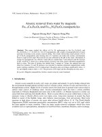
Fig. 4. Tact synchronization using one AND port and from here, signal running process will cause a Glitch.
Failure to have synchronization of external tact signal and Stopi control signal may lead to the
appearance of hazard in logical link, for example, change in Stopi value before external tact signal
reaches a lower level. Therefore, electric circuit will probably exist at the time of switching, which
creates a glitch. Stopi selecting signal is only allowed to change its signal when external tact signal
creates a low level. In order to achieve this target, for example, wrapper component clock control (for
synchronization of tact signal and control signal) must be changed.
Similarly, if tact signal needs to be stopped and allowed freely return during the operation of
wrapper, Glitch may appear.
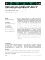
Only a minor change is made in the wrapper component clock control. As mentioned, the
significant change of check signal to the receipt of external tact signal into the wrapper is made
through the reset of a F.F. Then, Stopi is first generated right after external tact signal is equal to a
lower impulse. During clock check, REQ INT signal is directly led to the reset inlet of Flip – Flop, and
additional AND port is included (Figure 5), in which external clock tact signal is led to negative port.
AND port will first create an increased impulse at the output right after external tact signal is at low
level of the inlet of wrapper. Based on the above discussion, hazard can appear at AND port but it
does not cause negative impact on general system as appeared glitches only affect the established
relation of Flip – Flop; therefore, the impact at this position does not play any role in the proper
operation of the system.
Internal Clock
&
&
Q
R D
Counter
Reset
Clock control H
Clock control I
ST
ACK_INT
RST
REQ_INT
Fig. 5. Change clock control an mesochrone GALS - wrappers.
Thus, with a system of digital circuits such as series circuits and GALS circuits, it is possible to
remove errors, glitches and hazards by synchronization of asynchronous signals and synchronous
signals using circuit manipulations which are not very complicated and costly.
N.Q. Thuong / VNU Journal of Science, Mathematics - Physics 25 (2009) 117-122
122
References
[1] John Knight, Asynchronous Circuits Races, Cycles and Effect of Hazards, Electronics Department, Carleton
University, April 1, 2006.
[2] John Knight, Glitches and Hazards in Digital Circuits, Electronics Department, Carleton University, April 1, 2006.
[3] Nguyen Quy Thuong, Digital Technics, Vietnam University Publishing House, Hanoi (in Vietnamese) (2007) 575.
[4] Nguyen Quy Thuong, Hazard Essence - Process, Vietnam University Publishing House, Hanoi (in Vietnamese) (2009)
180.
[5] E.C. Tan, M.H. Ho, Matrix method to detect logic Hazard in combinational cicuits with EX–OR gates. Nanyang
Tachnological University, Singapore
[6] Nguyen Quy Thuong, Race and hazard algebra in asynchronous system, VNU Journal of science, Vol. 24, No. 1 (2008)
47.
[7] Frank Winker, Entwurf und VHDL - modellierung von mesochronen GALS – Schaltungen, Humboldt universitaet zu
Berlin 2006.