HƯỚNG DẪN LẮP ĐẶT VẬN HÀNH MÁY TRUNG TÂM GIA CÔNG CNC
Bạn đang xem bản rút gọn của tài liệu. Xem và tải ngay bản đầy đủ của tài liệu tại đây (13.98 MB, 143 trang )
HƯ NG D N L P Đ T
V N HÀNH MÁY TRUNG
TÂM GIA CÔNG CNC
MODEL:
SERIAL NO.:
QV159
1P01393B7
HELLER MÁQUINAS - HERRAMIENTA, S. L
C/Nicolas de Bussi, 44 03203-ELCHE (Alicante), España
TEL: +34 965 430 014 FAX: +34 965 431 195
E-mail:
HELLER MÁQUINAS - HERRAMIENTA, S. L. All rights reserved.
Edition.:2018 En “Original of instructions”
HELLER MÁQUINAS - HERRAMIENTA, S. L
C/Nicolas de Bussi, 44 03203-ELCHE (Alicante), España
TEL: +34 965 430 014 FAX: +34 965 431 195
E-mail:
Contents
CÁC HƯ NG D N AN TOÀN………........…………………………..……………..…0
QUY Đ NH AN TỒN MÁY...……..……………………………………. ......................1
C nh báo v an tồn khi v n hành máy…….………………………………………………. ....................1.1
C nh báo đ v n hành máy an toàn…………………….………………………………………………..1.2
Tuyên b v ti ng n phát th i...………………….……………………………………………………...1.3
X lý ch t th i …………………………….………………………………………………………....1.4
T
khóa
đi n
t .....….
……………………….………………………………………………………..1.5 Tích h p làm m tr c
chính...……………………………………………………………………………..1.6 Kh i đ ng ngày
phép……………………………………………………………………………………..1.7
THÔNG S
K THU T…………..…………………………………………...………2
H p k thu t…………………………………………………………………………….………………2.1
Ph ki n………………………………………………………………………………….……………2.2
Cách ch n th 4……………………………………………………………………….…………..….2.3
Shank & Pull Stud……………………………………………………………………….……………….2.4
Kích thư c bàn………………………………………………………………………….………………..2.5
Di n tích sàn……………………………………………………………………………….………….….2.6
Vùng ho t đ ng…………………………………………………………………………….……….…..2.7
Kích thư c………………………………………………………………………………………..…..2.8
Danh sách l nh M Code...………………………………………………………………………….…...2.9
Danh sách l nh G Code………...………………………………………………………………………….2.10
Danh sách đ ng cơ xoay chi u tr c chính………………………………………………………….. .….
2.11 Danh sách đ ng cơ servo…………………………………………………………………………...…
2.12
Ki u dây đai tr c chính………………………………………………………………………………. ....2.13
Ki u truy n đ ng tr c ti p tr c chính…………………………………………………………………..2.14
V N CHUY N VÀ L P Đ T……………………………….……...................................3
Các yêu c u v môi trư ng l p đ t máy………………………………………………3.1
Các phòng ng a khi l p đ t………………………………...…………………………………………...3.2
Các chú ý khi v n chuy n, l p đ t…………………..….…………………………………….…3.3
L p đ t……………………………………………………...………………………………………...3.4
Bàn……………………………………………………………...……………………………………….3.5
BÀN ĐI U KHI N HO T Đ NG (MITSUBISHI&FANUC)…………...………...4
Nút kh i đ ng và d ng kh n…………...........…………………………......................…4.1
Nút kh i đ ng và d ng theo chu k ....………………………………………...………………….………….4.2
Đèn tr ng thái và âm thanh………………………………………………………..….………………………4.3
V n hành t đ ng………………………………………………………………...………………..………...4.4
V n hành th công……………………………………………………………...…………..……………...4.5
Các ch c năng khác…………………………………………………………………...………………………4.6
Override Selection Button……………………………………………………...………………………..4.7
Manual Pulse Generator (Handle)……………………………………………………...………………..4.8
Spindle Functions…………………………………………………………………….………………….4.9
Option Functions………………………………………………………………………….………. ......4.10
HELLER MÁQUINAS - HERRAMIENTA, S. L
C/Nicolas de Bussi, 44 03203-ELCHE (Alicante), España
TEL: +34 965 430 014 FAX: +34 965 431 195
E-mail:
MACHINE OPERATION…………………………………………………………….....5
Power ON………………………………………………………………………………………………..5.1
Power OFF………………………………………………………………………………….……………5.2
Reference Point Return…………………………………………………………………….…………….5.3
Jog And Rapid Feed……………………………………………………………………….……………..5.4
HANDLE mode…………………………………………………………………………….……………5.5
Change Tools by Manual…………………………………………………………………….…………..5.6
Clamp and Unclamp.………………………………………………………………………….…………5.7
Chip Conveyor Operation (Option) ………………………………………………………….………….5.8
Data IN/OUT………………………………………………………………………………….………....5.9
PLC SW or OPR PANEL……………………………………………………………………………….5.10
The 4th Operation………………………………………………………………………………………..5.11
Tool Change and Oversize Tool Management (ARM type only) …………………………………...…5.12
Tool Measurement……………………………………………………………………………………....5.13
Work Piece Set………………………………………………………………………………………….5.14
MAINTENANCE................................................................................................................6
Air System………………………………………………………………………………………………..6.1
Slideway Lubricating System…………………………………………………………………………….6.2
Coolant System…………………………………………………………………………………………...6.3
Oil Cooler for Spindle (Option) ……………………………………………………….…………………6.4
Oil Type and Replace Period Time……………………………………………………………………….6.5
Maintenance………………………………………………………………………………………………6.6
Gibs Adjust……………………………………………………… ……………………………………….6.7
TROUBLESHOOTING…………………………………………………………..………7
The Qualification of Maintenance Man…………………………………………………………………..7.1
Machine Restart…………………………………………………………………………………………..7.2
Space Needed for Maintenance…………………………………………………………………………..7.3
When the Tool Number at the Spindle or Magazine Isn´t Your Select…………………………………..7.4
Takeout and Input Tools By Manual……………………………………………………………………..7.5
The Tool Don´t Exchange, When Execute the M6 Code.....……………………………………………..7.6
Tool Changer Does Not Act Continuously……………………………………………………………….7.7
Tool Struck…………………………………………………………….……………………………... ….7.8
Arm Position Incorrect………………………………………………………………………………....…7.9
O.T. Elimination……………………………………………………………………………………...….7.10
Coolant Low…………………………………………………………….…………………………….....7.11
Servo Overload…………………………………………………………….………………………….....7.12
LED Gone Out…………………………………………………………….……………………………..7.13
MESSAGE ALARM PLC……………………………………………………………….8
APPENDIX A OPTION FUNCTION (FANUC)………………………………………9
Programmed Tool Offset Input……………………………………………….…………………………9.1
Linear Angle, Corner Chamfering (C), and Corner Rounding (R)……………………………… ……..9.2
Scaling (G50, G51)……………………………………….……….…………………………………….9.3
Mirror Image (G50.1, G51.1)……..……………………………….…….……………………………...9.4
Helical Interpolation……………………………………………………….…….……………………...9.5
Automatic Corner Override……………………………….…………………………………………….9.6
HELLER MÁQUINAS - HERRAMIENTA, S. L
C/Nicolas de Bussi, 44 03203-ELCHE (Alicante), España
TEL: +34 965 430 014 FAX: +34 965 431 195
E-mail:
Polar Coordinates Command (G15, G16) ………………………………………………………………9.7
Coordinate System Rotation (G68, G69) ……………………………………………………………….9.8
Adding Workpiece Coordinate System (G54 P1 – G54 P48) …………………………………………..9.9
Program Restart………………………………………………………………………………………....9.10
APPENDIX A…………………………………………………………………………...10
Filter Mist………………………………………………………………………………………………10.1
APPENDIX B…………………………………………………………………………...11
APPENDIX C…………………………………………………………………………...12
HELLER MÁQUINAS - HERRAMIENTA, S. L
C/Nicolas de Bussi, 44 03203-ELCHE (Alicante), España
TEL: +34 965 430 014 FAX: +34 965 431 195
E-mail:
SAFETY INSTRUCTIONS
1. This machine should be operated only by skilled or properly trained persons who
know how to operate it safely.
2. Before operating, read, understand and follow all instructions and warnings
described in the operation and instruction manuals.
3. Do not operate this machine unless all guard, interlocks and other safety devices
are in place and functioning.
4. Operators should wear safety glasses, safety shoes, hearing protection and
remove rings, watches, jewelry and loose fitting clothing for their own protection
while running machine.
5. This machine can start and move automatically in AUTO mode. Never place any
part of your body near or on moving parts of this machine.
6. Always clamp workpiece and cutting tool securely. Avoid excessive feeds and
spindle speeds. Do not forget to remove hand tools before running.
7. Always stop spindle completely before touching the workpiece, tool, or spindle,
and never try to remove chips from machine during machining cycle.
8. Maintenance area should be free from obstructions and greasy dirt.
9. Service or installation of this machine must be performed by a qualified person
only, following procedures described in the instruction manual. Turn off and lock
up power at main electrical panel before servicing.
10. If you have any problems with the safe operation of this machine, report to your
supervisor immediately or consult local authorized representatives.
PLEASE DO NOT REMOVE OR DISFIGURE THIS SIGN.
HELLER MÁQUINAS - HERRAMIENTA, S. L
C/Nicolas de Bussi, 44 03203-ELCHE (Alicante), España
TEL: +34 965 430 014 FAX: +34 965 431 195
E-mail:
1 MACHINE SAFETY REGULATION
In order to protecting the human body and the machine from danger caused by unexpected accidents, though
safety devices are provided. However, operators are requested to operate the machine after full understanding
“cautions on safety”, instead of trusting on the safety devices too much;If the operator is careless inside the
machine, please beat the full splash guard and call for” help”.
1.1 Cautions on Safety When Operating the Machine
1.1.1 Confirm Items Before Inputting the Power Supply:
1. Be sure cables are good to avoid any short circuit, electric leakage and electric shock.
2. Be sure the power supply is enough. And t
voltage specification corresponds to the machine request. See 3.2
Installation Precautions.
3. Be sure to used wire too ensure electric load, See 3.2 Installation Precautions.
4. Be sure the cable is connected to main power through electric magnet.
5. Be sure that there are no any obstacles around the machine.
6. Be sure that the doors of electrical cabinet, in which NC or Control unit is mounted, are closed.
7. To make sure dismantles the fixed sheet. See 3.4.2 Installation Precautions
8. Be sure to connect the ground wire.
9. Be sure all operating switches are permissive to operate.
10. Be sure the lubricant is sufficient. (When the lamp “LUB” is off)
11. Be sure the air pressure is 6±0.5kg/cm2.
12. Be sure hydraulic pressure is up to 35 1 kg/cm² and is filled up oil.
13. E-stop button is released.
1.1.2 Power Source
For the charging sequence of power supply, set the switch to “ON” on NFB device first.
The screen will display after press main switch on the panel. Emergence stop must be released.
In case power failure, set the switch to “OFF” on NFB immediately.
After operation, be sure to turn off the power source while leaving the machine site.
As the power is interrupted abnormally, please press “emergency button” and set the position of main
power switch
6. “off” to avoid any spare parts damaged.
1.
2.
3.
4.
5.
1.1.3 Warming-up
1. Don’t use G0 speed to run all axes while test the machine. Normally use G0 to return back home
position and move to certain position rapidly. If use G0 to run all axes full travel that will short
machine’s life. It might damage the machine after 30 minutes. The manufacturer will take this
responsibility if the machine is damaged in this situation.
2. While spindle is rotating, tool holder must be installed into MC spindle and TC chuck must clamp
workpiece.
3. Warm up the machine at first time when turn on the machine everyday. In AUTO mode or MDI mode,
warm up spindle as: Run the spindle around 3 – 5 minutes at S100, S500, S1000, S2000 and S4000
separately with G1 F1000 feedrate. Be sure to warm up the machines at least 15 minutes in different
spindle speed every day.
4. High-speed spindle at 1000, 3000, 5000, 10000 and 12000 rpm running 3-5 min and Max. speed about
20 min. continuously.
5. The machine suitable environment conditions for the storage are as below:
a. Peripheral temperature: 20 ~ 35°C, and up to +70°C for short periods less than 24 hrs.
b. Relative humidity: 30% ~ 95% RH.
c. Atmosphere: free from excessive dust, acid fume, corrosive gases and salt.
1.1.4 Confirmation of Operative Function
1. Be sure to understand every function according to the “Manual”.
2. Be sure the indicator lamps of the air pressure and lubricant show the normal state (no light).
HELLER MÁQUINAS - HERRAMIENTA, S. L
C/Nicolas de Bussi, 44 03203-ELCHE (Alicante), España
TEL: +34 965 430 014 FAX: +34 965 431 195
E-mail:
1.1.5 View
1.
2.
3.
4.
Check reading of oil meter whether is correct.
Check motors, gearbox and the other parts whether have any noise.
For operating safely, check guard, covers and the other device carefully.
Please replace the transparent panel each two years. If there is any damaged, please replace it right away
to make sure the safety. Recommendations for the replacement of vision panels shall take into consideration
the material properties of the vision panel in question. Recommended methods for cleaning vision panels
without causing damage and, where appropriate, the selection and use of suitable cleaning agents.
1.1.6 Emergency Stop
For emergency stop, press
-Stop
E
button on operator‘s panel.
HELLER MÁQUINAS - HERRAMIENTA, S. L
C/Nicolas de Bussi, 44 03203-ELCHE (Alicante), España
TEL: +34 965 430 014 FAX: +34 965 431 195
E-mail:
1.2 Cautions for Safe Operation
1.
2.
3.
4.
5.
It is not allowed to operate the machine unless the operators have read the operational manuals.
As the machine is running, it prohibits anybody to enter to the working area.
If the operator is careless inside the machine, please beat the full splash guard and call for” help”.
It needs to wear properly as operation the machine such as safety shoes, glasses and helmets.
It prohibits to use the non-specified oil unless the same level which the operation manuals show. See 5.6
Installation Precautions
6. Be sure the work piece is set firmly.
7. Be sure to shut the doors of the splashguard during operation.
8. While operating with tape or DNC, don’t set automatic operation directly to prevent data losing.
9. Don‘t touch the chips that are in the cutter tip and blades.
10. When machine stops abnormally, don‘t touch the machine recklessly. If necessary, make sure the
machine is at normal and safe condition.
11. Before open the splashguard, be sure the machine is at safe condition.
12. Keep the machine clean always
13. Keep the ground dry to avoid any dangerous.
14. When press any button and switch, don‘t wear gloves.
15. Don‘t touch any switches with wet hands.
16. Don‘t touch the higher voltage source, or it will cause serious injury.
17. Don‘t use other fuses than those specified.
18. Before replace fuses, turn the power source off first.
19. Please find out the qualified service people as the machine is necessary to maintain.
20. Follow the notes and tags on the machine.
21. Please don’t be close and clean the chip as the chip conveyor is running.
22. After turn off this main power switch could not disconnect the pneumatic pressure.
23. Don’t remove any covers or open doors except for maintenance purpose.
24. Dismount pumps before move the water tank.
25. Please don’t use water gun to clean the chip.
26. Please wear earplugs during operation if the noise emission value over 80db(A).
27. The light of machine and environment must be 500Lux(Lm/m2) when operating the machine unless inside.
The factory required illuminance depends upon the visual task and shall be sufficiently high and uniform as
to enable a safe and comfortable perception of the details of the visual task as well as according to EN
1837 requirements. Lighting within the work zone shall be provided in accordance with EN 1837. Working
zone lighting shall be provided in all safe operation modes. To be a minimum of 500 lx at the tip of the tool
with the interlocked moveable guard open
28. The spindle speed will be limited under 100rpm/min and 3 axes rigid feed rate will be limited under 2M/min
when open the door.
29. The ATC will prohibit when open the door unless MPG.
30. Fire extinguisher
Fire safety is tremendous important. Each workplace must have a full complement of the proper type of fire
extinguisher for the fire hazard presences. All workplace ignition sources such as smoking, welding, burning
etc., must be properly controlled. DO NOT CUT THE FLAMMABLE MATERIAL (like: Magnesium base, wooden,
granite, plastic, etc.) by operating of the machine to avoid any possibility of fire
WRONG OPERATION WILL CAUSE DANGEROUS AND DAMAGE
a) Please do not open the door and window when machine working for avoid break it and hurts human.
b) Please do not press the unclamp button when spindle rotating or cause damage.
c) Please do not collect too many chips when use the chip conveyor or cause it stick or damage.
d) Please do not move the axis by G00 100% over 20 minutes or cause the bearing and ball screw broken.
e) The spindle will be broken when use unsuitable tool.
f) Wrong cutting condition (EX. Spindle speed / Cutting depth / Feed rate) will cause the tool and spindle broken.
g) Wrong voltage or change it over 10% will burnout the electric system
HELLER MÁQUINAS - HERRAMIENTA, S. L
C/Nicolas de Bussi, 44 03203-ELCHE (Alicante), España
TEL: +34 965 430 014 FAX: +34 965 431 195
E-mail:
1.3 Noise Emission Declaration
Noise declaration: Noise reduction methods and control of noise source:
Reference to the EN ISO 11688-1 and ISO/TR 11688-2 appropriate technical measures for reducing noise at the main sound
sources of the machine tools.
Operating conditions for noise measurement:
Examination condition:
▇ Idle running at 80% of spindle maximum rotational speed
Placement/ Installation: floor-standing
Height above the floor: 1.6m
Measurement distance d = 1m
Measurement time per position = 30 s
Test standard: EN ISO 3746:2010
Parameter: Survey method Grade 3
Uncertainty K = 4 dB
Machine model: Vertical Machine Center Series
Declared Noise Emission Values In Accordance With EN ISO 3746:2010
Operator’s Position
Declared A-Weighted Emission Sound Pressure
Level, LpAd ,in dB re 20 μPa, at the operator’s
position
Idling
Operation
73
79
1.4 Handling the waste
1.4.1 Handling the oil waste
1.
Please collect the oil waste.
Don’t discard randomly. Please handle it as the local law.
1.4.2 Handling the Waste
1. Waste (For example: chip /aluminum chip). Please collect.
local law
Don’t discard randomly. Please handle it as the
1.4.3 Handling the mechanical waste
1.
If the machine is overdue period and it cannot be used again, please collect what can re-cycle parts and
contaminated parts separately. Please collect the contaminated parts properly to avoid endangering
people. Please handle them as the local law.
Dismantling and Scrapping
Before dismantling the machine, disconnect all energy sources carefully.
1. Dismantling of Electrical Systems
Before disconnect the cables from the power cabinet, please confirm first that all switches have been closed.
The removing of power cabinet and every connecting cable.
2. Dismantling of Mechanical Components
Before dismantling the mechanical body, please clean the whole structure in order to dismantle
conveniently.
3. Scrapping and Disposal
In compliance with the local and the European laws to have to correctly dispose the materials by different
way according of its composition. If in any doubt, please contact us.
4
HELLER MÁQUINAS - HERRAMIENTA, S. L
C/Nicolas de Bussi, 44 03203-ELCHE (Alicante), España
TEL: +34 965 430 014 FAX: +34 965 431 195
E-mail:
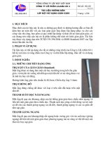
1.5
ELETRONIC CABINET KEY
A: Machine ON: Light A will on
when machine power on (as picture
1), and key (B) in right side. Please
don’t open electronic cabinet when
machine power on, to avoid the risk
of electric shock
(Picture 1)
B: Service Mode: Light (A) is off and
Key(B) switch to left (as picture
2) . Machine can’t power on, and
key can take away. Maintenance
personnel keep the key (as
picture 3) to avoid other person
to power on machine during
maintenance.
(Picture 2)
(Picture 3)
HELLER MÁQUINAS - HERRAMIENTA, S. L
C/Nicolas de Bussi, 44 03203-ELCHE (Alicante), España
TEL: +34 965 430 014 FAX: +34 965 431 195
E-mail:
1.6
BUILT-IN SPINDLE WARM UP
AL1030 PLEASE EXECUTE M77 TO WARM UP SPINDLE will show up every time power on.
Please execute M77 at MDI mode to complete spindle warm up. The alarm will off after warm up.
Please use balance tool holder and tooling and avoid any crash to ensure spindle life.
1.6.1 Notice of built-in spindle
1. Please manual rotary spindle to see if smooth before run spindle.
2. Check cooler if function well before use spindle
3. Check if noise or temperature up during warm up. If yes, please stop machine and check.
4. Execute M77 (9005) first before use spindle
5. DON’T RUN SPINDLE WITHOUT TOOL HOLDER. Spindle must clamping a balance
tool holder before rotary.
6. Tool holder must balance level as ≦G2.5. A not balance tool holder may damage spindle
7. Don’t use less 3000rpm/min for cutting.
8. Spindle need to stop 1 hour at least when run more than 23 hours.
9. Spindle uses high accuracy bearing, need to use balance tool holder. And any collision
may damage spindle.
10. Spindle nose has air blast, pressure is 1.0~1.5kgf/cm. Don’t use air gun to blast spindle
to avoid chip, coolant into spindle.
1.7 Machine restart
1. Please press emergency stop when checking machine.
2.Please check chapter 7-8 for detail
3. If need to replace parts, please check if correct first.
4. Please check parts, signal all correct after replacement.
5. If parts about safety, such as emergency stop, safety locker, safety module, please
double and rechecking if all correct very carefully. Function well at least 3 times after change
parts.
6. After exclude alarm, please follow step to restart machine:
a:Make sure machining area without people and tools
b:Release emergency stop
c:Machine back to normal condition
HELLER MÁQUINAS - HERRAMIENTA, S. L
C/Nicolas de Bussi, 44 03203-ELCHE (Alicante), España
TEL: +34 965 430 014 FAX: +34 965 431 195
E-mail:
2 SPECIFICATIONS
2.1Box Way
2.1.1 Four-box way
QV159
MODEL
TABLE
TABLE SIZE (mm)
TRAVEL RANGES (XxYxZ mm)
MAX. TABLE LOAD (Kgs)
1700x850
1500/900/850
2000
SPINDLE NOSE TO TABLE SURFACE
(mm)
150~1000
18x150x5
T-SLOT (Width x Distance x Number mm)
SPINDLE
TOOL SHANK & PULL STUD
SPINDLE INNER DIAMETER (mm)
ISO40
Ø 70
950
40-8000(10000/12000)
L 40~2000,H 2001~8000
10000(12000/15000)
950
11/15
SPINDLE CENTER TO COLUMN (mm)
SPINDLE SPEED (rpm) Belt
SPINDLE SPEED (rpm) Gear
SPINDLE SPEED (rpm) Direct drive
DRAW BAR FORCE (Kgf)
MAIN MOTOR (con/30min kW)
FEED RATE
RAPID FEED RATE (X/Y/Z m/min)
FEED RATE (X/Y/Z mm/min)
16/16/12
8000
AXIS SERVO MOTOR
MITSUBISHI
kW
FANUC
kW
SIEMENS
kW
HEIDENHAIN kW
HG453(4.5)
α22/3000i(4.0)
1FK7101 (7.03)
QSY155F(6.03)
AUTO TOOL CHANGER
MAG TYPE
CAM TYPE
TOOL SELECTION (Bi-direction)
TOOL STORAGE CAPACITY (PCs)
MAX. TOOL DIAMETER (mm)
MAX. TOOL LENGTH, WEIGHT
PLATE/DISK
GENOVA/DAUL ARM
ABSOLUTE/RANDOM
20/24(30)
Ø 100/Ø90(Ø75)
250mm,8Kgs
MISCELLANEOUS
(Kg/cm2)
AIR REQUIREMENT
VOLTAGE
POWER REQUIREMENT (KVA)
COOLANT TANK CAPACITY (L)
MACHINE WEIGHT (KGs)
FLOOR SPACE (LxWxH mm)
PACKING SIZE (LxWxH mm)
6
200V,3Ph,50/60Hz
40
300
14000
4050x2980x3200
4450x3080x3600
HELLER MÁQUINAS - HERRAMIENTA, S. L
C/Nicolas de Bussi, 44 03203-ELCHE (Alicante), España
TEL: +34 965 430 014 FAX: +34 965 431 195
E-mail:
2.2Accessories
Description
Coolant Pump, MTH4-30/3
Coolant Pump, MTH4-60/3
Pump for Chip Clean, MTA120-180
Pump for Chip Clean, MTA200-250
Sub Pump for CTS, CM10-2
Sub Pump for CTS CM5-3
,
Main Pump for CTS, 40bar MTS20-40
Main Pump for CTS, 20bar MTR3-33/33
,
Main Pump for CTS, 20bar CR3-23
,
Main Pump for CTS, 20bar CR3-36
,
Heat Exchanger, EA-3A
Spindle Oil Cooler, CO-4PTS-20L
Spindle Oil Cooler, CO-8P2TS-30L
Lubrication Pump, TM-302FW-T4P
Lubrication Pump, TM-302FW-T2P
Oil Pressure Pump, 30L
Magazine of Armless Type ATC
Magazine of Arm Type ATC(#40)
Arm type Auto Tool Changer(#40)
Magazine of Arm Type ATC(#50)
Arm type Auto Tool Changer(#50)
Screw Type Chip Conveyor
Chain Type Chip Conveyor
2.3 How to Choose 4th
Model
4th&5th Size
CNC151R
CNC201R
CNC251R
CNC321R
CNC321RV
CNC401RV
CNC501RV
CNCT202RB
CNCT321
CNCT451
QV159
Electrical Data
3Ø, 220/380V, 60/50Hz, 530W, 2.31/1.34A
3Ø, 220/380V, 60/50Hz, 720W, 3.36/1.95A
3Ø, 220/380V, 60/50Hz, 730/440W, 2.1/1.47A
3Ø, 220/380V, 60/50Hz, 1270/790W, 3.48/2.78A
3Ø, 220/380V, 60/50Hz, 1600/1050W, 6.6/3.3A
3Ø, 220/380V, 60/50Hz, 530W, 2.31/1.34A
3Ø, 220/380V, 50Hz, 750W, 3.2/1.86A
3Ø, 220/380V, 50Hz, 3000W, 12.6/6.85A
3Ø, 220/380V,60Hz,3000W,11.8/6.8A
3Ø, 220/380V,50Hz,3000W,12/6.9A
1Ø, 220V, 50/60Hz, 300W, 0.3A
3Ø, 220/380V, 60/50Hz, 905W, 4.5/4.0A
3Ø, 220/380V, 60/50Hz, 1600W, 5.5/4.8A
1Ø, 220V, 60/50Hz, 150W, 3.0A
1Ø, 220V, 60/50Hz, 150W,3.1A
3Ø, 220V, 60/50Hz, 750W, 1.7/3A
1Ø, 110/220V, 60/50Hz, 40W, S 1:25, 1/0.5A
3Ø, 220/380V, 60/50Hz, 370W, S 1:40
3Ø, 220/380V, 60/50Hz, 750W, S 1:10
3Ø, 220/380V, 60/50Hz,370W,S 1:25
3Ø, 220/380V, 60/50Hz,865W,S 41:48
3Ø, 220/380V, 60/50Hz, 200W, S 1:90, 0.8/0.46A
3Ø, 220/380V, 60/50Hz, 200W, S 1:120, 0.8/0.46A
Model
ALL
Upper 159
ALL
Upper 159
CTS
CTS
CTS
CTS
CTS
ALL
ALL
Gear Box
ALL
LV500
4TH
HELLER MÁQUINAS - HERRAMIENTA, S. L
C/Nicolas de Bussi, 44 03203-ELCHE (Alicante), España
TEL: +34 965 430 014 FAX: +34 965 431 195
E-mail:
2.4 Shank & Pull Stud
HELLER MÁQUINAS - HERRAMIENTA, S. L
C/Nicolas de Bussi, 44 03203-ELCHE (Alicante), España
TEL: +34 965 430 014 FAX: +34 965 431 195
E-mail:
HELLER MÁQUINAS - HERRAMIENTA, S. L
C/Nicolas de Bussi, 44 03203- ELCHE (Alicante), España
TEL: +34 965 430 014 FAX: +34 965 431 195
E-mail:
HELLER MÁQUINAS - HERRAMIENTA, S. L
C/Nicolas de Bussi, 44 03203-ELCHE (Alicante), España
TEL: +34 965 430 014 FAX: +34 965 431 195
E-mail:
2.5 Table Size
Model
QV159
A
1500
B
900
C
850
D
1700
E
850
F
5 x 150
G
275
H
150
J
0
K
50
L
150
2.6 Floor Area
Model
QV159
A
B
C
4050 2900 3500
HELLER MÁQUINAS - HERRAMIENTA, S. L
C/Nicolas de Bussi, 44 03203- ELCHE (Alicante), España
TEL: +34 965 430 014 FAX: +34 965 431 195
E-mail:
2.7 Operation Area
HELLER MÁQUINAS - HERRAMIENTA, S. L
C/Nicolas de Bussi, 44 03203-ELCHE (Alicante), España
TEL: +34 965 430 014 FAX: +34 965 431 195
E-mail:
2.8 Dimensional
HELLER MÁQUINAS - HERRAMIENTA, S. L
C/Nicolas de Bussi, 44 03203- ELCHE (Alicante), España
TEL: +34 965 430 014 FAX: +34 965 431 195
E -mail:
2.9 M Code List
1.◎ →STANDARD, ※→OPTION, NA→NONE.
2. Format: Txx
M06
M CODE FUNCTION
00
Program stop
01
Optional program stop
02
Program end
03
Spindle CW
04
Spindle CCW
05
Spindle stop
06
Automatic tool change *NOTE (2)
07
Mist ON
08
Coolant on
09
Coolant off &mist OFF
10
Tool kit ON or water through spindle ON
11
Tool kit OFF or water through spindle OFF
12
Mist OFF
13
Spindle cw & coolant ON
14
Spindle ccw & coolant ON
15
Chip clean ON
16
Chip clean OFF
19
Spindle orientation
21
Magazine right (PLATE type)
22
Magazine left(PLATE type)
23
Pot up (DAUL ARM type)
24
Pot down(DAUL ARM type)
25
Tool clamp
26
Tool unclamp
27
Renishaw interface power ON
28
Renishaw interface power OFF
29
Rigid tapping
30
Program end & rewind
35
–4th axis clamp
36
–4th axis unclamp
37
Axis index cycle start
38
Water curtain on spindle
ON
39
Water curtain on spindle OFF
40
Tool KIT-2 ON
41
Tool KIT-2 OFF
43
Gear at Low position
44
Gear at Hi position
45
Chip conveyor ON
46
Chip conveyor OFF
47
Chip auger ON
48
Chip auger OFF
50
Auto door open
Fanuc
◎
◎
◎
◎
◎
◎
◎
◎
◎
◎
◎
◎
◎
◎
◎
◎
◎
◎
◎
◎
◎
◎
※
※
※
※
※
※
※
※
※
※
※
※
※
※
※
※
※
※
※
NA
Mitsubishi
◎
◎
◎
◎
◎
◎
◎
◎
◎
◎
◎
◎
◎
※
※
※
※
◎
◎
◎
◎
◎
◎
◎
NA
NA
NA
◎
◎
◎
※
※
※
※
※
※
※
※
※
※
※
※
HELLER MÁQUINAS - HERRAMIENTA, S. L
C/Nicolas de Bussi, 44 03203-ELCHE (Alicante), España
TEL: +34 965 430 014 FAX: +34 965 431 195
E-mail:
51
54
55
M CODE
56
57
58
59
60
61
62
64
65
66
67
68
69
70
71
72
74
75
76
78
79
80
81
82
83
84
85
87
88
89
90
91
92
93
94
95
98
99
128
Auto door close
Table down
Table up
(APC sub prg use)
(APC sub prg use)
FUNCTION
Table clamp
(APC sub prg use)
Table unclamp
(APC sub prg use)
Table rotate A
(APC sub prg use)
Table rotate B
(APC sub prg use)
Auto plate change
(Call Sub prg O9002)
Mirror image x OFF
Mirror image y OFF
Mirror image 4th OFF
APC confirm check
(APC sub prg use)
Start tool change
(ATC sub. Prg use)
Begin of ATC. Subroutine (ATC sub. Prg use)
End of ATC subroutine
(ATC sub. Prg use)
Search spindle tool NO.
(ATC sub. Prg use)
Search T-code tool NO.
(ATC sub. Prg use)
Mirror image x ON
Mirror image y ON
Mirror image 4th ON
APC select A-table
(call Sub prg 9003)
APC select A-table
(call Sub prg 9004)
Air through system ON
Air through system OFF
Customer function 1-ON
Customer function 1-OFF
Customer function 2-ON
Customer function 2-OFF
Customer function 3-ON
Customer function 3-OFF
Programmable nozzle
(sub prg. 9005 use)
Programmable nozzle
(sub prg. 9005 use)
Programmable nozzle
(sub prg. 9005 use)
Magazine Ref. search & Table initial
Begin of ATC. Subroutine (ATC sub. Prg use)
Begin of ATC. Subroutine (ATC sub. Prg use)
Begin of ATC. Subroutine (ATC sub. Prg use)
Begin of ATC. Subroutine (ATC sub. Prg use)
Begin of ATC. Subroutine (ATC sub. Prg use)
Call sub-program
Sub-program return
Programmable nozzle
(call O9005 )
◎
◎
◎
◎
◎
◎
◎
◎
◎
◎
◎
◎
◎
◎
NA
※
※
※
※
※
Fanuc
※
※
※
※
※
Mitsubishi
※
※
※
※
※
※
※
※
※
※
※
※
※
※
※
※
※
※
※
※
※
※
※
※
※
◎
◎
◎
◎
◎
◎
◎
◎
◎
◎
◎
◎
◎
◎
※
※
※
※
※
※
※
※
※
※
※
※
※
※
※
※
※
※
※
※
HELLER MÁQUINAS - HERRAMIENTA, S. L
C/Nicolas de Bussi, 44 03203-ELCHE (Alicante), España
TEL: +34 965 430 014 FAX: +34 965 431 195
E-mail:
2.10 G Code List
S : STANDARD
G CODE
GROUP
00
FUNCTION
O : OPTION
S/O
Positioning (rapid traverse)
S
◇
Linear interpolation (cutting feed)
S
◆
02
Circular/helical interpolation CW
S
03
Circular/helical interpolation CCW
S
04
Dwell, exact stop
S
09
Exact stop check
S
Program parameter input/compensation input
S
11
Program parameter input cancel
S
12
Circular cut OFF CW
O
13
Circular cut OFF CCW
O
17
Plane selection X-Y
S
◆
Plane selection Z-X
S
◇
Plane selection Y-Z
S
◇
Inch command
S
◇
21
Metric command
S
◆
27
Reference point return check
S
28
Reference point return
S
29
Return from reference point
S
30
2nd to 4th reference point return
S
30.1
Tool position return 1
O
30.2
Tool position return 2
O
Tool position return 3
O
30.4
Tool position return 4
O
30.5
Tool position return 5
O
30.6
Tool position return 6
O
Skip function
S
31.1
Step Skip function 1
O
31.2
Step Skip function 2
O
31.3
Step Skip function 3
O
Thread cutting
O
34
Special fixed cycle (bolt hole circle)
O
35
Special fixed cycle (line at angle)
O
36
Special fixed cycle (are)
O
Automatic tool length measurement
O
Special Fixed cycle (grid)
O
38
Tool nose R compensation vector designation
O
39
Tool nose R compensation corner arc
S
40
Tool nose R compensation cancel
S
Tool nose R compensation left
S
42
Tool nose R compensation right
S
43
Tool length + direction
S
Tool length - direction
S
Tool length cancel
S
01
10
18
01
00
02
19
20
30.3
06
00
31
33
37
01
00
37.1
41
44
49
07
08
◆
◆
HELLER MÁQUINAS - HERRAMIENTA, S. L
C/Nicolas de Bussi, 44 03203-ELCHE (Alicante), España
TEL: +34 965 430 014 FAX: +34 965 431 195
E-mail:
50.1
19
51.1
G CODE
GROUP
52
00
G command mirror image cancel
S
G command mirror image ON
S
FUNCTION
S/O
Local coordinate system setting
O
53
Machine coordinate system selection
O
54
Work coordinate system 1 selection
S
55
Work coordinate system 2 selection
S
Work coordinate system 3 selection
S
57
Work coordinate system 4 selection
S
58
Work coordinate system 5 selection
S
59
Work coordinate system 6 selection
S
Single direction positioning
S
Exact stop check mode
O
56
60
12
00
61
62
13
◆
Automatic corner override
S
63
Tapping mode
O
64
Cutting mode
O
Macro call
S
Macro modal call A
O
Macro modal call B
O
67
Macro modal call cancel
S
73
Fixed cycle (step)
S
74
Fixed cycle (reverse tap)
S
76
Fixed (fine boring)
S
80
Fixed cycle cancel
S
81
Fixed cycle (drill/spot drill)
S
82
Fixed cycle (drill/counter boring)
S
Fixed cycle (deep drilling)
S
84
Fixed cycle (tapping)
S
85
Fixed cycle (boring)
S
86
Fixed cycle (boring)
S
87
Fixed cycle (back boring)
S
88
Fixed cycle (boring)
S
89
Fixed cycle (boring)
S
Absolute value command
S
◇
Incremental command value
S
◆
65
00
66
66.1
83
90
14
09
03
91
◆
◆
◆
92
00
Machine coordinate system setting
S
94
05
Asynchronous feed (per-minute feed)
O
◆
Synchronous feed (per-revolution feed)
O
◇
Constant surface speed control ON
O
Constant surface speed control OFF
O
Fixed cycle initial level return
S
Fixed cycle R point in level return
S
95
96
17
97
98
99
10
NOTE 1. Codes marked with ◆ are codes that must be or are selected in the initial state.
The codes marked with ◇ are codes that should be or are selected in the initial state by the parameters.
NOTE 2. If two or more G codes from the same code are commanded, the latter G code will be valid.
NOTE 3. Please refer the details with program manual.
msi,
965
TEL:
ELCHE
sEspaña
C/Nicolas
HERRAMIENTA,
H
Á
QUINA
S
-E
mail:
ELLER
ail:
44
430
+34
03203
(Alicante),
014
de
M FAX:
Bu +34
S. 965
L 431 195
2.11 AC Spindle Motor List
HELLER
Q
mail:
sELCHE
C/Nicolas
ssi,
TEL:
España
965
m
E
HERRAMIENTA,
H
Á
QUINA
-S
si,
LCHE
ELLER
ail:
UINA
44
430
+34
03203
(Alicante),
014
de
M FAX:
Bu +34
S. 965
L 431 195
1kgm=9.807Nm
Con/30Min
kW
Base
RPM
Max. speed
RPM
Torque
Nm
SJ-D5.5/120-01,SPJ3-55
3.7/5.5
1500
12000
23.6
SJ-D7.5/100-01, SPJ3-75
5.5/7.5
1500
10000
35
SJ-D7.5/120-01, SPJ3-75
5.5/7.5
1500
12000
35
SJ-D11/80-01, SPJ3-110
7.5/11
1500
8000
SJ-D11/100-01, SPJ3-110
7.5/11
1500
10000
Type, Driver
Flange
AxØGxØDx ØHxE
Weight
kg
Model
174x150x185x28x60
39
300/500
204x180x215x32x80
204x180x215x32x80
53
85
53
85
47.7
204x180x215x48x110
64
Under 147-ISO40
47.7
204x180x215x48x110
64
Under 147-ISO40
126-ISO50
SJ-V15-01ZT, SP-200
11/15
1500
8000
70
250x230x265x48x110
110
SJ-V18.5-01ZT, SP-200
15/18.5
1500
8000
95.5
250x230x265x48x110
110
SJ-V22-01ZT, SP-240
18.5/22
1500
8000
118
250x230x265x55x110
135
1PH8103-2NG02
7/9.25
2000
9000
33.4
40
85
1PH8107-2NF02
9/12
1500
9000
57
196x180x215x38x80
196x180x215x38x80
73
Under 116
1PH8133-2ND02
12/16
1000
8000
114.6
260x250x300x42x110
90
Under 159
1PH8133-2NG02
20/27.5
2000
8000
95.5
260x250x300x42x110
90
3.7/5.5
1500
12000
23.5
182x150x185x28x60
46
300/500
5.5/7.5
1500
12000
35
204x180x215x32x80
51
85
7.5/11
1500
10000
47.7
204x180x215x48x110
80
Under 147-ISO40
αiIT8/12000, SPM-11i
7.5/11
1500
12000
47.7
204x180x215x48x110
80
αiI12/10000, SPM-15i
11/15
1500
10000
70
250x230x265x48x110
95
αiI12/12000, SPM-15i
11/15
1500
12000
70
250x230x265x48x110
95
15/18.5
1500
10000
95.4
250x230x265x48x110
110
18.5/22
1500
10000
117.7
250x230x265x55x110
125
22/26
1500
10000
140
250x230x265x55x110
143
Controller
MITSUBSHI
Upper 117-ISO50
Upper 159-ISO40
αiI3/12000, SPM-11i
αiIT3/12000, SPM-11i
αiI6/12000, SPM-11i
αiIT6/12000, SPM-11i
αiI8/10000, SPM-11i
αiI8/12000, SPM-11i
Upper 159-ISO50
SIEMENS
Under 147-ISO40
126-ISO50
Upper 117-ISO50
Upper 159-ISO40
-22i
αiI15/10000, SPM
αiIT15/10000, SPM-22i
αiI18/10000, SPM -22i
αiI22/10000, SPM-26i
αiIT22/10000, SPM
-26i
Upper 159-ISO40
Upper 159-ISO50
FANUC
1kgm=9.807Nm
Flange
Weight
AxØGxØDx ØHxE
174x150x185x28x60
Kg
46
300/500
85
52.5
204x180x215x48x110
204x180x215x48x110
51
80
Under 147ISO40
9000
35
204x180x215x32x80
52
85
1500
9000
47.7
204x180x215x48x110
59
Under 147-ISO40
11/15.5
1500
8000
70
250x230x265x48x110
94
Upper 159-ISO40
15/22
1500
8000
95.5
250x230x265x48x110
94
Upper 159-ISO50
FM7-A185-S1C0-E01,SPD2.85
18.5/26
1500
8000
117.8
250x230x265x48x110
120
FM7-B120-S1C0-E01,SPD2.75
12/18.5
1000
8000
114.4
250x230x265x48x110
120
QAN200L,UM112D
7.5/11.5
1500
9000/12000
47.8
198x180x215x38x80
68
85
QAN200U,UM112D
10/14
1500
9000/12000
63.7
198x180x215x38x80
83
Under 147-ISO40
QAN200UH,UM112D
10/12.5
1500
12000/15000
63.7
198x180x215x38x80
91
Under 147-ISO40
QAN260L,UM113D
20/25
1500
8000/10000
127.3
262x250x300x42x110
135
Upper 159-ISO50
QAN260W ,UM112D
12/17.5
750
8000/10000
152.8
158
QAN260U,UM114D
24/30
1500
8000/10000
152.8
262x250x300x42x110
262x250x300x42x110
Con/30Min
kW
Base
RPM
Max. speed
RPM
Torque
Nm
βiI6/10000, SVSP-11
5.5/7.5
1500
10000
26.3
βiI8/10000, SVSP-11
7.5/11
1500
10000
35.8
-15
11/15
1500
8000
5.5/7.5
1500
FM7-A075-S1C1-E01,SPD1.35
7.5/11
FM7-A110-S1C0-E01,SPD2.5
FM7-A150-S1C0-E01,SPD2.75
Type, Driver
βiI12/8000, SVSP
FM7-A055-S1C1-E01,SPD1.25
158
Model
Controller
FANUC
FAGOR
HEIDENHA IN
Upper 159-ISO50