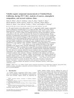
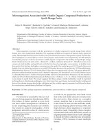
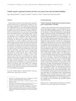
Optical Fiber Sensors to Detect Volatile Organic Compound in Sick Build- ing Syndrome Applications potx
Bạn đang xem bản rút gọn của tài liệu. Xem và tải ngay bản đầy đủ của tài liệu tại đây (388.56 KB, 8 trang )
The Open Construction and Building Technology Journal, 2010, 4, 113-120 113
1874-8368/10 2010 Bentham Open
Open Access
Optical Fiber Sensors to Detect Volatile Organic Compound in Sick Build-
ing Syndrome Applications
Cesar Elosua*
,1
, Candido Bariain
2
and Ignacio Raul Matias
3
1
Department of Electric and Electronic Engineering, Public University of Navarra, Edificio de los Tejos, Pamplona,
Spain;
2
Department of Electric and Electronic Engineering, Public University of Navarra, Edificio de los Tejos, Pam-
plona, Spain;
3
Department of Electric and Electronic Engineering, Public University of Navarra, Edificio de los Tejos,
Pamplona, Spain
Abstract: Health issues, such as Sick Building Syndrome (SBS), are being taken into account in new constructions,
houses and several non industrial environments. SBS produces several manifestations, for example, respiratory irritative
symptoms, headache and fatigue. It is caused by several factors. Most of them are related with the air quality, and the
presence of Volatile Organic Compounds (VOCs), among other parameters. It is obvious that is very important to keep
these parameters under control, and so, the development of new devices to achieve this is more and more interesting dur-
ing last few years. Some important features using sensors for this application are robustness, easy installation, on line and
real time use. Although there are electronic devices already available, optical fiber sensors offer all the performances men-
tioned before, as well as other ones exclusive of this technology: sensors networking and electromagnetic immunity
mainly. In this work, we will show a review about the SBS aim, the sensing architectures of optical fiber technology, and
the opportunities that it has in this increasing market niche.
1. INTRODUCTION
Health issues related to non industrial indoor environ-
ments are getting more importance due to their effect on hu-
mans. Poor ventilation combined with chemical pollutants
can yield to a bad Indoor Air Quality (IAQ). This may even
cause some health symptoms to people working or living
inside the building; on the other hand, certain temperature
and humidity conditions could also make easier the appear-
ance of biological agents such as molds. These factors make
easier the appearance of Sick Building Syndrome (SBS); this
was first identified in the 1970s decade [1], and the World
Health Organization defined it on 1983 [2] as non specific
complaints, including upper - respiratory irritative symp-
toms, headache, fatigue, usually associated with a particular
building by their temporal pattern of occurrence and cluster-
ing among inhabitants or colleagues. Volatile organic com-
pounds (VOCs) are the main pollutants (which will be ex-
plain in detail later), and they have many potential sources.
This way, it is very important to detect them and to know
their concentrations. This makes necessary the use of sensors
to handle with SBS: they have to alert when the IAQ is not
satisfactory and when they detect the presence of biological
agents as well.
There are electronic devices able to detect air pollutants,
but in this context, optical fiber technologies offer some in-
teresting features: real time and on line operation, light
weight, electro magnetic immunity (office buildings are full
of this type of noise), and the possibility of multiplexation
(handle with several optical signals in just one optical cable),
*Address correspondence to this author at the Department of Electric and
Electronic Engineering, Public University of Navarra, Edificio de los Tejos,
Pamplona, Spain; Tel: +34 948 169328; Fax: +34 948 169720;
E-mail:
just to mention a few. Regarding to biological agents detec-
tion, optical fiber is an inert substrate and needs no electrical
signals to operate, so different enzymes can be fixed on it
[3]. Thanks to these features, SBS applications are a poten-
tial market niche for optical fiber sensors.
In this article, we will start describing with more detail
SBS, just to avoid confusions with other syndromes related
with certain pathogen micro organism, specifying its main
sources as well. After that, a brief description about optical
technology will be shown. In the fourth section, we will in-
troduce some concepts and classifications of optical fiber
sensors that will help to follow the article; after this, differ-
ent kind of sensors and topologies will be described, detail-
ing in each case the potential use in SBS applications. Fi-
nally, we will remark the challenges that optical fiber sensors
have in this context, with the newest advancements and the
problems that have to overcome to have a successful implan-
tation in this field.
2. SICK BUILDING SYNDROME: A BRIEF DE-
SCRIPTION
SBS has to be distinguished from other well-known
building-related illnesses caused by specific exposures in
indoor environments [4] ; some of these illnesses are rhinitis,
asthma and pneumonitis (due to exposure to moulds, spores,
or allergenic chemicals). Building outbreaks of infectious
diseases (legionnaires, viral infections or tuberculosis) are
well recognized [5]. A single exposure can result in more
than one type of these responses. Typically in these disor-
ders, evidence of clustering of cases in a small group (or host
idiosyncrasy) provides clues to a specific building-related
illness and a single causal factor. This is not the case of SBS:
it can rarely be attributed to a single specific exposure.
First evidences about SBS were detected in 1970s, as a
result of reducing fresh air supply and poor performance of
114 The Open Construction and Building Technology Journal, 2010, Volume 4 Elosua et al.
the HVAC system. There are other factors that contribute to
the SBS: synthetic materials widely in building construction,
a higher number of workers in office, the use of personal
computers drying the air and cleaning or perfuming prod-
ucts, just to mention a few. This way, the cause of SBS can
not be established with a single or even a group of environ-
mental factors [6]. One of the most popular theories for some
years was that the main SBS source was the effect of several
VOCs present at low concentrations that, all together, pro-
duce a toxic effect. Recently, other factors related with bio-
logical contaminants and psychosocial matters are consid-
ered as direct sources of SBS [7]. In Table 1, a brief list of
the main factors that are related with SBS is shown. Any-
way, many factors affect this syndrome, and the presence of
VOCs is taken into account in all theories, so its detection
and control are very important to handle with the SBS.
Table 1. Main Environmental Factors Related to SBS
Most Important Factors Related with SBS
VOCs Formaldehyde
Solvents
Paints and resins
Dust Dirt
Construction
Paper dust
Biological Agents Bacteria
Fungis
Pollen
Viruses
OutDoor Agents Vehicle exhaust
Industrial exhaust
Human Activity Carbon dioxide
Perfume
Physical Factors Temperature
Humidity
3. OPTICAL FIBER SENSORS TECHNOLOGY
Our purpose is not to provide a detail explanation about
this field, just a few concepts that will help us to link it with
the SBS application needs. It is well known that optical fiber
and photonic technologies introduced a great advance in
communication systems: the main reasons were, among oth-
ers, low attenuation of optical signals and a higher capability
to transfer information compared with electronic communi-
cations along greater distances. The reader can find a de-
tailed explanation about this in [8]. With the optimal results
obtained in this field, it was thought that this technology
could be also incorporated to other areas, for example, sens-
ing devices and systems. Compared to other solutions avail-
able, optical fiber is a passive substrate that does not need
any electrical signal to operate, just light: this is a great fea-
ture in environments where there is an explosion risk be-
cause of the presence of some gases [9]; they can be used in
places with high levels of electromagnetic noise, as the fiber
is a dielectric material [10]; another good feature is the pos-
sibility of integrate several sensors in one network, even
each one can detect different parameters (multiplexation
capability). Of course, there are some drawbacks: photonic
devices are still more expensive than electronic ones, and
this second technology is much more mature. Nowadays,
there are electronic sensors for almost all applications, and
they are cheaper and easy to obtain than optical fiber ones;
but there are some market niches were these sensors are
widely used thanks the properties mentioned above. So, this
technology has to find the specific applications where it of-
fers features that electronic devices does not, as is pointed in
several optical fiber sensors reviews [11-13]. One of this
fields, is the detection of VOCs and gases [14], and so, the
prevention of SBS.
4. SENSOR CONFIGURATION & VOCs DETECTION
These devices work with optical signals, this is light, and
as sensors, there must be an interaction (transduction) be-
tween the light that travels through the fiber and the parame-
ter to detect, in our case, different VOCs and gases. There
are some criteria to classify this kind of sensors, for example,
the change that light signal suffers: it can be measured in
terms of power, frequency or phase (modulation). Another
option is related with the place where the transduction oc-
curs, this is, inside or outside the fiber, dividing the sensors
in two groups: intrinsic and extrinsic [15].
4.1. Extrinsic Sensors
In this case, the fiber just guides the light to an area
where the measurement takes place, and couples this signal
once it has been modulated by the VOC or gas (fig. 1). It is
important to note that this solution has been used in real ap-
plications [16]: the sensing system only needs to install the
fiber, and it is not necessary any treatment to make it sensi-
tive to the gas to detect. This sensing architecture is related
to spectrography: the wavelength (frequency) of light that
travels through the fiber matches one spectral absorption line
of the gas to detect. In Table 2 there are shown the absorp-
tion lines gases of interest (CO, CO
2
, O
2
, NH
3
, CH
4
).
With this scheme, very selective sensors can be obtained,
and with just one light source and one receptor, a multipoint
sensor network can be implemented, for example, in a build-
ing. Typically, the optical fibers are placed one opposite the
other, so they have to be accurately aligned; looking for this,
micro cells are used to connect the fibers and avoid noise
due to a bad alignment. Other gases can interfere the meas-
ure, but it can be overcome making the input signal more
robust using modulations [17].
Depending on the final application, it might be interest-
ing the use of a multi point sensor network able to detect
several gases (Fig. 2), no just one, as mention above. It can
be done with the same configuration, and only the optical
source has to be changed to achieve this. The idea is that,
along time, the optical source tunes the wavelength of the
light emitted, matching it with the absorption line of differ-
ent gases. This is known as Wave Spectral Modulation
(WSM) [18].
Optical Fiber Sensors to Detect Volatile Organic Compound The Open Construction and Building Technology Journal, 2010, Volume 4 115
Another possibility for extrinsic sensors is that change of
the light can be accomplished by a chemical agent. This way,
a substrate, with a dye sensitive to the target gas, is placed in
the optical path of the light. The optical properties of this
obstacle are modified in presence of the gas or vapor, and so,
the light that passes through it [19] (or that is reflected [20]),
suffers a detectable change. Using different dyes, different
gases can be detected, and so, this solution allows to design a
network with sensors able to handle with several targets.
Table 2. Gases Related with SBS with their Spectral Absorp-
tion Lines and Strengths
Gas
Absorption Line
(nm)
Line Strength
(cm
-2
atm
-1
10
-2
)
NH
3
1544 0.925
CO 1567 0.0575
CO
2
1573 0.04
CH
4
1667 1.5
H
2
O 1365 52.5
O
2
761 0.019
NO
2
800 0.125
4.2. Intrinsic Sensors
As it was said before, in this type of sensors the optical
fiber plays a more active role, as the transduction between
the target and the light takes place in or on it. In most cases,
a chemical layer is fixed onto the fiber, affecting the way
light travels through it, although there are some examples
where the fiber itself acts as the sensitive material, as will be
shown later. Finally, the chemical dye can emit an optical
signal depending on the surrounding environment, and
hence, use this to detect VOCs or gases.
4.2.1. Evanescent Wave Sensors
This was the sensor configuration most studied along the
1990s [21]. In most of them, a segment of the fiber acts as
sensing area (avoiding open paths, as in extrinsic sensors).
Optical fibers have a cladding around a core, and its proper-
ties affect the light transmitted along the fiber. The passive
cladding of the optical fiber can be replaced along a small
section, by a sensitive material, so these sensors are also
known as transmissive; this way, any change in the optical
characteristics of the dye will alter the transmission of the
light [22]. The sensitivity depends on several parameters,
mainly both the chemical properties of the dye and the light
propagation; this last one can be studied by Beer-Lambert
law [23] and ray theory approximation [24, 25] (Fig. 3).
Fig. (1). Typical configurations for extrinsic sensors: fibers embedded in a microcell where air flows (left) and light guided and coupled from
a sensing substrate.
Fig. (2). An extrinsic sensors network: each device has a path with a different length, so the signals reaches the receptor at different times,
and so, can be measured individually.
Light
Gas
Gas
Light
Gas
Gas
L
Microcell
L
L+L
Microcell
L+2L
Microcel
l
Tunable
Light
Source
Optical
Rece
p
tor
Microcell
L+3L
Source
p
116 The Open Construction and Building Technology Journal, 2010, Volume 4 Elosua et al.
One of the main problems of these sensors (and all the
sensors that need a chemical dye), is fixing the sensing mate-
rial onto the fiber. In many cases, it is in solid state and has
to be solved and then deposited. The implementation of the
sensor involves several steps: removing the cladding, solving
the material and fixing it; obviously, this process has to be
repetitive and seems to be worst than the one with extrinsic
sensors. On the other hand, chemical dyes offer an almost
unlimited number possibilities of detection of different
VOCs or gases, and among other features, this justify the
whole implementation process.
There are some chemical processes used to fix the sens-
ing material; one of the most popular is dipping the fiber into
a sol gel [26]. This is a mixture made of silica, the same ma-
terial as optical fiber. The sensing material is added to the
sol-gel solution while it is still in liquid phase, dipping the
fiber into the mixture. After drying the deposition, an opti-
cally uniform porous matrix doped with the analyte is ob-
tained. Recently, efforts have been focused on controlling
the size of the porous once the sol-gel is deposited: this can
give an additional sensing mechanism based on discrimina-
tion between organic vapor molecules depending on their
molecular size. Sol-gel solutions deposited with dip coating
technique are a typical combination used in recent years to
implement evanescent wave sensors [27]. Other important
deposition techniques are Langmuir-Blodgett [28] and the
Electrostatic Self-Assembly method (ESAm). Many research
is being pointed to this last technique as it allows to fix nano
metric layers onto substrates independently of its surface
shape, which is a great feature when implementing optical
fiber sensors [29].
Talking about the sensing materials, there are several
families sensitive to different organic solvents, having a re-
versible reaction in presence of different VOCs, which is
transduced into a change of the optical light propagated in
the fiber. Some examples are the Vapochromic complexes
[30] (which suffer a color change), polyaniline, hydrophilic
films [31] (ideal to monitorize humidity levels), and certain
polymers. New sensors based on these materials are de-
scribed in recent studies [32, 33], and offer interesting poten-
tial uses. The only limitation of these materials is that they
need to react with the target, so it is very difficult to synthe-
size one able to detect inert gases such as CO
2
or CO, very
important in IAQ.
This kind of sensors has sometimes a low sensitivity due
to the limited effect of the modified cladding on the transmit-
ted light. Some approaches have been studied so far to over-
come this problem. The fiber can be bent enhancing the in-
teraction between the light and the cladding [34]. Dimen-
sions of standard fiber are 125 μm, and after the bending
process, it might become weak, so in these cases, the em-
ployed fibers have core diameters up to 1 mm to avoid
crushing. It is also possible to coil a few meters of an optical
fiber with modified cladding [35]. Another extended solution
is based on tapering the fiber [32], increasing a lot the inter-
action between the light and the chemical dye; in this case,
as the fiber is stretched, it is weaker, so this should be only
used in applications where the sensor is not exposed to high
mechanical efforts. Finally, the sensitivity can be also in-
creased taking advantage of the fact that the light travels
through the core of the optical fiber: it consists on synthesiz-
ing a segment of optical fiber from a sol gel solution, so it
can be doped with the desired sensing material [36]; after it
is dried, it can be fused to standard fibers. This is known as
active fiber core sensors. The main drawback of this solution
is the aging effect, which is more critical than in evanescent
wave sensors.
4.2.2. Reflection Sensors
Inside the intrinsic configurations category, reflection
sensors consist of an end-cut optical pigtail, onto which a
chemical dye is deposited. As can be seen in Fig. (4), the
light is coupled from the source and is guided until the sen-
sor head, where the light interacts with the sensing deposi-
tion. Depending on the optical properties of this layer, a part
of the light will go through this interface, and another part
Fig. (3). Experimental set up for an evanescent wave sensor, with three different possibilities: removing the cladding (top-left), tapering the
fiber (top-right) and bending the fiber (down-center).
Input light
Transduced light
Input
light
Transduced
light
Optical Fiber Sensors to Detect Volatile Organic Compound The Open Construction and Building Technology Journal, 2010, Volume 4 117
will be reflected back. This process is governed by the
Fresnel’s law, and is described in detail in [37]. An optical
coupler is needed to guide the reflected signal, and is the
main device of this configuration.
The sensor head employed in this configuration is used in
the same way as chemical electrodes, and so, this type of
sensors are also called optrodes. This makes the sensor small
and easy to place, and as no cladding has to be removed,
they are more robust than transmissive sensors. The trans-
duction takes place only in the core section of the fiber,
which is a significantly smaller area than in evanescent wave
sensors; besides, reflected optical power is, in the best case,
around 4% of the incident signal on the interface. In spite
these drawbacks, its small size and high robustness justify
the use of these sensors.
Regarding to the selectivity, it is similar than with trans-
missive sensors: it depends mainly on the chemical dye fixed
onto the fiber (Fig. 5). The techniques used to fix the sensing
material are similar than the ones used in evanescent wave
sensors; among all of them, ESAm is offering the best results
in terms of reproducibility, thanks to the fact that it is an
iterative process [38]. In order to obtain the maximum re-
flected power, the end of the pig tail has to be as perpendicu-
lar as possible. The sensitivity depends a lot on the chemical
dye as well.
There are other sensing mechanisms typical of this con-
figuration, apart of the measuring just the reflected optical
power. Recently, new plastic cladding fibers (PCFs) with
wider dimensions (from 220 to 1000μm) are used to increase
the sensitivity [39]. Using them, the chemical dye can be
illuminated with a white light signal, and so, its color is re-
Fig. (4). Experimental reflective set – up. Two possible sensor heads are shown: a perpendicular ending (which maximizes the reflected opti-
cal power), and a tapered one (used when the fluorescence of the chemical dye has to be coupled into the fiber).
Fig. (5). Linear approximations between reflected optical power and relative concentration, from a sensor exposed to two dif-
ferent VOCs.
Data Register
Transduced signal
Transduced
signal
Transduced
signal
Input signal
Input signal
Optical Coupler
5
EtOH Acetone
y = 0 0454x + 0 0967
4
4,5
w
er
(dB)
y
=
0
,
0454x
+
0
,
0967
R
2
= 0,99
3
3,5
t
ed Po
w
2
2,5
e
Reflec
t
y = 0,027x + 9E-05
2
0
1
1,5
R
elativ
e
R
2
= 0,9963
0
0
,5
0
20
40
60
80
100
R
0
20
40
60
80
100
Relative Concentration(%)
118 The Open Construction and Building Technology Journal, 2010, Volume 4 Elosua et al.
flected to the detector (Fig. 6): as mentioned before, there are
some vapochromic complexes that suffer color changes in
presence of so VOCs, so this transduction can be used to
detect them. Another important mechanism is based on the
spontaneous light emission of the chemical dye when it is
excited with light at a certain wavelength. In other words, the
sensing material shows a fluorescence emission, and it is
altered by the target gas in terms of amplitude or color. One
of the most studied materials is ruthenium, and it has been
successfully used to determinate the O
2
concentration [40],
which is a very important parameter is AIQ, and so, in SBS
applications. Looking for to maximize the fluorescence cou-
pled to the fiber, some special terminations are built onto the
cut-end pigtails, usually tapers [41].
4.3. Hybrid Sensors
This configuration comes from the combination of the
ones described before. There are many possibilities to use
together sensing mechanism of reflective and evanescent
wave sensors. For example, by modifying the cladding of an
optical mirror-ended pigtail, it is guaranteed that the optical
power is modulated twice: first, when the light passes
through the sensing area to the end, and then, when the sig-
nal travels back from the mirror to the detector, passing
again through the modified cladding area [42]. It is also pos-
sible to use a bent evanescent wave mirror-ended sensor.
Another choice consists on using an active core fiber with a
reflection scheme; the effect on the transmitted light is added
to effect on the interface between the fiber and the air.
5. CHALLENGES AND OPPORTUNITIES OF OPTI-
CAL FIBER SENSORS IN SBS APPLICATIONS
So far, a brief description of different sensing approxima-
tions has been exposed. With this global point of view, now
we can see the advantages and potential applications that this
kind of sensors offers in SBS field. The main drawback is
that electronic sensors are more mature and that technology
is cheaper compared to the optical fiber one, although the
prices of optical devices are getting cheaper along last dec-
ades. Anyway, one of the most important advantages that
optical fiber sensors offer is the possibility of multiplexation.
In Fig. (7), the absorbance spectra of a sensor is shown: there
is a wide spectral range where the sensor can operate, and so,
be multiplexed with other sensors. There are proposed sev-
eral networks to handle with sensors [43], and this is very
interesting when thinking about installing them in a building.
All of them could be controlled on line and real time in par-
allel, so if one doesn’t work properly, it wouldn’t affect the
rest of the network. Besides, this network are transparent to
the sensors, this means that devices sensitive to different
VOCs can be included in the same network. This is a clear
advantage compared to other solutions such as hand held
devices [44]. Beyond the possibility of implementing a multi
sensor network, new techniques allows to determine the
temperature along a fiber network with a spatial accuracy
around 35cm [45], which, although does not have nothing to
do with VOCs or gas detection, is very attractive to SBS
applications. This sensing capability can be used superposed
to the network, so it would not interfere with the sensors
responses. This is a very interesting potential application.
In case of gas detection, WSM techniques described in
extrinsic sensors section are the best to detect low reactivity
gases, as they show a high selectivity and the use of certain
modulations minimizes the effect of other interfering gases.
This is a good way to register the concentration of CO
2
and
CO, and so, control the ventilation and IAQ. Humidity and
O
2
might be also detected by WSM, but better results are
obtained with intrinsic sensors combined with chemical
dyes. This is the same case with VOCs. Sensing materials
offer the possibility to detect a VOC if it interacts with the
sensing layer, and it most of cases, the change is reversible.
At this point, these materials show a lower selectivity com-
Fig. (6). Time response for a sensor when exposed to 3 different VOCs; the can be differentiated in terms of variation in reflected optical
power or recovery time.
0,2
EtOH Acetone Acetic Acid Diclorometane
0,1
0,15
Units
)
0,05
A
bsolute
-0,05
0
a
nce (
A
015
-0,1
A
bsorb
a
-0,2
-
0
,
15
450
700
950
1200
1450
1700
A
450
700
950
1200
1450
1700
Wavelength (nm)
Optical Fiber Sensors to Detect Volatile Organic Compound The Open Construction and Building Technology Journal, 2010, Volume 4 119
pared with WSM, as they usually react with a family for
VOCs, for example, alcohols, formaldehydes or ammonia
complexes. So, it is difficult that a sensor could react to a
certain alcohol, for example ethanol, and not to another one,
such as methanol (Fig. 7). However, it could show a signifi-
cant response to alcohols and a neglible one to other VOCs.
This way, another sensor could react to, for example, form-
aldehydes, and register a little response to alcohols. As SBS
is not affected by a single VOC, several sensors with differ-
ent selectivities can be combined to obtain fingertips to iden-
tify global VOCs mixtures that could yield to SBS. Anyway,
there are some cases where toxic vapors can be detected with
a low interference from other vapors, which the case of NO
2
[46], CHCl
3
[37] and NH
3
[47].
6. CONCLUSIONS
SBS is a health issue that has to be taken into account
both in work and house buildings. It is due not only to a sin-
gle factor, but to a global effect of physical conditions, air
quality, chemical pollutants and biological agents. Optical
fiber sensors is an emerging technology that offer attractive
issues to detect one of the factors involved in SBS, which is
the quality of air, mainly, the presence of VOCs and differ-
ent gases levels (O
2
,CO
2
,CO,NO
2
). An overview about the
main sensing configurations has been shown, pointing the
main drawbacks and advantages for each case. Just to remind
them briefly, these sensors show electromagnetic immunity
(useful in environments where electric and or electronic de-
vices are used), are light weighted, their size is small and
sensors network can be implemented thanks to their multi-
plexation capability. On the other hand, this technology is
not so developed as the electronic one, making electronic
devices cheaper. Though electronic sensors have been used
since years ago, and so, the technology is more mature and
more accessible, optical fiber sensors offer some interesting
capabilities that make them a potential alternative in the next
years in certain markets niche as SBS applications.
7. ACKNOWLEDGEMENTS
Financial support from the Spanish Comisión
Interministerial de Ciencia y Tecnología within projects
TEC2007-67987-C02-02 and TEC2007-68065-C03-01, and
FEDER funds is acknowledged.
REFERENCES
[1] D. Menzies, and J. Bourbeau, “Building-related illnesses”, The
New England Journal of Medicine, vol. 337, pp. 1524-1531, 1997.
[2] A. Thron, “The sick building syndrome: a diagnostic dilemma”,
Social Science Medicine, vol. 47(9), pp. 1307-1312, 1998.
[3] J. M. Corres, A. Sanz, F. J. Arregui, I. R. Matías, and J. Roca,
“Fiber optic glucose sensor based on bionanofilms”, Sensors and
Actuators B, vol. 131, pp. 633-639, 2008.
[4] "Occupational Safety, and Health Administration. Indoor air qual-
ity, 29 CFR”, Fed Register, 1994, pp. 15968-6039.
[5] T. Husman, “Health effects of indoor-air microorganisms”, Scandi-
navian Journal of Work, Enrionmental & Health, vol. 22, pp. 5-13,
1996.
[6] M. J. Mendell, “Non-specific symptoms in office workers: a review
and summary of the literature”, Indoor Air, vol. 3(4), pp. 227-236,
1993.
[7] H. L. M. Hodgson, and P. Wolkoff, “Volatile organic compounds
and indoor air”, Journal of Allergy & Clinical Immunology, vol. 94,
pp. 296-304, 1994.
[8] G. P. Agrawal, Fiber-Optic Communication Systems: John Wiley
& Sons, Inc., New York, 2002.
[9] H. Thomas, and J. Dubaniewicz, “Methane–air mixtures ignited by
CW laser-heated targets on optical fiber tips: Comparison of tar-
gets, optical fibers, and ignition delays”, Journal of Loss Preven-
tion in the Process Industries, vol. 19, pp. 425-432, 2006.
[10] K. Bohnert, P. Gabus, J. Kostovic, and H. Brändle, “Optical fiber
sensors for the electric power industry”, Optics and Lasers in En-
gineering, vol. 43, pp. 511-526, 2005.
[11] B. Lee, “Review of the present status of optical fiber sensors”,
Optical Fiber Technology, vol. 9, pp. 57-79, 2003.
[12] C. K. Y. Leung, “Fiber optic sensors in concrete: the future?”,
NDT&E International, vol. 34, pp. 85-94, 2001.
[13] K. Hotate, “Fiber sensor technology today”, The Japan Society of
Applied Physics, vol. 45 (8B), pp. 6616-6625, 2006.
[14] C. Elosua, I. R. Matias, C. Bariain, and F. J. Arregui, “Volatile
organic compound optical fiber sensors: a review”, Sensors, vol. 6,
pp. 1440-1465, 2006.
Fig. (7). Absorbance spectra obtained from a single sensor.
5
EtOH
A
cetone
A
cetic Acid
3
4
r
(dB)
2
3
d
Powe
0
1
0
10
1
20
R
eflecte
d
-2
-1
0
5
10
1
5
20
lative
R
4
-3
Re
-
4
Time (minutes)
120 The Open Construction and Building Technology Journal, 2010, Volume 4 Elosua et al.
[15] I. R. Matias, F. J. Arregui, and R. O. Claus, Fiber Optics Hand
Book: Fiber, Devices and Systems for Optical Communications.
Ch. 15. 1
st
ed. McGraw Hill Professional, New York, 2001, vol. 1.
[16] B. Culshaw, G. Stewart, F. Dong, C. Tandy, and D. Moodie, “Fibre
optic techniques for remote spectroscopic methane detection—from
concept to system realisation”, Sensors and Actuators B, vol. 51,
pp. 25-37, 1998.
[17] C. T. G. Stewart, D. Moodie, M. A. Morante, and F. Dong, “Design
of a fibre optic multi-point sensor for gas detection”, Sensors and
Actuators B, vol. 51, pp. 227-232, 1998.
[18] G. Whitenett, G. Stewart, K. Atherton, B. Culshaw, and W.
Johnstone, “Optical fibre instrumentation for environmental moni-
toring applications”, Journal of optics A: Pure and Applied Optics,
vol. 5, pp. 140-145, 2003.
[19] S. Christie, E. Scorsone, K. Persaud, and F. Kvasnik, “Remote
detection of gaseous ammonia using the near infrared transmission
properties of polyaniline”, Sensors and Actuators B, vol. 90, pp.
163-169, 2003.
[20] B. Kondratowicz, R. Narayanaswamy, and K. C. Persaud, “An
investigation into the use of electrochromic polymers in optical fi-
bre gas sensors”, Sensors and Actuators B, vol. 74, pp. 138-144,
2001.
[21] S. K. Khijwania, and B. D. Gupta, “Fiber optic evanescent field
absorption sensor with high sensitivity and linear dynamic range”,
Optics Communications, vol. 152, pp. 259-262, 1998.
[22] S. Khalil, L. Bansal, and M. El-Sherif, “Intrinsic fiber optic chemi-
cal sensor for the detection of dimethyl methylphosphonate”, Opti-
cal Engeeniring, vol. 43(11), pp. 2683-2688, 2004.
[23] T. A. Dickinson, K. L. Michael, J. S. Kauer, and D. R. Walt, “Con-
vergent, self-encoded bead sensor arrays in the design of an artifi-
cial nose”, Analytical Chemistry, vol. 71, pp. 2192-2198, 1999.
[24] J. Yuan, and M. A. El-Sherif, “Fiber-optic chemical sensor using
polyaniline as modified cladding material”, IEEE Sensors Journal,
vol. 3(1), pp. 5-12, 2003.
[25] A. Messica, A. Greenstein, and A. Katzir, “Theory of fiber-optic,
evanescent-wave spectroscopy and sensors”, Applied Optics, vol.
35(13), pp. 2274-2284, 1996.
[26] S. Sekimoto, H. Nakagawa, S. Okazaki, K. Fukuda, S. Asakura,
T. Shigemori, and S. Takahashi, “A fiber-optic evanescent-wave
hydrogen gas sensor using palladium-supported tungsten oxide”,
Sensors and Actuators B, vol. 2000, pp. 142-145, 2000.
[27] M. Bezunartea, J. Estella, J. C. Echeverría, C. Elosúa, C. Bariáin,
M. Laguna, A. Luquin, and J. J. Garrido, “Optical fibre sensing
element based on xerogel-supported [Au2Ag2(C6F5)4(C14H10)]n
for the detection of methanol and ethanol in the vapour phase”,
Sensors and Actuators B, vol. 134, pp. 966-973, 2008.
[28] W. Hu, Y. Liu, Y. Xu, S. Liu, S. Zhou, D. Zhu, B. Xu, C. Bai, and
C. Wang, “The gas sensitivity of Langmuir–Blodgett films of a
new asymmetrically substituted phthalocyanine”, Sensors and Ac-
tuators B, vol. 56, pp. 228-233, 1999.
[29] F. J. Arregui, I. R. Matías, and R. O. Claus, “Optical fiber gas
sensors based on hydrophobic alumina thin films formed by the
electrostatic self-assembly monolayer process”, IEEE Sensors
Journal, vol. 3(1), pp. 56-61, 2003.
[30] A. Luquin, C. Bariain, E. Vergara, E. Cerrada, J. Garrido, I. R.
Matias, and M. Laguna, “New preparation of gold–silver com-
plexes and optical fibre environmental sensors based on vapochro-
mic [Au2Ag2(C6F5)4(phen)2]n”, Applied Organometallic Chemis-
try, vol. 19, pp. 1232-1238, 2005.
[31] C. Bariain, I. R. Matıas, F. J. Arregui, and
M. López-Amo, “Opti-
cal fiber humidity sensor based on a tapered fiber coated with aga-
rose gel”, Sensors and Actuators B, vol. 69, pp. 127-131, 2000.
[32] C. Bariain, I. R. Matıas, I. Romeo, J. Garrido, and M. Laguna,
“Detection of volatile organic compound vapors by using a vapo-
chromic material on a tapered optical fiber”, Applied Physics Let-
ters, vol. 77(15), pp. 2274-2276, 2000.
[33] C. Elosua, C. Bariain, I. R. Matias, F. J. Arregui, E. Vergara, and
M. Laguna, “Optical fiber sensing devices based on organic vapor
indicators towards sensor array implementation”, Sensors and Ac-
tuators B, vol. 137, pp. 139-146, 2009.
[34] S. A. Grant, J. H. Jr. Stacher and K. Bettencourt, “Development of
sol–gel-based fiber optic nitrogen dioxide gas sensors”, Sensors
and Actuators B, vol. 69, pp. 132-137, 2000.
[35] E. Scorsone, S. Christie, K. C. Persaud, and F. Kvasnik, “Evanes-
cent sensing of alkaline and acidic vapours using a plastic clad sil-
ica fibre doped with poly(o-methoxyaniline)”, Sensors and Actua-
tors B, vol. 97, pp. 174-181, 2004.
[36] R. Falate, R. C. Kamikawachi, M. Muller, H. J. Kalinowski, and J.
L. Fabris, “Fiber optic sensors for hydrocarbon detection”, Sensors
and Actuators B, vol. 105, pp. 430-436, 2005.
[37] M. Giordano, M. Russo, A. Cusano, and G. Mensitieri, “An high
sensitivity optical sensor for chloroform vapours detection based on
nanometric film of -form syndiotactic polystyrene”, Sensors and
Actuators B, vol. 107, pp. 140-147, 2005.
[38] C. Elosua, C. Bariain, I. R. Matıas, F. J. Arregui, A. Luquin, and
M. Laguna, “Volatile alcoholic compounds fibre optic nanosensor”,
Sensors and Actuators B, vol. 115, pp. 444-449, 2006.
[39] S. Casado-Terrones, C. Elosua, C. Bariain, and A. S. Carretero,
“Volatile-organic-compound optic fiber sensor using a gold-silver
vapochromic complex”, Optical Engeeniring, vol. 45(4), pp.
044401-0444017, 2006.
[40] B. K. Otto, S. Wolfbeis, K. Goswami, and S. M. Klainer, “Fiber-
optic fluorescence carbon dioxide sensor for environmental moni-
toring”, Mikrochimica Acta, vol. 129, pp. 181-188, 1998.
[41] P. C. P. A. S. Jorge, C. C. Rosa, A. G. Oliva, and J. L. Santos,
“Optical fiber probes for fluorescence based oxygen sensing”, Sen-
sors and Actuators B, vol. 103, pp. 290-299, 2004.
[42] P. S. Grant, and M. J. McShane, “Development of multilayer fluo-
rescent thin film chemical sensors using electrostatic self-
assembly”, IEEE Sensors Journal, vol. 3(2), pp. 139-146, 2003.
[43] R. A. Pérez-Herrera, M. A. Quintela, M. Fernández-Vallejo, A.
Quintela, M. Lopez-Amo, and J. M. Lopez-Higuera, “Stability
comparison of two ring resonator structures for multiwavelength
fiber lasers using highly doped Er-fibers”, Journal of Lightwave
Technology, 2009, In press.
[44] K. Kawamura, K. Kerman, M. Fujihara N. Nagatania, T. Hashiba,
and E. Tamiya, “Development of a novel hand-held formaldehyde
gas sensor for the rapid detection of sick building syndrome”, Sen-
sors and Actuators B, vol. 105, pp. 495-501, 2005.
[45] S. Diaz, S. F. Mafang, M. Lopez-Amo, and L. Thevenaz, “A high-
performance optical time-domain brillouin distributed fiber sen-
sor”, IEEE Photonic Technology Letters, vol. 8(7), pp. 1268-1272,
2008.
[46] S. J. Mechery, and J. P. Singh, “Fiber optic based gas sensor with
nanoporous structure for the selective detection of NO2 in air sam-
ples”, Analytica Chimica Acta, vol. 557, pp. 123-129, 2006.
[47] D. Galbarra, F. J. Arregui, I. R. Matias, and R. O. Claus, “Ammo-
nia optical fiber sensor based on self-assembled zirconia thin
films”, Smart Materials and Structures, vol. 15, pp. 739-744, 2005.
Received: March 31, 2009 Revised: August 29, 2009 Accepted: August 29, 2009
© Elosua et al.; Licensee Bentham Open.
This is an open access article licensed under the terms of the Creative Commons Attribution Non-Commercial License ( />licenses/by-nc/3.0/) which permits unrestricted, non-commercial use, distribution and reproduction in any medium, provided the work is properly cited.