The space vector PWM for voltage source inverters using artificial neural networks based on FPGA
Bạn đang xem bản rút gọn của tài liệu. Xem và tải ngay bản đầy đủ của tài liệu tại đây (2.38 MB, 6 trang )
IFOST
2010 Proceedings
The Space Vector PM for Voltage Source Inverters Using
Artiicial Neural Networks Based on FPGA
Hong Hee Lee
Phan Quoc Dzung
Le Minh Phuong
School of Electrical Engineering,
HCMC University of Technology
HCMC University of Technology
University ofUlsan, Ulsan, Korea
Ho Chi Minh City, Vietnam
Ho Chi Minh City, Vietnam
Le Dinh Khoa
Nguyen Truong Dan Vu
HCMC University of Technology
HCMC University of Technology
Ho Chi Minh City, Vietnam
Ho Chi Minh City, Vietnam
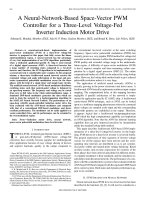
Abstract- This paper presents space vector PWM algorithm for
six- switch three-phase inverters (SSTPI) using Artiicial Neural
Networks (ANN) based on the ready-to-use ield-programmable
VSI
+ ---1--------,
gate array (FPGA) technology. ANN is used to calculate ON-OFF
time for six switches when given the angle and modulation index
of
required
voltage
space
vector.
This
approach
has
the
advantage of very fast implementation of an Space Vector PWM
Ud
c
(SVPWM) algorithm that can increase the converter switching
Power
system or
Drive
frequency, particularly when the ield-programmable-gate-array
(FPGA) technology is used in the modulator. This SVPWM is
also validated experimentally using FPGA-XUP VIRTEX II PRO
from Xilinx in SSTPI-IM system for under modulation mode and
over modulation mode 1 and 2, extended to six-step mode,
especially for 40khz-switching-frequency case.
Kword: Space vector, Pulse-Width- Modulation, Artiicial
M
1
+
+
Neural Network, Voltage Source Inverter, undermodulation,
Figure 1.
overmodulation.
I.
INTRODUCTION
Tdeveloped strongly in power electronic ield in recent
he
applications
of
AN
technique
have
been
years. In the past, a neural network was implemented
in instantaneous curent control PWM [4-7]. Nevertheless,
current control PWM does not give optimum performance.
Several researches of ANN implementation of SVM had been
worked out [3,2]. Although this ANN-SVM controller has the
advantage of fast calculation, the limitation of this approach is
the dificulty of training in the overmodulation range with
nonlinearity of modulation technique.
To avoid this spot, the proposed back-propagation-type
feed-forward AN-SVM [12] successully has been trained
by using two principal approaches:
1) Method of linear modulation between two
limitary trajectories [8] (to overcome the diiculty of
nonlinearity of overmodulation range)
2) Individual training strategy with 8 Sub-nets (to
overcome the complexity of SVM for 3 modes:
undermodulation,
mode
overmodulation
1,
overmodulation mode 2).
1
ANN-SVPWM
FPGA BASED
CONTROLLER
NN- SVPM FPGA Bsed Controller for VSI
Because of highly parallel property and more resource
demand of AN, FPGA is suitable to implement for
experiments. In this study, the FPGA implementation
algorithm for ANN-SVPWM is presented. Real number
calculation and activation unction for ANN have been
considered well. The algorithm permits the accuracy of ANN
about le-3 because of 3-ractional-digit loating point number
model. Experimental results of three modulation regions show
that the parallel property of AN is guaranteed. The switching
requency is increased up to 40 hz.
II. SPACE-VECTOR PWM N UNDERMODULATION
AND OVERMODULATION REGIONS REVIEW
The SVM technique has been well discussed and developed
in literature, and a number of authors [1], [8]-[10] have
described its operation in the overmodulation. Among these
methods of modulation, method of modulation between
trajectories [8] has the advantage of simplicity and linearity
A. Undermodulation (0
<
M < 0.907)
In the undermodulation, the rotating reference voltage
remains within the hexagon. The SVM strategy in this region
is based on generating three consecutive switching voltage
vectors in a sampling period (Ts) such that the average output
voltage matches with the reference voltage. The equations for
978-1-4244-9037-0/10/$26.00
©2010 IEEE
IFOST
2010 Proceedings
efective duty cycle of the inverter switching states can be
described as following:
d,= 23 M sin(r13 -a)
r
(1)
d,= 23 M sin( a)
r
do= I-d, -d,
where
dl - duty cycle (2tI/Ts) of switching vector that lags
d2 - duty cycle (2t2/Ts) of switching vector that leads
do - duty cycle (2tofTs) of zero-switching vector
*
*
M - modulation factor M = y IYIsw (y - magnitude of
reference voltage vector, Ylsw - the peak value of six
step voltage wave )
The timing intervals re obtained by multiplying duty
cycles and period Tsl2 respectively.
.
vermodulation mode 1 (0.907 < M < 0.952)
*
This mode strts when the reference voltage y exceeds the
inscribable circle in the hexagon nd atteints the sides of the
hexagon. On the hexagon trajectoy, duty do vanish:
B.
d,"= 3cosa-sina
h
,3cosa+sina
(2)
d,"=I-d,
do"=0
d,= d,' + 1(d," -di)
d, =d,' +1(d," -d,')
do=0
Coeficient 1 is determined similarly (4) where MI=0.952,
M2=1.
In overmodulation region, this approach has the advantage of
simplicity in comparison with other conventional method [2].
III.
23
d, . =-·0.907sinrI3-a
(
)
r
(3)
23
d,. =-·0.907sin
(a)
r
NEUL-NETWORK BASED SPACE VECTOR PWM
The SYM algorithm will be used to obtain training data for
developed -AN-SYPWM.
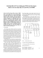
A. Undermodulation Region Sub-net:
For any command angle c/, the duty cycles d), d2, do are
given by (1) for sector 81• Similar duty cycles can be
determined for all six sectors and the phase tum-on duty
cycles can be calculated as [12]:
)
1 3
dA-ON =2+;M' hIO (a
(10)
'
3 M (a )
dB-ON= 21 + ;h20
1
3 M (a )
dC-ON= 2 + ;h30
where
Applying theory of linear modulation within trajectoy, the
fIrst trajectoy has been chosen with M = 0.907:
(9)
.
'
.
'
1[- sin(r13 -a)-sinal
,)_ [- sin(r13 -a)+sinal
hIO (a - [+sin(r13 _ a)+ sinal
[+sin(r13 -a)-sinal
8=I, 6
8= 2
8= 3, 4
8= 5
(11)
*
*
h2o(a\ h3o(a ) are obtained similarly. Then, hIO,2o,3o(a ) have
been used for creating databases which are needed for training
---oo
d;=I-d, -d,
The second one is the bounday of hexagon (2).
Coeficient of modulation is deined as following:
---30
(4)
1= M-M,
M,-M,
---SCO
The duty cycles accordingly [8] are detemined as :
d,=d,' +1(d,"-di)
d,=d,' +1(d,"-d,')
do=d; +1(-d;)
. vermodulation mode 2 (0.952
(5)
f10: tansig; 20: purelin; 30: purelin
O=sqt3)2; bO=1/2
Figure 2.
<
M < 1)
In overmodulation mode 2, the reference vector y*
increases urther up to six-step mode.
Applying theory of linear modulation within trajectory, the
fIrst trajectoy has been chosen with M = 0.952 :
_ 3cosa-sina
d', -
3cosa+sina
d,'=l-d,
d;=0
(6)
The second is divided in two cases:
For 0�a�r16 :
*
undermodulation region Sub-net with one input (a ) and three
0
outputs (hIO' h2o, h30)' The angle step is 1 .
A two-layer network is used for implementing this Sub-net.
The sub-net is obtained by training (supervised) with trainlm
unction - Levenberg -Marquardt algorithm, the acceptable
lSI
for training squared error is 10-4• The number of neurons of
d
n
layer is 10 tansig neurons, the 2 layer has 3 purelin neurons.
So, the total number of neurons is 13 neurons (convergence
obtained for 1077 epochs).
B.
d,"=I;d,"=0;do"=0
(7)
d,"= O;d,"=I;do"=0
(8)
For r16�a�r13 :
Accordingly [8], the duty cycles are described linearly
as following:
Undermodulation region subnet
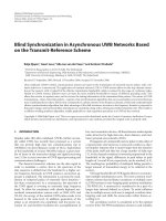
vermodulation model Sub-net
The duty cycles d), d2, do are calculated by (5) for sector 81•
Ater several subtitutions, the duty cycles can be described as :
.(
) [
.
K cosa-sina]
(
)+ '
d, =K,smrl3-a +1-K,sm
rl3-a
.
K,cosa+sma
K,cosa-sina]
[ '
d,= 1 K,cosa-sina
. +1-K,sma+ 1 .
K,cosa+sma
K,cosa+sma
(12)
do=l-d,-d,
where
978-1-4244-9036-3/101$26.00 ©2010 IEEE
2
IFOST
2010 Proceedings
K, =
Kl=3;
3 ·0.907
r
Duty cycles can be determined for all six sectors and the phase
tum-on duty cycles can be calculated similar as (10)-(11) by
subtituting (12).
�+ � [hl1a {a' )+/.h'la {a' )]
= � + � [hl1b (a' )+/.h'lb (a' )]
= � + � [hl1' (a' )+/.h'k (a' )]
dA_oN =
dB_ON
dC_ON
(13)
(1
)
3cosa-sina +
3cosa-sina
/
3cosa+ sina
3cosa+ sina
3cosa-si
n
a
+/ 3cosa-sina 1
d ,3cosa+sina
3cosa+sina
do =0
d1
-1
- For t/6
<
[
]
(16)
a;I3 :
3cosa-sina + 3cosa-sina
d1
/.
3cosa+sina
3cosa + sina
3cosa-sina
3
cosa-si
n
a
+/. ..
d, =1
.3 cosa + sina
3cosa + sina
----
where
-K,s1.O(r/3-a)-I+ K1cosa-si.na
Klcosa+s1Oa'
-K,sin(r/3-a)+1 Klcosa-sina
Klcosa+sina'
.
+ K,s1o(/3
r -a)+ 1 Klcosa-sina
Klcosa+sina'
Kl
.
K,s1O(/3
r -a)-I+ cosa-si.na ,
Klcosa+s1Oa
8=1,6
(17)
(14)
---S2
8=2
8=3,4
--32
8=5
and
---SC2
12:
]2
--S
- A1
u
---31
SC1
Figure 4.
11: tansig; 21: purelin; 31: pure Ii n
Wl=l2; bl=112
Figure 3.
Overnodulation mode 1 region subnet
8=1,6
-I+ K,(sin(r 1 3-a)+sina),
K
cosa-si
n
a
.
.
1
K,(s1O(r/3-a)+s1Oa)+ 1-2.
, 8=2
Klcosa+s1.Oa
h'la (a' ) = I-K,(sin(r/3-a)+sina),
8=3,4
K
cosa-si
n
a
.
.
1
-1+K,(s1O(r/3-a)+s1Oa)+2.
, 8=5
Klcosa+s1.Oa
(15)
*
*
*
*
hllb(a ), h2lb(a ),h11e(a ), h2 1e(a ) are obtained similarly.
*
Then, h11, 211, 11b, 21b, 11e, 21e (a ) have been used for creating
databases which are needed for training overmodulation
'
region Sub-net with one input (a ) and six outputs
(h11a,h2Ia,hllb,h2Ib,hlle,h2Ie)' The angle step is 1 degree.
A two-layer network is used for implementing this Sub-net.
The sub-net is obtained by training (supervised) with trainlm
unction - Levenberg -Marquardt algorithm, the acceptable
sl
for training squared error is 10-4. The number of neurons of 1
d
layer is 20 tansig neurons, the 2n layer has 6 purelin neurons.
So, the total number of neurons is 26 neurons (convergence
obtained for 1016 epochs).
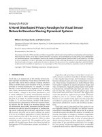
. vermodulation mode 2 Sub-net
The duty cycles in this mode dt. d2, do are given by (9) for
sector 81. Ater several transformations, the duty cycles can be
written as:
- For 0 < a;t/6 :
dB_ON =hi2b (a' ) +/.h"b (a' )
dC_ON =h1"
{a' ) +/.h,,, {a' )
0,
8=1,6
3
cos
a
-si
n
a
1
8=2
cosa+sina'
h'la (a' ) = 0.5,3
8=3,4
3 cosa-sina
8=5
3 cosa+sina
and
(19)
0,
8= 1,6
.3cosa-sina f
1orO : a : f6
3 cosa + sina
3 cosa-sina .or f6<
3cosa+sina'
h'la {a' ) = D,
8=3,4
cosa
-si
n
a
f rO : a : f6
1- 3
.3 cosa + sina o
3 cosa-sina .or f6<
3cosa+sina'
[
[
(20)
8= 2
8=5
*
*
*
*
h2lb(a ), h22b(a ),h2Ie(a ), h22e(a ) are obtained similarly.
*
Then, h2la, 22, 21b, 22b, 21e, 22e (a ) have been used for creating
databases which are needed for raining overmodulation mode
*
2 Sub-net with one input (a ) and six outputs
(h2Ia,h22a,h2Ib,h22b,h2Ie,h22e)' The angle step is 1 degree.
A two-layer network is used for implementing this Sub-net.
The sub-net is obtained by training (supervised) with trainlm
unction - Levenberg -Marquardt algorithm, the acceptable
sl
for training squared error is 10-4• The number of neurons of 1
m
]1
5:
tansig; 8: purel i n
Figure 5.
3
2=I; b2=O
Overnodulation mode 2 region subnet
Duty cycles can be expressed for all six sectors by using (15):
dA_oN =hI2a (a' )+/.h". (a' )
(18)
where
]1
tansig; 22: purelin; 32: purelin
Il calculation subnet
978-1-4244-9037-0/10/$26.00
©2010 IEEE
IFOST
2010 Proceedings
m
6:
!ansig; 9: pure!in
Figure 6.
12 calculation subnet
e.
m-�
eb
eo
7: tansig: (13: purelin; (14: logsig; (15: pU"elin
Figure 7.
Code of modulation mode Sub-net
layer is 20 tansig neurons, the 2nd layer has 6 purelin neurons.
So, the total number of neurons is 26 neurons (convergence
obtained for 200 epochs).
D.
71, 72 calculation Sub-nets
The coeficient 1 1 and 1 2 in overmodulation mode 1 and
mode 2 respectively are given by equation (4). This equation
had been used for generating neural network training data. The
input M is varied rom 0.907 to 0.952 with step of 0.001, he
ouput is 1 1 and varied rom 0.952 to 1 with step of 0.001, the
ouput is 1 2 .
A 2 two-layer network is used for implementing these sub
nets. The sub-net is obtained by training (supervised) with
trainlm unction - Levenberg -Marquardt algorithm, the
acceptable for training squared error is 10-4• The number of
neurons of 1st layer is 1 tansig neurons, the 2nd layer has 1
purelin neurons. So, the total number of neurons is 2 neurons
Convergence is obtained for 57 epochs for 11-subnet and 46
epochs for 12-subnet) (Fig. 5, 6).
.
The input of this subnet is Cm, the ouput is eA, eB, ec (Table
1). (Fig.7)
The sub-net is trained with trainlm unction - Levenberg Mrquardt algorithm, the acceptable for training squared error
1
is 10- 0• The number of neurons of 1st layer is 2 logsig
neurons; the 2nd layer has 3 purelin neurons. So, the total
number of neurons is 5 neurons. Convergence is obtained for
17 epochs.
IV.
SIMULATION OF NN -SVPWM
A SimulinkiMatlab program with the toolbox of neural network is used to train and simulate the complete AN
SVPWM Controller with the above-mentioned sub-nets for
diferent
mode
of
operation:
undermodulation,
overmodulation mode 1,2.
DC source voltage Vd= 400V
1. Case stuy 1:
Modulation index: M = 0.5 when 0 ms ; t ; 40 ms; M =
0.93 when 40 ms;t; 80 ms; M = 0.97 when 80 ms;t;120
ms;M = 1 when 120 ms;t;160 ms.
Figure 8.
Simulation model for NN -SVPWM Controller
Code of modulation mode Sub-net
The purpose of this subnet is to deine the code of
modulation mode:
Undermodulation : Cm = 3
Overmodulation mode 1 : Cm = 1
Overmodulation mode 2 : Cm = 2
The input M is varied rom 0 to 1 with step of 0.001, the
ouput is Cm•
TABLE I
MODE SELECTION CODE
em
eA
I
0
3
2
I
0
eB
ec
I
0
0
0
I
The sub-net is trained with trainlm unction - Levenberg Marquardt algorithm, the acceptable for training squared error
1
is 10- 0• The number of neurons of 1st layer is 15 tansig
neurons; the 2nd layer has 1 purelin neurons. So, the total
number of neurons is 16 neurons. Convergence is obtained for
519 epochs.
. Mode Selection Code Sub-net
This subnet is used for determining which modulation mode
to be choice for generating duty cycles at outputs of AN
SVM-Controller (SA,SB,Sc).
978-1-4244-9036-3/101$26.00 ©2010 IEEE
Figure 9.
Simulation model of Voltage Source Inverter
0
TABLE II
Table of simulation results for nn- controller
Modulation index M
Reference voltage V Ifef, [V]
0.5
0.93
0.97
1
(sixstep)
127.3
236.8
247.0
254.6
Simulated output peak phase
126.7
236.7
246.3
254.6
Tolerance e, [%]
0.471
0.042
0.283
0
1.13
2.15
10.22
26. 2
voltge V INN, [V]
Distortion factor THO, [%]
SImulatIOn results demonstrate the excellent performance
of the proposed AN-SVPWM for VSI, while the good
responses of the output voltages are obtained (ig.l0 - 11,
Table II).
4
IFOST
2010 Proceedings
Phase oltage waeform
ime, (us)
10
Y, I
12
HP, cosp =0.81, 1395 pm (Fig.15)
14
Figure 10. Phase voltage for undermodulation and overmodulation
mode 1,2 region
Figure 13. Data process for
multiplication
Figure 14. Step-by-step NN
design
Figure 11. Line voltage for undermodultion nd overmodulation mode
1,2 regions
V. ANN-SVPWM IMPLEMENTAnON USING FPGA
I. ANN implementation summary
It is important to pay attention to Max-Min value of ANN
parameters. For used FPGA resource reduction, bias and
weights of ANN should to be declared in a speciic range.
ANN has been initialized and trained in Matlab. Next, ANN
parameters have been got and declared in VHDL. ANN is
created step by step with above algorithm for operations.
2. NN application scheme for SVPWM (Fig.12-14)
For SVPWM, ANN is used to calculate ON-OFF time for
six switches when given alpha and modulation factor of
required space vector. A speciic scheme for FPGA program is
presented in Fig.14
Figure 15. Experimental model
Case stuy 1: Undermodulation
1 415094 H2
4.9 U
99.7 or
00
:H1 s.oovw
gÃak
Figure 12.
CH1 f -": n,v
50.3548
;
=
W'Đ'Ơ
VOLTS
I.'IE
VI. EXPEIMENTAL AN-SVPWM
-
Figure 16. Line voltage wave form nd spectrum in case switch
requency is 40kHz, fou=50Hz, M=O.6,Vdc=100V.
SODH�
3B7u
9 ..
0 .r
00
ANN-SVPWM Scheme
Experimental model includes: Kit XUP Virtex II pro of Xilinx;
Capacitor 5600lF, 450V; Driver circuit HCPL-3120; 6-switch
IGBT inverter circuit (Fairchild IGBT G60NlOO 60A, 1000V);
Induction motor has the follows parameters: f = 50 Hz, 3 80V,
5
M 2.SCms
.4
, 'I�
· ;�J ·"· ··· · · · · · · · · · ·
o
,
YObTS
, ,
Figure 17. Phase voltage wave form and spectrum in case switch
requency is 2kHz, fout40Hz, M=O.7, Vdc=100V
978-1-4244-9037-0/101$26.00
©2010 IEEE
IFOST
2010 Proceedings
' 'ri��:
rNxI
YXY:YX:M
���t�
so···
.
.
.
o
1 ... .
3S8 H�
.127 n
99.7 or
results that implementing the proposed method the
undamentals of the output voltages are ensured and the phase
curents maintain symmetrical.
O·
....... __.........._-
1
." _
5
•
MH•.
AlPS
VII.
p
Figure 18. Three- phase current waveforms and spectrum in case
switch requency is 2kHz, fout40Hz, M=O.7, Vdc=100V
Case study 2: Overmodulation mode 1
�r� m
......
o
S rnsJd i v
50V/dlv
•
.
1 4 .•
�.9B l�
718 U
940 .r
··_�_·m.m_._ ..
o·
....
.
... ....
.
_ _
iM
VOLTS
.
-
Figure 19. Line voltage wave form and spectrum in case
switch frequency is 2kHz, fout=50Hz, M=0.94, Vdc=100V.
0.
1 !.�
�:
lD
-� · �I·· mm . . . mm. . . .
�
Figure 20.
o
.
1 ....
19BHz
.ese A
99.3 ' .
'" i i
KF
ACNOWLEDGMENT
The authors grateully acknowledge Vietnamese National
University of Hochiminh City (U) and Network Based
Automation Research Center (NARC) - Ulsan University for
providing excellent supports and facilities.
O·
REFERENCES
.
•
Three- phase current waveforms and spectrum in
-
[1]
1. Holtz "Pulse width modulation for electric power conversion",
[2]
1. O. P. Pinto, B. K. Bose, L. E. B. Silva, M. P. Karmierkowski "A
· �I·· · · · · · · · · · · ·
•
I
1 4'''
398 H:
4n7u
972%00
__'[""
Figure 21. Phase voltage wave form and spectrum in case
Proc.lEEE,vo1.82,pp.l194-1214,Aug. 1994.
Neural Network Based Space Vector PWM Controller for Voltage-Fed
Inverter Induction Motor Drive", IEEE Trans. on Ind. Appl., vol.36, no.
6,NovemberlDecember 2000.
case switch frequency is 2kHz, fou=40Hz, M=0.94,Vdc=100V
o
CONCLUSION
This paper presents the algorithm of ANN implementation
in FPGA for SVPM. The ANN in kit Virtex II pro of Xilinx
operates very well in undemodulation as well as in
overmodulation. The implementation of the ANN-SVPM is
done by simulation and in experiment to serve the practical
production of the cost effective inverters in the ture based on
FPGA.
-
[3]
A. Bakhshai, 1. Espinoza, G. loos, H. lin. "A combined NN and DSP
approach to the implementtion of space vector modulation techniques",
in conf. Rec.IEEE -lAS Annu. Meeting,1996, pp.934-940.
[4]
F. Harashima et aI., "Applications of neural networks to power converter
control",in conf Rec.lEEE -lAS Annu. Meeting,1989, pp.l086-1091.
[5]
M. R. Buhl nd R. D. Lorenz, "Design nd implementation of neural
networks for digital current regulation of inverter drives", in conf
Rec.lEEE -lAS Annu. Meeting,1991, pp.415-423.
switch requency is 2kHz, fout40Hz, M=O.94, Vdc=100V
[6]
Case stuy 3: Overmodulation mode 2
, ...
190Hz
79 U
9S %.
o·
-
Figure 22. Line voltage wave form and spectrum in case
switch requency is 2kHz, fout=50Hz, M=O.985, Vdc=100V.
1 4 .•
1.90HZ
2B7 A
9 ..9 %.
o·
1. W. Song, K. C. Lee, K. B. Cho, 1. S. Won, " An adaptive lening
current controller for ield - oriented controlled induction motor by
neural network",in Proc. IEEE -IECON'91, 1991,pp.469-474.
[7]
M. P. Karmierskowski et aI., " Neural network current control of VS
PWM inverters ",in Proc. IPE'95,1995, pp.1415-1420.
[8]
N.V.Nho, M. 1. Youn, "Two-mode overmodulation in two level VSI
using principle control between limit trajectories", CD-ROM Proc.
PEDS 2003,pp.l274-1279
[9]
1. Holtz, W. Lotzkat, M. Khambadkone, "On continuous control of
PWM inverters in the overmodulation rnge incIudingthe six-step
mode",IEEE Trns. Power Electron. , vol.8, pp.546-553,Oct. 1993.
[10] S. Bolognani, M. Ziglitti, "Novel digital continuous control of SVM
inverters in the overmodulation rnge", IEEE Trans. Ind. Applicat.,
vo1.33,pp.525-530,Mars/ April 1997.
[11] S.Abramik, "Contribution a I'etude du diagnostic de defaillance des
convertisseurs statiques en temps reelle» These du Doctorat,
ENSEEIHT,2003.
[12] Phn Quoc Dzung, Le Minh Phuong, Pham Qung Vinh, Nguyen Van
Figure 23. Three- phase current waveforms and spectrum in case switch
requency is 2kHz,fout=50Hz, M=O.985, Vdc=IOOV
The results of output voltages nd currents are shown in
Fig.16-23. The Fig. 16 shows the value of the undamentals
of the output line-voltage is 4S.9(V) while its theoretical value
is 46.78(V). So, the error of the output line voltage is 1.88%.
In addition too, in the Overmodulation mode 1 (Fig. 19) and
Overmodulation mode 2 (Fig. 22) the voltage erors of
experiment implementation in compare with the theoretical
are 2.03% and 3.77%, respectively. It can be seen rom these
978-1-4244-9036-3/101$26.00 ©2010 IEEE
Nho, Dao Minh Hien, "The Development of Artiicial Neural Network
Space Vector PWM and Diagnostic Controller for Voltage Source
Inverter", 2006 IEEE Power India Conference, New Delhi, India, April
10-12,2006.
[13] Phn Quoc Dzung, Le Minh Phuong, Pham Qung Vinh, "The
Development of Artiicial Neural Network Space Vector PWM for
Four-Switch Three-Phase Inverter",PEDS 2007.
[14] Volnei A.Pedroni, "Circuit Design with VHDL",MIT press,2004.
6