Electrokinetic of soil remediation critical overview
Bạn đang xem bản rút gọn của tài liệu. Xem và tải ngay bản đầy đủ của tài liệu tại đây (1.44 MB, 25 trang )
Ž.
The Science of the Total Environment 289 2002 97᎐121
Electrokinetic soil remediation ᎏ critical overview
Jurate Virkutyte
a,
U
, Mika Sillanpaa
a
, Petri Latostenmaa
b
¨¨
a
Uni¨ersity of Oulu, Water Resources and En¨ironmental Engineering Laboratory, Tutkijantie 1 F 2, 90570 Oulu, Finland
b
¨
Finnish Chemicals Oy, P.O. Box 7, FIN-32741 Aetsa, Finland
¨
Received 28 May 2001; accepted 31 August 2001
Abstract
In recent years, there has been increasing interest in finding new and innovative solutions for the efficient removal
of contaminants from soils to solve groundwater, as well as soil, pollution. The objective of this review is to examine
several alternative soil-remediating technologies, with respect to heavy metal remediation, pointing out their
strengths and drawbacks and placing an emphasis on electrokinetic soil remediation technology. In addition, the
review presents detailed theoretical aspects, design and operational considerations of electrokinetic soil-remediation
variables, which are most important in efficient process application, as well as the advantages over other technologies
and obstacles to overcome. The review discusses possibilities of removing selected heavy metal contaminants from
clay and sandy soils, both saturated and unsaturated. It also gives selected efficiency rates for heavy metal removal,
the dependence of these rates on soil variables, and operational conditions, as well as a cost᎐benefit analysis. Finally,
several emerging in situ electrokinetic soil remediation technologies, such as Lasagna
TM
, Elektro-Klean
TM
, elec-
trobioremediation, etc., are reviewed, and their advantages, disadvantages and possibilities in full-scale commercial
applications are examined. ᮊ 2002 Elsevier Science B.V. All rights reserved.
Keywords: Electrokinetic soil remediation; Heavy metals
1. Introduction
Every year, millions of tonnes of hazardous
waste are generated in the world. Due to ineffi-
cient waste handling techniques and hazardous
waste leakage in the past, thousands of sites were
contaminated by heavy metals, organic com-
U
Corresponding author.
pounds and other hazardous materials, which
made an enormous impact on the quality of
groundwater, soil and associated ecosystems. Dur-
ing the past decades, several new and innovative
solutions for efficient contaminant removal from
soils have been investigated and it is strongly
believed that they will help to solve groundwater
and soil pollution. Despite numerous promising
laboratory experiments, there are not many suc-
cessfully implemented in situ soil-treatment tech-
0048-9697r02r$ - see front matter ᮊ 2002 Elsevier Science B.V. All rights reserved.
Ž.
PII: S 0 0 4 8 - 9 6 9 7 0 1 01027-0
()
J. Virkutyte et al. rThe Science of the Total En
¨ironment 289 2002 97᎐12198
niques yet. Because of uncertainty, lack of ap-
propriate methodology and proven results, many
in situ projects are currently under way. It is
likely that there will not be a single universal in
situ soil-treatment technology. Instead, quite a
large variety of technologies and their combina-
tions suitable for different soil remediation situa-
tions will be developed and implemented.
Although the successful and environmentally
friendly soil treatment technologies have not been
completely investigated and implemented, there
are several techniques which have attracted in-
creased interest among scientists and industry
officials. These are:
ⅷ
Bioremediation ᎏ despite a demonstrated
ability to remove halogenated and non-
halogenated volatiles and semi-volatiles, as
well as pesticides, this technique has failed to
show efficient results in removing heavy met-
als from contaminated soils.
ⅷ
Thermal desorption ᎏ this treats halogenated
and non-halogenated volatiles and semi-vola-
tiles, as well as fuel hydrocarbons and pesti-
cides. It has failed to demonstrate an ability to
remove heavy metals from contaminated soils.
ⅷ
Soil vapour extraction ᎏ there are several
promising results in reducing the volume of
treated heavy metals. Nevertheless, this tech-
nique cannot reduce their toxicity.
ⅷ
Soil washing ᎏ this technique has demon-
strated potential effectiveness in treating
heavy metals in the soil matrix.
ⅷ
Soil flushing ᎏ according to laboratory-scale
experiments, this is efficient in removing heavy
metals from soils, despite the fact that it can-
not reduce their toxicity.
ⅷ
Electrokinetic soil remediation.
As none of the other in situ soil remediation
techniques has demonstrated the efficient re-
moval of heavy metals, there was a necessity to
develop other methods to remediate soil contami-
nated by heavy metals.
Electrokinetic soil remediation is an emerging
technology that has attracted increased interest
among scientists and governmental officials in the
last decade, due to several promising laboratory
and pilot-scale studies and experiments. This
method aims to remove heavy metal contami-
nants from low permeability contaminated soils
under the influence of an applied direct current.
However, regardless of promising results, this
method has its own drawbacks. First of all, the
whole electrokinetic remediation process is highly
dependant on acidic conditions during the appli-
cation, which favours the release of the heavy
metal contaminants into the solution phase. How-
ever, achieving these acidic conditions might be
difficult when the soil buffering capacity is high.
In addition, acidification of soils may not be an
environmentally acceptable method. Second, the
remediation process is a very time-consuming ap-
plication; the overall application time may vary
from several days to even a few years. There are
some other limitations of the proposed technique
that need to be overcome: i.e. the solubility of the
contaminant and its desorption from the soil ma-
trix; low target ion concentration and high non-
target ion concentration; requirement of a con-
ducting pore fluid to mobilise contaminants; and
heterogeneity or anomalies found at sites, such as
large quantities of iron or iron oxides, large rocks
Ž.
or gravel, etc. Sogorka et al., 1998 .
According to the experiments and pilot-scale
studies conducted, metals such as lead, chromium,
cadmium, copper, uranium, mercury and zinc, as
well as polychlorinated biphenyls, phenols,
chlorophenols, toluene, trichlorethane and acetic
acid, are suitable for electrokinetic remediation
and recovery.
2. Theoretical, design and operational
considerations
2.1. Theoretical aspects
The first electrokinetic phenomenon was
observed at the beginning of the 19th Century,
when Reuss applied a direct current to a
Ž
clay᎐water mixture Acar and Alshawabkeh,
.
1993 . However, Helmholtz and Smoluchowski
were the first scientists to propose a theory deal-
ing with the electroosmotic velocity of a fluid and
()
J. Virkutyte et al. rThe Science of the Total En
¨ironment 289 2002 97᎐121 99
the zeta potential under an imposed electric gra-
Ž.Ž .
dient Acar and Alshawabkeh, 1993 . Sibel
Pamukcu and her research group have derived
the following Helmholtz᎐Smoluchowski equation:
Ѩ
Ž.
u s 1
EO
Ѩx
where u is the electroosmotic velocity, is the
EO
dielectric constant of the pore fluid, is the
viscosity of the fluid and ѨrѨ x is the electric
Ž.
gradient Pamukcu and Wittle, 1992 .
When DC electric fields are applied to con-
taminated soil via electrodes placed into the
ground, migration of charged ions occurs. Positive
ions are attracted to the negatively charged cath-
ode, and negative ions move to the positively
charged anode. It has been experimentally proved
that non-ionic species are transported along with
the electroosmosis-induced water flow. The direc-
tion and quantity of contaminant movement is
influenced by the contaminant concentration, soil
type and structure, and the mobility of contami-
nant ions, as well as the interfacial chemistry and
the conductivity of the soil pore water. Electroki-
netic remediation is possible in both saturated
and unsaturated soils.
Electrokinetic soil treatment relies on several
interacting mechanisms, including advection,
which is generated by electroosmotic flow and
externally applied hydraulic gradients, diffusion
of the acid front to the cathode, and the migra-
tion of cations and anions towards the respective
Ž.
electrode Zelina and Rusling, 1999 . The domi-
nant and most important electron transfer reac-
tions that occur at electrodes during the elec-
trokinetic process is the electrolysis of water:
q
Ž.
y
HOª 2H q1r2Ogq2e
22
yy
Ž. Ž.
2H O q2e ª 2OH qHg 2
22
The acid front is carried towards the cathode
by electrical migration, diffusion and advection.
The hydrogen ions produced decrease the pH
near the anode. At the same time, an increase in
the hydroxide ion concentration causes an in-
crease in the pH near the cathode. In order to
solubilise the metal hydroxides and carbonates
formed, or different species adsorbed onto soils
particles, as well as protonate organic functional
groups, there is a necessity to introduce acid into
the soil. However, this acid addition has some
major drawbacks, which greatly influence the ef-
ficiency of the treatment process. The addition of
acid leads to heavy acidification of the contami-
nated soil, and there is no well-established method
for determining the time required for the system
to regain equilibrium.
The main goal of electrokinetic remediation is
to effect the migration of subsurface contami-
nants in an imposed electric field via electro-
osmosis, electromigration and electrophoresis.
These three phenomena can be summarised as
follows:
ⅷ
Electroosmosis is the movement of soil mois-
ture or groundwater from the anode to the
cathode of an electrolytic cell.
ⅷ
Electromigration is the transport of ions and
ion complexes to the electrode of opposite
charge.
ⅷ
Electrophoresis is the transport of charged
particles or colloids under the influence of an
electric field; contaminants bound to mobile
particulate matter can be transported in this
manner.
The phenomena occur when the soil is charged
with low-voltage direct current. The process might
be enhanced through the use of surfactants or
reagents to increase the contaminant removal
rates at the electrodes. Upon their migration to
the electrodes, the contaminants may be removed
by electroplating, precipitationrco-precipitation,
pumping near the electrode, or complexing with
ion exchange resins.
Electromigration takes place when highly solu-
ble ionised inorganic species, including metal
cations, chlorides, nitrates and phosphates, are
present in moist soil environments. Electrokinetic
remediation of soils is a unique method, because
it can remediate even low-permeability soils.
Other mechanisms that greatly affect the elec-
trochemical remediation process are electroosmo-
sis, coupled with sorption, precipitation and disso-
()
J. Virkutyte et al. rThe Science of the Total En
¨ironment 289 2002 97᎐121100
Ž.
lution reactions van Cauwenberghe, 1997 . This
is the reason why all the appropriate processes
should be taken into consideration and investi-
gated before implementation of the technique
can take place.
Once the remediation process is over, extrac-
tion and removal of heavy metal contaminants
are accomplished by electroplating at the elec-
trode, precipitation or co-precipitation at the
electrode, pumping water near the electrode, or
complexing with ion exchange resins. Adsorption
onto the electrode may also be feasible, as some
ionic species will change their valency near the
Ž.
electrode depending on the soil pH , making
Ž
them more likely to adsorb van Cauwenberghe,
.
1997 .
Prediction of THE decontamination time is of
great importance in order to estimate possible
power consumption and to avoid the occurrence
of reverse electroosmotic flow, i.e. from the cath-
Ž
ode to the anode, during the process Baraud et
.
al., 1997, 1998 . The phenomenon of reverse elec-
troosmotic flow is not well understood and should
be further investigated.
Decontamination velocity depends on two
Ž.
parameters Baraud et al., 1997, 1998 :
ⅷ
Contaminant concentration in the soil solu-
tion, which is related to the various possible
Ž
solidrliquid interactions adsorptionrdesorp-
tion, complexation, precipitation, dissolution,
.
etc. and to the speciation of the target species.
ⅷ
Velocity in the pore solution when species are
in the soil solution and not engaged in any
reactions or interactions. The velocity depends
Ž
on different driving forces electric potential
gradient, hydraulic head differences and con-
.
centration gradient and is not closely related
to soil properties, except for the electroosmo-
sis phenomenon.
The success of electrochemical remediation de-
pends on the specific conditions encountered in
the field, including the types and amount of con-
taminant present, soil type, pH and organic con-
Ž.
tent Acar and Alshawabkeh, 1993 .
For in situ conditions, the contaminated site
itself and the immersed electrodes form a type of
electrolytic cell. Usually, the electrokinetic cell
design in laboratory experiments consists of an
open-flow arrangement at the electrodes, which
permits injection of the processing fluid into the
porous medium, with later removal of the con-
Ž
taminated fluid Sogorka et al., 1998; Reddy and
Chinthamreddy, 1999; Reddy et al., 1997, 1999;
.
Zelina and Rusling, 1999 .
It seems that there is a controversy as to where
electrodes should be placed to obtain the most
reliable and efficient results. It is obvious that
imposition of an electrical gradient by having
inert electrodes results in electroosmotic flow to
the cathode. Many authors propose that position-
ing of the electrodes directly into the wet soil
Ž
mass produces the most desirable effect Sims,
1990; Acar and Alshawabkeh, 1993; Reddy et al.,
.
1999; Sogorka et al., 1998 . Through seeking im-
provements in experiments, some researchers tend
to place the electrodes not directly into the wet
soil mass, but into an electrolyte solution, at-
tached to the contaminated soil, or else to use
Ž
different membranes and other materials van
Cauwenberghe, 1997; Baraud et al., 1998; Bena-
.
zon, 1999 . In order to maintain appropriate
process conditions, a cleaning agent or clean wa-
ter may be injected continuously at the anode.
Thus, contaminated water can be removed at the
cathode. Contaminants at the cathode may be
removed by electrodeposition, precipitation or ion
exchange.
Electrodes that are inert to anodic dissolution
should be used during the remediation process.
The most suitable electrodes used for research
purposes include graphite, platinum, gold and sil-
ver. However, for pilot studies, it is more ap-
propriate to use much cheaper, although reliable,
titanium, stainless steel, or even plastic elec-
trodes. Using inert electrodes, the electrode reac-
tions will produce H
q
ions and oxygen gas at the
anode and OH
y
ions and hydrogen gas at the
cathode, which means that if pH is not controlled,
an acid front will be propagated into the soil
pores from the anode and a base front will move
out from the cathode.
It has been proved by experiments that when
heavy metals enter into basic conditions, they
adsorb to soil particles or precipitate as hydrox-
()
J. Virkutyte et al. rThe Science of the Total En
¨ironment 289 2002 97᎐121 101
ides, oxyhydroxides, etc., and in acidic conditions,
those ions desorb, solubilise and migrate.
Another important parameter in the electroki-
netic soil-remediation technique is the conductiv-
ity, since this, together with soil and pore fluid,
affects the electroosmotic flow rate.
The conductivity of soil depends on the concen-
tration and the mobility of the ions present, i.e.
contaminant removal efficiencies decrease with a
Ž
reduction in contaminant concentration Reddy
et al., 1997, 1999; Reddy and Chinthamreddy,
.
1999; Zelina and Rusling, 1999 . This is due to
hydrogen ion exchange with cationic contami-
nants on the soil surface, with release of the
contaminants. As the contaminant is removed,
the hydrogen ion concentration in the pore fluid
increases, resulting in an increasing fraction of
the current being carried by the hydrogen ions
rather than by the cationic contaminants.
It is possible to conclude that the variables
which have impact on the efficiency of removing
contaminants from soils are:
ⅷ
Chemical processes at the electrodes;
ⅷ
Water content of the soil;
ⅷ
Soil type and structure;
ⅷ
Saturation of the soil;
ⅷ
pH and pH gradients;
ⅷ
Type and concentration of chemicals in the
soil;
ⅷ
Applied current density; and
ⅷ
Sample conditioning.
In addition, insoluble organics, such as heavy
hydrocarbons, are essentially not ionised, and the
soils in contact with them are not charged. The
removal of insoluble organics by electric field is
limited to their movement out of the soil by
electroosmotic purging of the liquid, either with
water and surfactant to solubilise the compounds,
or by pushing the compounds ahead of a water
Ž.
front Probstein and Hicks, 1993 .
Ionic migration is the movement of ions sub-
jected to an applied DC electric field. Electromi-
Ž
gration rates in the subsurface depend upon van
.
Cauwenberghe, 1997 :
ⅷ
Soil porewater current density;
ⅷ
Grain size;
ⅷ
Ionic mobility;
ⅷ
Contaminant concentration; and
ⅷ
Total ionic concentration.
The process efficiency is not as dependent on
the fluid permeability of soil as it is on the pore-
water electrical conductivity and path length
Ž.
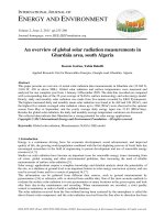
Fig. 1. Electroosmosis and electromigration of ions adapted from Acar et al., 1994, 1996; Acar and Alshawabkeh, 1996 .
()
J. Virkutyte et al. rThe Science of the Total En
¨ironment 289 2002 97᎐121102
through the soil, both of which are a function of
the soil moisture content. As electromigration
does not depend on the pore size, it is equally
Ž
applicable to coarse and fine-grained soils van
.
Cauwenberghe, 1997 .
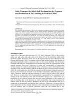
Electroosmosis in water-saturated soil is the
movement of water relative to the soil under the
influence of an imposed electric gradient. When
there is direct current applied across the porous
media filled with liquid, the liquid moves relative
to the stationary charged solid surface. When the
surface is negatively charged, liquid flows to the
Ž.
cathode. Acar et al. 1994, 1996 have conducted
numerous experiments and found that this process
Ž.
works well in wet i.e. water-saturated fine-
grained soils and can be used to remove soluble
pollutants, even if they are not ionic. The dis-
solved neutral molecules simply go with the flow.
Fig. 1 shows a schematic representation of this
process.
An excess negative surface charge exists in all
kinds of soil. For example, many clays are anionic,
colloidal poly-electrolytes. The surface charge
density increases in the following order: sand-
silt - kaolinite - illite - montmorillonite. Injec-
tion of clean fluid, or simply clean water, at the
anode can improve the efficiency of pollutant
removal. For example, such a flushing technique
using electroosmosis has been developed for the
removal of benzene, toluene, trichlorethane and
m-xylene from saturated clay.
According to that stated above, the main fac-
tors affecting the electroosmotic transport of con-
taminants in the soil system are as follows:
ⅷ
Mobility and hydration of the ions and charged
particles within the soil moisture;
ⅷ
Ion concentration;
ⅷ
Dielectric constant, depending on the amount
of organic and inorganic particles in the pore
solution; and
ⅷ
Temperature.
Most soil particle surfaces are negatively
charged as a result of isomorphous substitution
Ž
and the presence of broken bonds Yeung et al.,
.
1997 .
Experiments have determined the dependence
of the zeta potential of most charged particles on
solution pH, ionic strength, types of ionic species,
Ž
temperature and type of clay minerals Vane and
.
Zang, 1997 . For water-saturated silts and clays,
the zeta potential is typically negative, with values
measured in the 10᎐100-mV range.
However, if ions produced in the electrolysis of
water are not removed or neutralised, they lower
the pH at the anode and increase it at the cath-
ode, accompanied by the propagation of an acid
front into the soil pores from the anode and a
base front from the cathode. This process can
Ž
significantly effect the soil zeta potential drop in
.
zeta potential , as well as the solubility, ionic state
and charge, level of adsorption of the contami-
Ž.
nant, etc. Yeung et al., 1997 .
In addition, different initial metal concentra-
tions and sorption capacity of the soil may pro-
duce soil surfaces that are less negative, which at
the same time may become positive at a pH of
approximately the original zero-point charge
Ž.
Yeung et al., 1997 . Similarly, chemisorption of
anions makes the surface more negative.
Electroosmotic flow from the anode to the
cathode promotes the development of a low-pH
environment in the soil. This low-pH environment
inhibits most metallic contaminants from being
sorbed onto soil particle surfaces and favours the
formation of soluble compounds. Thus, electro-
osmotic flow from the anode to cathode, resulting
from the existence of a negative zeta potential,
enables the removal of heavy metal contaminants
by the electrokinetic remediation process.
The pH of the soil should be maintained low
enough to keep all contaminants in the dissolved
phase. Nevertheless, when the pH becomes too
low, the polarity of the zeta potential changes and
Ž
reversed electroosmotic flow i.e. from the cath-
.
ode to the anode may occur. In order to achieve
efficient results in removing contaminants from
soils, it is necessary to maintain a pH low enough
pH to keep metal contaminants in the dissolved
phase and high enough to maintain a negative
Ž.
zeta potential Yeung et al., 1997 . Despite this
apparently easily implemented theory, simultane-
ous maintenance of a negative zeta potential and
()
J. Virkutyte et al. rThe Science of the Total En
¨ironment 289 2002 97᎐121 103
dissolved metal contaminants remains the great-
est obstacle in the successful implementation of
the electrokinetic soil remediation process.
2.2. Design considerations
In order to obtain efficient and reliable results,
electrokinetic remediation of soil should be im-
plemented under steady-state conditions. It is
obvious that during the remediation process, other
reactions, such as transport and sorption, and
precipitation and dissolution reactions, occur and
affect the remediation process.
There have been numerous indications of the
importance of heat and gas generation at elec-
trodes, the sorption of contaminants onto soil
particle surfaces and the precipitation of contami-
nants in the electrokinetic remediation process
Ž
Acar and Alshawabkeh, 1993; Lageman, 1993;
.
Zelina and Rusling, 1999 . These processes should
be further investigated, because it is believed that
they may weaken the removal efficiency for heavy
metal contaminants. It is reported that different
physicochemical properties of the soil may influ-
ence the removal rates of heavy metal contami-
nants, due to changed pH values, hydrolysis, and
oxidation and reduction reaction patterns.
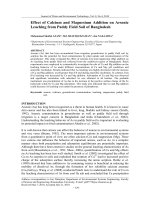
In order to enhance the electrokinetic remedia-
tion process, several authors recommend the use
of a multiple anode system, which is shown in Fig.
2.
2.3. Operational considerations
As there are several experimental techniques
to remediate coarse-grained soils, in situ elec-
trokinetic treatment has been developed for con-
taminants in low-permeability soils. Electrokinet-
ics is applicable in zones of low hydraulic conduc-
tivity, particularly with a high clay content.
Contaminants affected by electrokinetic
processes include:
ⅷ
Heavy metals;
Ž
ⅷ
Radioactive species Cs , Sr , Co , ura-
137 90 60
.
nium ;
Ž.
ⅷ
Toxic anions nitrates and sulfates ;
Ž.
ⅷ
Dense, non-aqueous-phase liquids DNAPLs ;
Fig. 2. Multiple anodes system US EPA, 1998.
ⅷ
Cyanides;
Ž
ⅷ
Petroleum hydrocarbons diesel fuel, gasoline,
.
kerosene and lubricating oils ;
ⅷ
Explosives;
ⅷ
Mixed organicrionic contaminants;
ⅷ
Halogenated hydrocarbons;
ⅷ
Non-halogenated pollutants; and
ⅷ
Polynuclear aromatic hydrocarbons.
Heavy metal interactions in the soil solution
Ž
are governed by several processes, such as Sims,
.
1990 :
ⅷ
Inorganicrorganic complexation;
ⅷ
Acid᎐base reactions;
ⅷ
Redox reactions;
ⅷ
Precipitationrdissolution reactions; and
ⅷ
Interfacial reactions.
The choice of appropriate soil for electroki-
netic remediation process should be made with
extreme caution and possible soil pre-treatment
experiments should be carried out.
Soils that may be used for the electrokinetic
Ž.
remediation process should have Sims, 1990 :
ⅷ
Low hydraulic conductivity;
Ž
ⅷ
Water-soluble contaminants if there are any
poorly soluble contaminants, it may be essen-
.
tial to add solubility-enhancing reagents ; and
()
J. Virkutyte et al. rThe Science of the Total En
¨ironment 289 2002 97᎐121104
ⅷ
Relatively low concentrations of ionic materi-
als in the water.
It is reported that with applied electric fields,
the most suitable soils for heavy metal remedia-
Ž.
tion are kaolinite, clay and sand Sims, 1990 . As
recommended, clay has low hydraulic conductiv-
ity, reducing redox potential, slightly alkaline pH
Ž
which is suitable for the remediation of several
.
heavy metal contaminants , high cation exchange
capacity and high plasticity. Under normal condi-
tions, migration of ions is very slow, but is en-
hanced by electrical fields or hydraulic pressure.
The highest degree of removal of heavy metals
Ž.
over 90% of the initial contaminant has been
achieved for clayey, low-permeability soils,
whereas for porous, high-permeability soils, such
as peat, the degree of removal was only 65%
Ž.
Chilingar et al., 1997 . Laboratory results showed
that electrokinetic purging of acetate and phenol
from saturated kaoline clay resulted in greater
than 94% removal of the initial contaminants.
However, this methodology needs to be further
investigated, because phenol has been reported to
be toxic to humans and the environment.
3. Removal of metals
If heavy metal contaminants in the soil are in
ionic forms, they are attracted by the static elec-
trical force of negatively charged soil colloids.
The attraction of metal ions to the soil colloids
primarily depends on the soil electronegativity
Ž
and the dissociation energy of ions Sah and
.
Chen, 1998 . If there are appropriate pH condi-
tions, heavy metals are likely to be adsorbed onto
the negatively charged soil particles. The main
sorption mechanisms include adsorption andror
ion exchange. Desorption of cationic species from
clay surfaces is essential in extraction of species
from fine-grained deposits with high cation-
exchange capacity.
As Acar and his research group have indicated
Ž
Acar and Alshawabkeh, 1993, 1996; Acar et al.,
.
1994, 1996 , the sorption mechanisms depend on
the surface charge density of the clay mineral, the
characteristics and concentration of the cationic
species, and the presence of organic matter and
carbonates in the soil. The mechanism is also
significantly dependent on the pore fluid pH. The
higher the content of carbonates and organic
material in soils, the lower the heavy metal re-
moval efficiency, which is why the former should
be further investigated and taken into the con-
sideration.
During numerous experiments, a decrease in
Ž
current density was observed Acar and Al-
shawabkeh, 1993, 1996; Acar et al., 1994, 1996;
.
Sah and Chen, 1998 . The possible reasons might
be as follows:
Activation polarisation: during the electroki-
Ž
netic remediation process, gaseous bubbles O
2
.
and H cover the electrodes. These bubbles
2
are good insulators and reduce the electrical
conductivity, subsequently reducing the cur-
rent.
Resistance polarisation: after the electrokinetic
remediation process, a white layer was observed
on the cathode surface. This layer may be the
insoluble salt and other impurities that were
not only attracted to the cathode, but also
inhibited the conductivity, with a subsequent
decrease in current.
Concentration polarisation: the H
q
ions gener-
ated at the anode are attracted to the cathode
and the OH
y
ions generated at the cathode
are attracted to the anode. If acid and alkaline
conditions are not neutralised, the current also
drops.
It is possible to conclude that soil containing
heavy metal contaminants influences the conduc-
tivity.
Interaction of the pollutants with the soil also
affects the remediation process. In order to in-
crease the solubility of complexes formed, or to
improve electromigration characteristics of speci-
fic heavy metal contaminants, an enhancement
solution may be added to the soil matrix.
Sometimes electroosmotic flow rates are too
low, and it may be necessary to flush the elec-
trodes with a cleaning agent, or simply clean tap
Ž.
water Probstein and Hicks, 1993 . In addition,
the electrode may be surrounded by ion-exchange
()
J. Virkutyte et al. rThe Science of the Total En
¨ironment 289 2002 97᎐121 105
material to trap the contaminant and prevent its
precipitation. It is essential to know the buffering
capacity of the soil in order to alter the pH with
suitable solutions or clean water. Many ground-
waters contain high concentrations of bicarbon-
ates, which consume added hydrogen ions to form
carbonic acid, or hydroxyl ions to form carbonate
ions. It is vital to draw attention to the limited
solubility of metal carbonates, as well as the need
for evaluation of sulfide, sulfate, chlor-
ide and ammonia effects, which may occur when
these compounds are introduced into the soil
Ž
system during the remediation process Probstein
.
and Hicks, 1993 .
New alternatives have been suggested for the
remediation of heavy metals from soils without
Ž
having low pH conditions Probstein and Hicks,
.
1993 . When the metal enters the region of high
pH near the cathode, it may adsorb onto the soil,
precipitate, or form hydroxy complexes. At higher
pH values, the solubility increases because of the
increasing stability of soluble hydroxy complexes.
Despite favourable soluble complexes, the disso-
lution process may be time-consuming and too
slow to be successfully implemented.
Concerning the process of transport of con-
taminants and their derivatives, two major pheno-
Ž.
mena were indicated Chilingar et al., 1997 :
1. The flow of contaminant solution through a
solid matrix due to Darcy’s law and electroki-
netics; and
2. Spatial redistribution of dissolved substances
with respect to the moving liquid due to the
diffusion and migration of charged particles.
The total movement of the matter of the con-
taminant solution in the DC electric field can be
expressed as the sum of four components
Ž.
Chilingar et al., 1997 :
ⅷ
The hydrodynamic flow of liquids driven by
the pressure gradient;
ⅷ
The electrokinetic flow of fluids due to inter-
action of the double layer with the DC field;
ⅷ
The diffusion of components dissolved in the
flowing solution; and
ⅷ
The migration of ions inside moving fluids due
to the attraction of charged particles to the
electrodes.
The very questionable concept that removal of
heavy metals in the direct current field is effective
was also expressed, because electromigration of
ions is rapid and does not depend on the zeta
potential. In order to prove or disapprove this,
further investigations of this concept should be
carried out. Despite some disagreements, it was
agreed that in order to obtain efficient and reli-
able results and control the remediation process,
there is a need to provide continuous control of
Ž
the pH in the vicinity of the electrodes Acar and
Alshawabkeh, 1993, 1996; Acar et al., 1994, 1996;
.
Chilingar et al., 1997 . One possible way to achieve
this is periodic rinsing of the cathode with fresh
water.
Experiments have proved that electrical field
application in situ leads to an increase in temper-
ature, which in turn reduces the viscosity of hy-
Ž
drocarbon-containing fluids Chilingar et al.,
.
1997 . The reduction in fluid viscosity leads to an
increase in the total flow rate.
Ž.
It is reported Chilingar et al., 1997 that in
order to accelerate the fluid transport in situ,
electrical properties of soils, such as electrical
resistivity and the ionisation rate of the flowing
fluids that can affect the total rate flow, should
consider. In an applied DC field, some soil types
showed an increase in their hydraulic permeabil-
ity, which allows us to conclude that direct cur-
rent may accelerate fluid transport. However, this
method is not applicable to some clays, because
under the DC field, those clays become amor-
phous. It is possible to avoid such a transforma-
tion if interlayer clay water is trapped and is not
able to leave the system.
From the numerous laboratory and field experi-
ments and studies conducted, it is possible to
conclude that migration rates of heavy metal ions
Ž.
i.e. removal efficiencies are highly dependent on
soil moisture content, soil grain size, ionic mobil-
ity, pore water amount, current density and con-
Ž
taminant concentration Acar and Alshawabkeh,
1993, 1996; Acar et al., 1994, 1996; Chilingar et
.
al., 1997; Sah and Chen, 1998 . Also, in order to
assure the efficient and successful heavy metal
()
J. Virkutyte et al. rThe Science of the Total En
¨ironment 289 2002 97᎐121106
removal from soils, one of the main drawbacks of
this process must be solved, which is premature
precipitation of metal species close to the cathode
compartment.
3.1. Limitations of the technique
The removal of heavy metals from soils using
electrokinetic remediation has some limitations,
which have been widely discussed among many
scientists and researchers. For example, the sur-
face of the electrode attracts the gas generated
from the electrolytic dissociation process and in-
creases the resistance, which significantly slows
Ž
down the remediation process Sah and Chen,
.
1998 . It is obvious that soil resistance is lower in
the earlier stages of the electrokinetic process,
and therefore a lower input voltage is required.
When the electrokinetic process continues, gas
bubbles from electrolytic dissociation cover the
whole cathode surface and the resistance in-
creases. To continue the soil remediation process,
the input voltage must be increased to maintain
the same current, which also increases the voltage
gradient. OH
y
ion that are formed react with
cations and form a sediment, which plugs the
spacing between soil particles, subsequently hin-
dering the electrical current and decreasing the
diffusive flow over time when the voltage is ap-
Ž.
plied Sah and Chen, 1998 .
3.2. Enhancement and conditioning
To overcome the premature precipitation of
ionic species, Acar and his research group have
recommended using different enhancement tech-
niques to remove or to avoid these precipitates in
the cathode compartment. Efficient techniques
should have the following characteristics:
ⅷ
The precipitate should be solubilised andror
precipitation should be avoided.
ⅷ
Ionic conductivity across the specimen should
not increase excessively in a short period of
time to avoid a premature decrease in the
electroosmotic transport.
ⅷ
The cathode reaction should possibly be de-
polarised to avoid the generation of hydroxide
and its transport into the specimen.
ⅷ
Depolarisation will decrease the electrical po-
tential difference across the electrodes, which
would result in lower energy consumption.
ⅷ
If any chemical is used, the precipitate of the
metal with the new chemical should be per-
fectly soluble within the pH range attained.
ⅷ
Any special chemicals introduced should not
result in any increase in toxic residue in the
soil mass.
ⅷ
The cost efficiency of the process should be
maintained when the cost of enhancement is
included.
It is obvious that an enhancement fluid in-
creases the efficiency of contaminated soil treat-
ment; however, there is a lack of data which
would clarify further soil and contaminant inter-
actions in the presence of this fluid.
Ž.
As a depolariser i.e. enhancement fluid in the
cathode compartment, it is possible to use a low
Ž
concentration of hydrochloric or acetic acid Acar
and Alshawabkeh, 1993, 1996; Acar et al., 1994,
.
1996 . The main concern with hydrochloric acid
as the depolariser is that due to electrolysis, the
chlorine gas formed may reach the anode, as well
as groundwater, and increase its contamination.
Acetic acid is environmentally safe and it does
not fully dissociate. In addition, most acetate salts
are soluble, and therefore acetic acid is preferred
in the process.
The anode reaction should also be depolarised,
because of the dissolution and release of silica,
alumina and heavy metals associated with the clay
mineral sheets over long exposure to protons
Ž
Acar and Alshawabkeh, 1993, 1996; Acar et al.,
.
1994, 1996 .
In order to accomplish both tasks successfully,
it is better to use calcium hydroxide as the en-
hancement fluid to depolarise the anode reaction,
and hydrochloric acid as the enhancement fluid to
depolarise the cathode reaction.
The use of an enhancement fluid should be
()
J. Virkutyte et al. rThe Science of the Total En
¨ironment 289 2002 97᎐121 107
Ž
examined with extreme care to prevent Yeung et
.
al., 1997 :
ⅷ
The introduction of a secondary contaminant
into the subsurface;
ⅷ
The generation of waste products or by-prod-
ucts as a result of electrochemical reactions;
and
ⅷ
The injection of an inappropriate enhance-
ment fluid that will aggravate the existing con-
tamination problem.
4. Electrokinetic soil remediation processes
4.1. Remo
¨al of hea¨y metals using cation-selecti¨e
membrane
In alkaline medium, heavy metals are likely to
be adsorbed onto the soil particles and form
insoluble precipitates. The high pH region in clos-
est proximity to the cathode is the main obstacle
Ž
to heavy metal removal Acar and Alshawabkeh,
1993, 1996; Acar et al., 1994, 1996; Li et al., 1997;
Li and Neretnieks, 1998; Li and Li, 2000; Yeung
.
et al., 1997 . However, the latest experimental
studies show that it is possible to deal with the
Ž
pH impact Li et al., 1997; Li and Neretnieks,
.
1998; Li and Li, 2000 . A conductive solution,
which simulates the groundwater conditions, was
placed between the cathode and the soil to be
treated. However, the length of conductive solu-
tion must be at least twice the length of the
treated soil, which may be impossible to imple-
ment at a site. In addition, the solution has to be
placed in a special container, which would sig-
nificantly increase the costs of the overall remedi-
ation process. The pH buffer capacity, cation
exchange capacity of the medium, and interac-
tions of the solution with the soil may affect the
speed of the advancement of the acidic and the
Ž
basic fronts and the location of the pH jump Li
.
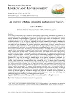
and Li, 2000 . In order to overcome these obsta-
cles, a new method was proposed which should
significantly improve the overall remediation
process. To reduce the relative length or volume
of the water in the system, a cation-selective
Ž.
Fig. 3. Electrokinetic cell with cation-selective membrane adapted from Li and Neretnieks, 1998; Li et al., 1997; Li and Li, 2000 .
()
J. Virkutyte et al. rThe Science of the Total En
¨ironment 289 2002 97᎐121108
Ž
membrane is placed in front of the cathode Li et
al., 1997; Li and Neretnieks, 1998; Li and Li,
.Ž .
2000 Fig. 3 .
Due to an applied electric current, ions move
to the electrodes, according to their charges. The
cation-selective membrane, placed between the
soil and cathode, allows cations and very few
anions to pass through it. This is why almost all
the hydroxyl ions produced at the cathode remain
on the cathodic side of the membrane. The hy-
drogen ions generated at the anode move through
the soil and into the membrane. The basic front
cannot pass through the membrane, where it
meets the acidic front. The main pH changes
Ž
occur near the membrane Li et al., 1997; Li and
.
Neretnieks, 1998; Li and Li, 2000 . It is possible
that the membrane determines the pH jump and
may control the cathode solution volume. A
cation-selective membrane maintains the low soil
pH during the remediation process and signifi-
cantly reduces the length of the conductive solu-
tion required. Hence, the proposed electrokinetic
cell consist of the treated soil, a conductive solu-
tion, which is placed between the soil and the
membrane, and the cathode compartment with
electrolyte solution, which is between the mem-
brane and cathode. After numerous experiments,
it has been observed that the smaller the volume
of conductive solution, the higher the pH will be
and the larger will be the leakage of the anions
Ž
through it Li et al., 1997; Li and Neretnieks,
.
1998; Li and Li, 2000 .
However, a small amount of anions passing
through the membrane may be favourable for the
remediation process. Precipitation decreases the
remediation time, because this reduces the con-
Ž
centration of heavy metals in the liquid phase Li
.
and Li, 2000 . At the same time, back-diffusion of
heavy metals is greatly reduced, since the concen-
tration of heavy metals near the membrane does
not exceed the solubility of the metals. It has
been proved by experiments that precipitation
decreases the electrical energy consumption, be-
cause the potential drop between the electrodes
and the remediation time are proportional to the
Ž
distance between the electrodes Li et al., 1997;
.
Li and Neretnieks, 1998; Li and Li, 2000 .
4.2. Remo
¨al of hea¨y metals using surfactant-coated
ceramic casings
For many years, the main emphasis of elec-
trokinetic soil remediation was on saturated,
fine-grained soils and clays, which led to the mis-
conception that electrokinetics was not suitable
for unsaturated, sandy soils. Laboratory experi-
ments proved that with appropriate technology
and well-designed methods, it is possible to reme-
diate heavy metals from unsaturated and sandy
Ž.
soils Mattson and Lindgren, 1995 . The treat-
ment of unsaturated soils has several limitations.
The electrical conductivity of soil depends on the
Ž.
moisture content Mattson and Lindgren, 1995 .
During electroosmotic migration through the soil,
the water content near the anode is reduced. As
the moisture content decreases, the soil conduc-
tivity becomes too low for the electrokinetic re-
mediation application. In order to control the
hydraulic flux of water in the treated soil, the use
of porous ceramic castings has been proposed.
During the application, it should be remembered
that the direction of electroosmotic flow in porous
ceramic media has a strong influence on the
amount of water being added to the soil from the
ceramic castings. Anode ceramic casting would be
suitable for long-term electrokinetic remediation
processes if it was ensured that electroosmotic
flow occurred from the surrounding soil towards
Ž
the interior of the anode casting Mattson and
.
Lindgren, 1995 . As efficient electrokinetic reme-
diation in unsaturated soils depends on the water
amount at the anode, there is a necessity to
continuously inject water during the whole reme-
diation process. Despite the addition of water, it
is important to maintain unsaturated conditions
in the soil, because excess water may cause satu-
rated conditions and contaminants will be able to
migrate into the deeper layers of the soil.
A number of experiments with an anode cer-
amic casting were conducted and it was proved
that it is possible to remove heavy metal contami-
nants from unsaturated, sandy soils using the
Ž
electrokinetic remediation technique Mattson
.
and Lindgren, 1995 .
First of all a laboratory cell was designed and
constructed, which consisted of a plastic con-
()
J. Virkutyte et al. rThe Science of the Total En
¨ironment 289 2002 97᎐121 109
tainer filled with buffering solution. The polyvinyl
chloride plate glued to the bottom of the con-
tainer, the porous ceramic castings, woven wire
cathode and graphite anode are shown in Fig. 4.
The most suitable buffering solution for this ex-
periment is a phosphate solution with a pH of 6
Ž.
Mattson and Lindgren, 1995 . To overcome the
hydraulic counterflow, the experiment should only
be conducted until the fluid level difference
between the inner and outer reservoirs becomes
Ž.
) 1 cm Mattson and Lindgren, 1995 .
After laboratory experiments, a number of field
studies were conducted and the initial results
obtained are very promising. It is possible to state
that the use of anode ceramic casting may sig-
nificantly improve the application of electroki-
netic remediation in unsaturated soil media.
4.3. Lasagna
TM
process
In 1995, a novel integrated method for in situ
electrokinetic remediation of soils, called
Lasagna
TM
, was developed and implemented at
the Paducah site, in Kentucky, USA. This tech-
nology is useful for removing heavy metal con-
taminants from heterogeneous, low-permeability
Ž.
soils Ho et al., 1997, 1999 .
In brief, the Lasagna
TM
process contains the
following concepts:
ⅷ
The creation of several permeable ‘treatment’
zones in close proximity through the whole
soil matrix by adding sorbents, catalytic
reagents, buffering solutions, oxidising agents,
etc.
ⅷ
Application of an electric current in order to
transport contaminants into the ‘treatment’
zones created.
The Lasagna
TM
process has several advantages
in comparison to other techniques. First, it is
possible to recycle the cathode effluent by aiming
it back to the anode compartment, which would
favour neutralising of the pH and simplify water
management. In addition, the fluid flow may be
Ž
reversed by simply switching the polarity Ho et
.
al., 1999 . The switching of polarity promotes
multiple contaminant passes through the ‘treat-
ment’ zones and helps to diminish the possibility
of non-uniform potential and pH jumps in the soil
system.
Two schematic Lasagna
TM
model configura-
Ž.
tions were suggested: horizontal Fig. 5 and verti-
Ž.
cal Ho et al., 1999 .
The process was called ‘Lasagna’ due to the
layering of treatment zones between the elec-
trodes. The formation of horizontal fractures in
over-consolidating clays due to the horizontal
electrodes and vertical pressuring system make
this method especially effective in removing con-
Ž
taminants from deeper layers of the soil Ho et
Ž.
Fig. 4. Electrokinetic cell with ceramic castings Mattson and Lindgren, 1995 .
()
J. Virkutyte et al. rThe Science of the Total En
¨ironment 289 2002 97᎐121110
TM
Ž.
Fig. 5. Horizontal Lasagna configuration adapted from Ho et al., 1999 .
.
al., 1999 . In addition, for shallow contamination
which does not exceed 15 m and in not over-con-
solidated soils, the vertical treatment configura-
Ž.Ž.
tion is more appropriate Ho et al., 1997 Fig. 6 .
Accordingtolaboratoryexperimentsand
promising pilot-scale studies at the Paducah site
in Kentucky, Lasagna
TM
technology may become
one of the most widely used electrokinetic reme-
diation technologies for removing heavy metal
contaminants from various soils. Nevertheless,
there are several technological and other limita-
tions, which should be improved for future stud-
ies. It is obvious that Lasagna
TM
technology is
potentially capable of treating multiple contami-
TM
Ž
Fig. 6. Vertical Lasagna configuration adapted from Ho et
.
al., 1997 .
nants in clay and laden soils, but additional exper-
iments and studies should be conducted in order
to assure that the treatment process is compatible
for individual contaminants. In addition, one of
the biggest technology drawbacks is the entrap-
ment of gases formed by electrolysis and the
assurance of good electrical contact to the elec-
trodes. To increase the Lasagna
TM
process effi-
ciency, there were attempts to implement biore-
mediation in ‘treatment’ zones. It is believed that
bioremediation together with electrokinetic reme-
diation may significantly increase the overall re-
moval of heavy metals, as well as other contami-
nants, from clays and other soils.
4.4. Electro-Klean
TM
electrical separation
Electro-Klean
TM
technology is applied in situ,
as well as ex situ, in Louisiana, USA. This is a
new methodology, which is used to remove heavy
metals, radionuclides and specific volatile organic
contaminants from saturated and unsaturated
sands, silts, fine-grained clays and sediments. This
technology uses two electrodes to apply DC di-
Ž
rectly into the contaminated soil mass van
.
Cauwenberghe, 1997 . In order to improve the
remediation efficiency, enhancement fluids,
mostly acids, are added into the soil. The main
limitation of this technique is the high buffering
()
J. Virkutyte et al. rThe Science of the Total En
¨ironment 289 2002 97᎐121 111
capacity of the soils and different coexisting
chemicals and their concentrations.
4.5. Electrokinetic bioremediation
Electrokinetic bioremediation technology is de-
signed to activate microbes and other micro-
organisms present in soils by the use of selected
nutrients to promote the growth, reproduction
and metabolism of micro-organisms capable of
Ž
transforming organic contaminants in soil van
.
Cauwenberghe, 1997 . Nutrients reach the or-
ganic contaminants by specially applied bioelec-
tric technology. It is believed that this technology
may be very successful in the future, because it
does not require an external microbial population
to be added into the soil system. In addition,
nutrients may be uniformly dispersed over the
contaminated soil or directed to a specific loca-
Ž.
tion van Cauwenberghe, 1997 and the method
avoids the problems associated with transport of
Ž
micro-organisms through fine-grained soils Fig.
.
7.
Despite promising results, this technology has
some major limitations. Sometimes the concen-
tration of organic pollutant exceeds the toxic limit
for the microbial population and micro-organisms
die. Simultaneous bioremediation of various or-
ganic contaminants may produce by-products,
which are highly toxic to micro-organisms. Those
by-products may significantly inhibit the bioreme-
diation rates.
4.6. Electrochemical geooxidation
Electrochemical geooxidation is used in Ger-
many to remediate soil and water contaminated
Ž
with organic and inorganic compounds van
.
Cauwenberghe, 1997 . The in situ process in-
volves the application of an electrical current to
probes driven into the ground. The applied cur-
rent creates favourable conditions for oxidation᎐
reduction reactions, which lead to the immobilisa-
tion of inorganic contaminants in the soil or
groundwater matrix between the electrode loca-
tions. The main advantage of this technology is
that there is no need to use catalysts for the
oxidation᎐reduction reactions, because in almost
all soils, natural catalysts, such as iron, magne-
sium, titanium and elemental carbon, are present.
The limitations of this technology are the very
long remediation time and the lack of proven
results.
4.7. Electrochemical ion exchange
This technology employs a series of electrodes,
placed in porous castings, which are supplied with
circulating electrolytes. During the remediation
process, ion contaminants are captured in these
Ž.
Fig. 7. Electrokinetic bioremediation according to Thevanayagam and Rishindran, 1998 .
()
J. Virkutyte et al. rThe Science of the Total En
¨ironment 289 2002 97᎐121112
electrolytes and pumped to the surface, where
they are passed through an electrochemical ion
Ž.
exchanger van Cauwenberghe, 1997 . This
method is used to remove heavy metals, halides
and specific organic species from different types
of soils. The most important limitation of this
technology is that it is a very expensive procedure
for cleaning effluents containing low levels of
contaminants.
4.8. Electrosorb
TM
Electrosorb
TM
technology is mostly used in
Louisiana, USA, and uses cylindrical electrodes
coated with a specially designed polymer mate-
rial. This polymer is impregnated with pH-regu-
lating chemicals in order to prevent pH jumps
Ž.
Reddy and Chinthamreddy, 1999 . During the
remediation process, electrodes are placed in
boreholes in the soil and direct current is applied.
Ions move through the pore water to the elec-
trode, where they are trapped in the electrode
polymer matrix. Although there are no indica-
tions of the limitations of the technique proposed,
it is believed that in order to be commercially
available, it should be further investigated.
5. Remediation of specific heavy metal
contamination
As the heavy metal contaminants in a soil and
solution primarily exist in the form of salts and
ions, the potential of an electrokinetic remedia-
tion technique depends on the quantity of those
compounds.
5.1. Remo
¨al of cadmium and lead
Under alkaline conditions, cadmium and lead
in the soil may become sediments of hydroxides
w Ž. Ž.x Ž
Cd OH , Pb OH and carbonates CdO ,
22 3
.
PbCO . Soil pH determines the concentrations
3
of hydroxide and carbonate in the soil solution,
which play a crucial role in the formation of
Ž
heavy metal complexes in soil Sah and Chen,
.
1998 .
In order to understand the migration of Pb and
Cd between electrified vs. non-electrified soil
samples under different times, locations and solu-
tion types, it is important to use heavy metal
Ž.
formal analysis Sah and Chen, 1998 . Also, due
to varying stability of different heavy metals in
the soil, there is a necessity to determine ap-
propriate application times for electrokinetic re-
mediation and the pH of the soil.
Experiments conducted show that Pb-con-
taminated soil is usually quite difficult to remedi-
ate. However, high removal rates for Pb, as well
as Cd, were obtained in experiments where HCl
Ž
solution was used Acar and Alshawabkeh, 1993;
.
Sah and Chen, 1998 .
If the environment near the cathode is basic, it
may favour the formation of the insoluble hydrox-
Ž.
ide Cd OH . However, this Cd species may not
2
Ž
be mobile under advective flow Acar and Al-
.
shawabkeh, 1993, 1996; Acar et al., 1994, 1996 .
In order to improve the removal rates of
cadmium and lead from soils, the following pro-
Ž.
posals should be considered Sah and Chen, 1998 :
ⅷ
Experiments showed that soil could absorb
more Pb than Cd, which should be taken into
consideration in further laboratory experi-
ments, as well as pilot-scale studies.
ⅷ
Cd-spiked samples have revealed a higher cur-
rent density than Pb-spiked samples during
the remediation process. A thin, white oxidant
film was found on the cathode, which reduced
the conductivity and removal efficiency of
metals. Thus, an enhancement fluid should be
added at the electrodes, or the electrodes
must be cleaned regularly during the applica-
tion.
ⅷ
The use of HCl acid increased the removal
rates of lead and cadmium. In order to achieve
optimal removal results, acid solution has to
be added to the soil solution.
5.1.1. Lead migration in soils
Cationic heavy metals, such as Pb, are most
soluble at a low pH. As the H
q
produced at the
anode moves across the soil sample, cationic met-
als which were sorbed or precipitated onto the
soil particles are, in many cases, solubilised and
()
J. Virkutyte et al. rThe Science of the Total En
¨ironment 289 2002 97᎐121 113
may be able to undergo transport by diffusion, as
well as via electrokinetic remediation processes,
such as advection by electroosmotic flow and
electrolytic migration. Diffusion and electrolytic
migration of OH
y
ions produced at the cathode
increase the pH of the system near the cathode
Ž
and may precipitate desorbed ions Viadero et al.,
.
1998 . This is shown schematically in Fig. 8.
Experiments showed that at a pH above 4᎐4.5,
lead was either adsorbed onto the soil andror
Ž.Ž.
precipitated as Pb OH s , which reduced the
2
conductivity of the soil by removing cations from
Ž.
the liquid Viadero et al., 1998 . At high pH, most
of the lead is retained in hydroxide and carbonate
phases.
5.1.2. Cadmium migration in soils
When the initial pH is low, the conductivity of
the medium is high, and very low electrical poten-
tial gradients are initially generated across the
Ž
specimen Acar and Alshawabkeh, 1993, 1996;
Acar et al., 1994, 1996; Probstein and Hicks,
1993; Mattson and Lindgren, 1995; Sah and Chen,
.
1998; Viadero et al., 1998 .
Numerous experiments have been conducted to
remove cadmium from kaolin. In kaolin, without
the addition of a reducing agent and in the pres-
ence of humic acid and ferrous iron, low pH
conditions exists throughout most of the soil, ex-
cept near the cathode. As low pH conditions
favours the dissolution of Cd species, cadmium is
transported to the cathode compartment
Ž.
Pamukcu, 1997 . Low-concentration Cd speci-
mens exhibit a larger influx of water than high Cd
concentration specimens for the same level of
Ž.
electricity Pamukcu, 1997 .
qy
Ž.
H q e ª 1r2H
2
Cd
2q
q2e
y
ª Cd
0
Ž.Ž.
y 0 y
Ž.
Cd OH s q2e ª Cd q2OH 3
2
When the current density is greater than 5
mArcm
2
, secondary temperature effects are re-
ported to decrease the efficiency of electro-
Ž.
osmotic flow Hansen et al., 1997 .
5.2. Remo
¨al of arsenic and chromium
The main substance used for desorbing cationic
species is hydronium ions H O
q
produced at the
3
anode during the electrolysis process. However,
there are several major drawbacks of this process:
it induces a dissolution of major soil components,
Ž.
such as carbonates, as well as oxides Fe, Mg
Ž.
when strongly acidified Hecho et al., 1998 .
Anionic species are removed by the hydroxide
ions generated at the cathode. It is necessary to
add an anionic oxidising agent, which would mi-
Ž
grate to the anode through the soil matrix Hecho
.Ž.
et al., 1998 . Chromium III can be oxidised into
Ž.
Cr VI as anionic species, which can be desorbed
in alkaline medium. This method is useless with
arsenic, because all soluble arsenic species are
Ž.
anionic above pH 9 and arsenic V is more
Ž.
strongly sorbed that arsenic III .
In order to remove chromium from soils, it is
Ž. Ž.
necessary to oxidise Cr III first to chromium VI ,
Ž.
Fig. 8. Lead removal from soils according to 29 .
()
J. Virkutyte et al. rThe Science of the Total En
¨ironment 289 2002 97᎐121114
which is anionic. The removal of arsenic is not as
complicated as that of chromium. The literature
Ž.
indicates that arsenic III is more soluble than
Ž.
arsenic V , so the use of an oxidising agent does
not seem useful.
Two alkaline reagents, i.e. sodium carbonate
and sodium hydroxide, are used to enhance the
Ž
remediation process Reddy and Chinthamreddy,
.
1999 . Earlier, two alternatives, i.e. hydrogen per-
oxide and sodium hypochlorite, were used as oxi-
dising agents. However, experiments proved that
hydrogen peroxide tends to reduce very rapidly in
the soil, and only hypochlorite was used for fur-
Ž
ther laboratory and pilot studies Hansen et al.,
.
1997; Hecho et al., 1998 .
5.2.1. Chromium migration
Chromium can exist in valence states ranging
from y2toq6; however, q3 and q6 are the
only two valence states that prevail under subsur-
Ž
face conditions Reddy et al., 1997, 1999; Reddy
.
and Chinthamreddy, 1999 . Hexavalent
Ž.
chromium VI is highly mobile and toxic in com-
Ž. Ž.
parison to Cr III . Cr VI exists as anions, speci-
Ž
y
.
fically hydrochromate HCrO , dichromate
4
Ž
2y
.Ž
2y
.
Cr O and chromate CrO , and will mi-
27 4
grate towards the anode during the electrokinetic
Ž.
remediation process. On the other hand, Cr III
exists as a cation Cr
3q
and may form cationic,
neutral and anionic hydroxy complexes, specifi-
Ž.
2q
Ž.
q
Ž. Ž.
y
cally Cr OH , Cr OH , Cr OH , Cr OH
234
Ž.
2y
Ž.
and Cr OH . Cr III may also exist as other
5
cationic, neutral and anionic inorganic and or-
ganic complexes, depending on the ligands pre-
Ž.
sent Reddy and Chinthamreddy, 1999 .
In acidic regions and at relatively low redox
Ž.
3q
potentials, Cr III exists as Cr and forms
Ž.
2q
cationic complexes Cr OH . Being positively
Ž.
q
charged, Cr OH will migrate towards the cath-
2
ode during the electrokinetic remediation process.
Ž. w Ž.x
Cr III precipitates as its hydroxide Cr OH
3
between pH 6.8 and 11.3, while at higher pH
Ž.
values, Cr III may form anionic hydroxy com-
w Ž.
y
Ž.
2y
x Ž
plexes Cr OH and Cr OH Reddy et al.,
45
.
1997, 1999; Reddy and Chinthamreddy, 1999 .
The removal of chromium from soils by elec-
trokinetic remediation is highly efficient if the
Ž.Ž
chromium exists as Cr VI Acar and Al-
shawabkeh, 1993, 1996; Acar et al., 1994, 1996;
Reddy et al., 1997, 1999; Reddy and Chintham-
.
reddy, 1999; Sah and Chen, 1998 . If reducing
agents, such as organic matter, sulfides or ferrous
Ž.
iron, are present in natural soils, Cr VI is likely
Ž.
to be reduced to Cr III , which may significantly
affect the electrokinetic migration of chromium,
as well as the migration of co-existing metals
Ž. Ž.Ž
such, as Ni II and Cd II Reddy et al., 1997,
.
1999; Reddy and Chinthamreddy, 1999 .
As chromium species favour alkaline conditions
in soils, an alkaline reagent must be injected into
the soil system in order to neutralise H O
q
ions.
3
In order to enhance the electrokinetic remedia-
tion application, an oxidising agent ᎏ sodium
hypochlorite ᎏ needs to be injected at the cath-
Ž.
ode compartment Reddy et al., 1999 . Hypochlo-
rite ions can migrate towards the anode and oxi-
dise trivalent chromium to hexavalent chromium,
which in turn migrates towards the anode.
After close investigation of the effects of reduc-
ing agents on chromium species migration, it was
observed that when the chromate front meets the
anodic reaction product Fe
2q
in a region adjacent
to the anode, it reacts to form Cr
3q
and Fe
3q
species:
2q 6q 3q 3q
Ž.
Fe qCr m Fe qCr 4
Thus, further migration of chromate is inhib-
ited due to redox reactions with ferrous ions
Ž.Ž.
Haran et al., 1996 . Cr III is immobilised in
sand due to the formation of complex sulfates
Ž.
and hydroxides. When the pH is increased, Cr III
is likely to be precipitated as chromic hydroxide:
3qy
Ž. Ž.
Cr q 3OH ª Cr OH 5
3
The reduction reaction is controlled by two im-
Ž.
portant factors, the amount of Fe II in the sand
Ž.
and the soil pH Haran et al., 1996 :
2qy
Ž.
Fem Fe q2e 6
Ž.
y
Cr VI exists predominantly as HCrO at low pH
4
2y
Ž
and as CrO at high pH in solution Reddy et
4
.
al., 1997 :
yq
Ž.
SᎏOHsSᎏO qH7.1
()
J. Virkutyte et al. rThe Science of the Total En
¨ironment 289 2002 97᎐121 115
Ž.
SᎏOHqH sSᎏOH 7.2
2
yq
Ž.
SᎏO qM sSᎏOM 7.3
qy
Ž.
SᎏOH qL sSᎏOH L 7.4
22
where S᎐OH represents a typical surface functio-
nal group, and M
q
and L
y
represent a cation and
anion, respectively.
These complexation reactions are highly pH-
dependent, because the extent of surface depro-
Ž.
tonation Sogorka et al., 1998 and protonation
Ž.
reactions Acar and Alshawabkeh, 1993 is con-
Ž.
trolled by the solution pH Reddy et al., 1999 .
5.2.2. Chromium remo
¨al from different soils
Different experiments were conducted to ob-
tain results for chromium removal efficiency from
several types of naturally occurring soils, such as
Ž
kaolin and glacial till Acar and Alshawabkeh,
1993; Mattson and Lindgren, 1995; Reddy et al.,
1997, 1999; Reddy and Chinthamreddy, 1999; Sah
.
and Chen, 1998 .
The presence of reducing agent in soils, such as
humic acid, did not retard the chromium migra-
tion, either in kaolin or in glacial till; actually, it
enhanced chromium migration towards the anode
Ž.
Reddy and Chinthamreddy, 1999 . On the other
hand, ferrous iron, another reducing agent natu-
rally present in soils, showed moderate retarda-
tion of chromium migration. Finally, the presence
of sulfides showed the highest rate of retardation
of chromium species migration towards the anode.
It is possible to conclude that when a reducing
Ž.
agent was present, higher Cr III concentrations
were observed near the anode. On the other
Ž.
hand, the reduced Cr III tends to migrate to-
Ž.
wards the cathode, resulting in high Cr III con-
Ž.
centrations in the section near the anode. Cr VI
adsorption onto soil decreases with an increase in
Ž.
soil pH Reddy et al., 1997 .
5.2.2.1. Glacial till. Glacial till has high buffering
capacity because of the presence of carbonates in
this soil. It is reported that there are no traces of
Ž
acid front formation in glacial till Reddy and
.
Chinthamreddy, 1999 . Carbonates have the abil-
ity to neutralise H
q
ions generated, and block
development of an acidic pH environment near
the anode. The adsorption of HCrO
y
onto the
4
soils is significant, but the adsorption of CrO
2y
is
4
Ž.
negligible Reddy et al., 1999 . It is obvious that
Ž.
high pH in glacial till causes all Cr VI to exist as
CrO
2y
, which therefore results in low adsorption
4
of species onto the soil. Soluble CrO
2y
ions are
4
transported to the anode by electromigration.
Ž. Ž.
The possibility of Cr VI conversion to Cr III
Ž.
was evaluated Reddy et al., 1997, 1999 . It was
proved that without reducing agents in the soil,
Ž. Ž.
significant Cr VI reduction to Cr III would not
occur.
Iron deposits of hematite, pyrite and goethite
occur in abundance in natural soils. When there
are slightly alkaline conditions in glacial till,
Ž.
2y
Cr VI exists predominantly in the form of CrO ,
4
and it is reported in the literature that CrO
2y
4
adsorption onto Fe O is significant. In addition,
23
hematite may react with constituents of glacial
Ž.
till, which may favour further removal of Cr VI
Ž.
in the pore water Reddy et al., 1997 .
5.2.2.2. Kaolin. A distinct pH gradient developed
Ž.
2y
in kaolin causes Cr VI to exist as both CrO
4
y
Ž
and HCrO species Reddy and Chinthamreddy,
4
.
1999 . In addition, alkaline conditions near the
Ž.
cathode favour the existence of Cr VI in the
form of CrO
2y
, which does not adsorb to the soil,
4
Ž.
and therefore most Cr VI exists in solution and
migrates toward the anode. On the other hand,
CrO
2y
ions enter an acidic region near the anode,
4
which favours the formation of HCrO
y
ions. As
4
mentioned earlier, HCrO
y
adsorbs significantly
4
Ž.
to the soil, which retards Cr VI migration.
5.2.3. Arsenic migration and remo
¨al
In alkaline conditions, arsenic species do not
demonstrate well-expressed adsorption, although
Ž.
As V is usually more strongly adsorbed than
Ž.
As III . It is indicated that alkaline conditions
favour arsenic electromigration, although it is very
Ž
slow and time-consuming Acar and Al-
shawabkeh, 1993; Acar et al., 1996; Mattson and
Lindgren, 1995; Haran et al., 1996; Sah and Chen,
.
1998; Viadero et al., 1998 . In order to enhance
the electromigration process, sodium hypochlorite
()
J. Virkutyte et al. rThe Science of the Total En
¨ironment 289 2002 97᎐121116
is introduced into the process. To achieve the
process efficiency desired and improve the system
performance, it is necessary to inject an enhance-
ment solution directly into the cathodic compart-
Ž
ment Reddy et al., 1997, 1999; Reddy and
.
Chinthamreddy, 1999 .
5.3. Remo
¨al of mercury
Electrokinetic remediation of Hg-contaminated
soils is very difficult because of the low solubility
of Hg in most natural soils. The predominant
Ž.
species of insoluble Hg in the soils are HgS, Hg I
Ž.
and Hg Cl Cox et al., 1996 . Several years ago,
22
a new method for Hg removal from soils was
introduced. It uses an I rI
y
lixiviant solution to
2
solubilise Hg from contaminated solids. Oxidation
Ž.
of reduced insoluble Hg by I releases Hg II ,
2
which is complexed as soluble HgI
2y
and Hg ions
4
are ready to migrate through the soil towards the
Ž.
anode and be removed Cox et al., 1996 :
HgSqI q2I
y
m HgI
2y
qS
24Žoxidised.
Ž.
y 2y
Hg I qI q2I m HgI
24
y 2y 2y
Ž.
HgOq 4I m HgI qO8
4
Once solubilised, Hg is able to migrate through
the soil and be removed.
It should be mentioned that iodide solution
and I crystals introduced near the cathode react
2
to form I
y
complex. Reduced forms of insoluble
3
Hg can be oxidised by either I or I
y
; however,
23
transport of oxidant through the soil is dependent
on the electromigration of the I
y
anion. The
3
HgI
2y
complex formed via reactions with lixiviant
4
solution is removed from the soil by electromigra-
tion towards the anode.
A pH jump was observed during the electroki-
netic remediation process. It is believed that this
pH increase may be caused by the following reac-
tion, if an excess of Cl
y
is present under aerobic
Ž.
conditions Cox et al., 1996 :
O q2Hgq8Cl
y
q2H Oª 2HgCl
2y
q4OH
y
224
Ž.
9
Mercury removal may be more efficient if chlo-
ride or another suitable component is added to
Ž.
the soil system Hansen et al., 1997 . Additional
chloride ions are able to mobilise the mercury,
forming complex ions which are easily transported
out from the soil by electromigration. For in-
stance, hypochlorite may be a suitable compound,
which oxidises metallic mercury, forming HgCl
2y
:
4
y 2yy
Ž.
HOClq Hgq3Cl ª HgCl q OH 10
4
Although some promising results have been
demonstrated, this method has several major
drawbacks. First, in the presence of any organic
matter, hypochlorite may form toxic, halogenated
organic compounds, which are dangerous for hu-
mans and may severely harm the environment. In
addition, if not removed before the electrokinetic
remediation process begins, metallic mercury
would inhibit the overall remediation process due
to its electric conductivity.
5.4. Remo
¨al of zinc and copper
All calcium and magnesium should be removed
before removal of zinc is initiated. The use of
enhancing solutions, such as sodium acetate, in-
creases the removal efficiency for metal ions, as
well as reduces the process time. It is obvious that
the cations with lower interaction energy will be
removed first and will be followed by cations with
higher interaction energy.
After the number of experiments, the sequence
of heavy metal removal from soils using sodium
Ž
acetate as enhancement fluid was proposed Cox
.
2q 2q 2q 2q
et al., 1996 : Ni fCd ) Ca ) Cr) Zn )
K
q
fMg
2q
) Cu
2q
) Pb
2q
.
Also, several experiments were conducted with
distilled water as the enhancement fluid and the
Ž.
following results were observed Cox et al., 1996 .
Ca
2q
,Mg
2q
,Zn
2q
,K
q
and Pb
2q
percentage
removal efficiencies were low and sometimes close
()
J. Virkutyte et al. rThe Science of the Total En
¨ironment 289 2002 97᎐121 117
Ž.
Fig. 9. Electrokinetic cell for copper removal from soils adapted from Cox et al., 1996 .
to zero. Only Ni
2q
and Cr had removal efficien-
cies quantified as medium᎐high.
A schematic electrolytic cell for the removal of
copper from contaminated soil was proposed by
Ž.Ž .
Cox et al. 1996 Fig. 9 .
The electrolytic cell is divided into three parts
and the contaminated soil and electrodes are
separated by anionic and cationic exchange mem-
branes. The anode and cathode compartments
contain electrolyte solution at constant pH 3.
A low pH value was maintained to keep copper
dissolved in the soil, thus making migration to-
wards the cathode and subsequent removal from
the soil feasible. Despite the fact that almost all
of the copper was found in the cathode compart-
ment, a certain amount was found in the anion
membrane. It was also suggested that copper
found in the anionic membrane may be due to its
capability of forming complexes with different
Ž.
ligands present in soils Ribeiro et al., 1997 .
5.5. Other metals
Strontium remains as a divalent ion over a
large pH range. The cathode should not affect
strontium, since it will remain a divalent ion, even
Ž.
at high pH Pamukcu, 1997 .
In alkaline solution, the predominant species of
Co
2q
are either positively charged ions or hydrox-
Ž.
ide Co OH salts. It is apparent that at high pH,
2
cobalt tends not to precipitate onto soil particles,
and may therefore be removed.
According to the experiments, if Ca
2q
ions are
removed first, then Zn
2q
follow, and finally Cu
2q
2q
Ž
and Pb ions are removed Hansen et al., 1997;
.
Hecho et al., 1998 . In order to mobilise contami-
nants, energy may be wasted in dissolving lime
and carrying harmless Ca
2q
ions out of the soil. It
is obvious that further research concerning other
suitable soil pre-treatment methods to mobilise
contaminants need to be investigated and carried
Ž
out Hansen et al., 1997; Hecho et al., 1998;
.
Viadero et al., 1998 .
6. Heavy metal removal efficiency from
contaminated soils
Electrokinetic remediation techniques have de-
monstrated 85᎐95% efficiency in removing ar-
Table 1
Ž
Heavy metal removal efficiency from selective contaminated soils using the electrokinetic remediation technique adapted from
.
Lageman, 1993; Sengupta, 1995
Ž.
Soil Metal removal efficiency %
Cd Cr Ni Pb Hg Cu Zn As Co Sr
Agrillaceous sand
River mud 50 64 91 54 60 71 94 66 ᎐᎐
Kaolinite 94.6 93.1 88.4 69 26.5 ᎐ 54.6 54.7 92.2 97.8
Kaolinite and 92.7 97.6 93.9 66.9 42.5 ᎐ 36.3 27.2 95.9 96
humic substances
Montmorillonite 86.6 93.5 93.6 ᎐᎐᎐64.4 64.3 89.4 92.3
Clayey sand 98 96.8 95.9 83 78.3 ᎐ 54.5 54.7 97.5 99
()
J. Virkutyte et al. rThe Science of the Total En
¨ironment 289 2002 97᎐121118
senic, cadmium, chromium, cobalt, mercury,
nickel, manganese, molybdenum, zinc, antimony
and lead from low-permeability soils, i.e. clay,
peat, kaolinite, high-purity fine quartz, Na and
sand᎐montmorillonite mixtures, as well as from
Ž.
agrillaceous sand Yeung et al., 1997 . In addi-
tion, highest removal efficiencies, i.e. more than
90% of heavy metals, were obtained in kaolinite
Ž.
Pamukcu and Wittle, 1992 . However, for porous,
high-permeability soils, such as peat and river
sediment, the removal efficiency was approxi-
Ž.
mately 65% Chilingar et al., 1997 .
A low pH profile in fine-grained soils may
contribute to higher efficiency for metallic con-
taminant removal. In addition, the low acidrbase
buffering capacity of kaolinite also contributes to
the higher heavy-metal removal efficiency for this
Ž
type of soil Hamed et al., 1991; Hicks and Ton-
.
dorf, 1994 . Soils with a high content of humic
substances have higher cation exchange and buf-
fering capacity, which is why electrokinetic reme-
Ž.
diation efficiencies may decrease Table 1 .
It is very important to improve the removal
efficiency of heavy metals from high sorption-
capacity clays, such as illitic mixture, i.e. synclays.
Despite all the earlier accomplishments, elec-
trokinetic remediation of such soils still requires
higher current density, remediation time, energy
expenditure and costs in comparison to kaolinite
Ž.
Puppala et al., 1997 .
7. Cost–benefit analysis
There are several factors that influence the
cost of the electrokinetic remediation process.
Ž.
These are as follows van Cauwenberghe, 1997 :
ⅷ
Soil characteristics and moisture content;
ⅷ
Contaminant concentrations;
ⅷ
Concentrations of non-target ions and con-
ductivity of the pore water;
ⅷ
Depth of the remediated soil;
ⅷ
Site preparation requirements; and
ⅷ
Electricity and labour costs.
During numerous laboratory experiments, it was
determined that if the distance between elec-
trodes was 1᎐1.5 m, the total removal of heavy
metals from contaminated soil would require ap-
proximately 500 kW hrm
3
of energy. Energy ex-
penditure is directly proportional to the complete
removal of contaminants from soil, i.e. remedia-
Ž.
tion time van Cauwenberghe, 1997 . The total
energy consumption can be lowered if appropri-
ate cathodic polarisation techniques are used
Ž.
Acar and Alshawabkeh, 1997; Li and Li, 2000 .
The migration rate of contaminants through the
soil matrix is approximately 2᎐3cmrday. If the
distance between the electrodes is 2᎐3 m, the
time frame for successful remediation would be
Ž.
more than 100 days van Cauwenberghe, 1997 .
However, the use of a cation-selective membrane
reduces the remediation period to 10᎐20 days.
The situation with in situ experiments is slightly
different. The main parameters that influence the
overall process cost are as follows:
ⅷ
Soil properties;
ⅷ
Depth of contamination;
ⅷ
Cost of accommodating electrodes and placing
treatment zones;
ⅷ
Clean-up time; and
ⅷ
Cost of labour and electrical power.
In order to avoid soil overheating and shorten the
required time frame, the cost-optimised distance
between electrodes needs to be maintained at
Ž
3᎐6 m for most soils Lageman, 1993; Ho et al.,
.
1997, 1999 . Electrode construction costs account
for up to 40% of the overall remediation costs.
Ž.
Other expenses are Ho et al., 1997 :
ⅷ
10᎐15% for electricity;
ⅷ
17% for labour;
ⅷ
17% for materials; and
ⅷ
Up to 16% for licenses and other fixed costs.
The first in situ electrokinetic remediation
technique implemented, the Lasagna
TM
process,
has reduced the clean-up time and power input
required, as well as the total costs, by inserting
treatment zones between the electrodes. Treat-
ment zones diminish the need for above-ground
waste handling and are cheaper to implement
()
J. Virkutyte et al. rThe Science of the Total En
¨ironment 289 2002 97᎐121 119
Table 2
Cost᎐benefit analysis of selected techniques
Technique Costs Remarks
3
TM
Lasagna 50᎐120 $USDrm Mandrelrtremie-tube method of
approximately Emplacement will be used instead
Ž.
over 3 years of earlier proposed steel plate
Electrodes with wick drains
and carbon-filled treatment zone
3
Soil heatingrvapour extraction 65᎐123 US$ryd
technology
3
Chemical oxidation 130᎐200 US$rm Technique was mostly used
Ž
with potassium permanganate to remove DNAPLs in situ
.
or hydrogen peroxide
Ž.Ž.
than electrodes Ho et al., 1997 . Ho et al. 1997
have presented a comparison of the cost᎐benefit
analysis for selected techniques, which is shown
in Table 2.
8. Conclusions
Electrokinetic soil remediation is an emerging
in situ technology with demonstrated efficiency to
remediate fine-grained soils, and especially to re-
Ž.
move heavy metals from the soil matrix Table 3 .
According to that stated in the articles re-
viewed, it is possible to draw the following conclu-
sions on the main advantages of this technique:
ⅷ
Electrokinetics is very targetable to any speci-
fic location, because treatment of the soil oc-
curs only between two electrodes.
ⅷ
Electrokinetics is able to treat contaminated
soil without excavation being necessary.
ⅷ
Electrokinetics is most effective in clay, be-
cause it has a negative surface charge, and in
soils with low hydraulic conductivity.
ⅷ
Electrokinetics is potentially effective in both
saturated and unsaturated soils.
ⅷ
Electrokinetics is able to treat both organic
and inorganic contaminants, such as heavy
metals, nitrates, etc.
ⅷ
Electrokinetics demonstrated the ability to re-
move contaminants from heterogeneous natu-
ral deposits.
ⅷ
Good cost effectiveness.
Despite all the advantages, this technique has
some limitations, which are:
ⅷ
The solubility of the contaminant is highly
dependent on the soil pH conditions.
ⅷ
The necessity to apply enhancing solution.
ⅷ
When higher voltage is applied to the soil, the
Table 3
Conclusions on heavy metal removal from contaminated soils
Metal Remarks
Lead and Successful removal is obtained only under acidic conditions
Cadmium High removal rates were achieved with the use of HCl solution
Ž. Ž.
Chromium Significant part of Cr VI is reduced to Cr III if there are sulfides or other
reducing agents present in the soil
Low chromium migration was observed in the soil in the presence of sulfides
and no retardation in the soil with humic acid
Arsenic Sufficient arsenic removal is achieved only in alkaline conditions
Migration of arsenic is accelerated by an oxidising agent
y
Mercury Efficient mercury removal is achieved using I rI lixiviant solution
2
Higher removal efficiency is obtained using chloride or other suitable
component added to the soil
()
J. Virkutyte et al. rThe Science of the Total En
¨ironment 289 2002 97᎐121120
efficiency of the process decreases due to the
increased temperature.
ⅷ
Removal efficiency is significantly reduced if
soil contains carbonates and hematite, as well
as large rocks or gravel.
In order to guarantee efficient electrokinetic
remediation of soil, among other variables, it is
important to investigate physicochemical con-
taminant᎐soil interactions and the impact of en-
hancing agents on these interactions, the occur-
rence of reverse electroosmotic flow and the in-
fluence of organic substances present in the re-
mediated soil.
References
Acar YB, Alshawabkeh AN. Principles of electrokinetic reme-
Ž.
diation. Environ Sci Technol 1993;27 13 :2638᎐2647.
Acar YB, Alshawabkeh AN. Electrokinetic remediation. I.
Pilot-scale tests with lead-spiked kaolinite. J Geotech Eng
1996;March:173᎐185.
Acar YB, Alshawabkeh AN. Principles of electrokinetic reme-
Ž.
diation. Environ Sci Technol 1997;27 13 .
Ž.
Acar YB, Hamed JT, Gale RJ. Removal of cadmium II from
saturated kaolinite by the application of electrical current’.
Ž.
Geotechniques 1994;44 2 :239᎐254.
Acar YB, Ozsu EE, Alshawabkeh AN, Rabbi MF, Gale RJ.
Enhance soil bioremediation with electric fields. Chemtech
Ž.
1996;26 4 :40᎐44.
Baraud F, Tellier S, Astruc M. Ion velocity in soil solution
during electrokinetic remediation. J Hazard Mater 1997;
56:315᎐332.
Baraud F, Fourcade MC, Tellier S, Astruc M. Modelling of
decontamination rate in an electrokinetic soil processing.
Int J Environ Anal Chem 1998;68:105᎐121.
Benazon N. Soil remediation. Hazard Mater Manage 1999;Oc-
toberrNovember.
Chilingar GV, Loo WW, Khilyuk LF, Katz SA. Electrobiore-
mediation of soils contaminated with hydrocarbons and
metals: progress report. Energy Sources 1997;19:129᎐146.
Cox CD, Shoesmith MA, Ghosh MM. Electrokinetic remedia-
tion of mercury-contaminated soils using iodineriodide
lixiviant. Environ Sci Technol 1996;30:1933᎐1938.
Ž.
Hamed J, Acar YB, Gale RJ. Pb II removal from kaolinite
Ž.
using electrokinetics. J Geotech Eng ASCE 1991;
112:241᎐271.
Hansen HK, Ottosen LM, Ottosen LM, Kliem BK, Villumsen
A. Electrodialytic remediation of soils polluted with Cu, Cr,
Hg, Pb and Zn. J Chem Technol Biotechnol 1997;70:67᎐73.
Haran BS, Popov BN, Zheng G, White RE. Development of a
new electrokinetic technique for decontamination of hex-
avalent chromium from low surface charged soils. Environ
Ž.
Prog 1996;15 3 :166᎐172.
Hecho LI, Tellier S, Astruc M. Industrial site soils contami-
nated with arsenic or chromium: evaluation of the elec-
trokinetic method. Environ Technol 1998;19:1095᎐1102.
Hicks RE, Tondorf S. Electrorestoration of metal-con-
Ž.
taminated soils. Environ Sci Technol 1994;28 12 :
2203᎐2210.
Ho SV, Athmer CJ, Sheridan PW, Shapiro AP. Scale-up
aspects of the Lasagna
TM
process for in situ soil decon-
tamination. J Hazard Mater 1997;55:39᎐60.
Ho SV, Athmer Ch, Sheridan PW, Hughes BM, Orth R,
McKenzie D, Brodsky PH, Shapiro A, Thornton R, Salvo J,
Schultz D, Landis R, Griffith R, Shoemaker S. The Lasagna
technology for in situ soil remediation. 1. Small field test.
Environ Sci Technol 1999;33:1086᎐1091.
Lageman R. Electroreclamation: application in the Nether-
Ž.
lands. Environ Sci Technol 1993;27 13 :2648᎐2650.
Li RS, Li LY. Enhancement of electrokinetic extraction from
Ž.
lead-spiked soils. J Environ Eng 2000;126 9 :849᎐857.
Li ZH, Neretnieks I. Electroremediation: removal of heavy
metals from soils by using cation-selective membrane. Env-
iron Sci Technol 1998;32:394᎐397.
Ž. Ž.
Li ZH, Yu JW, Neretnieks I. Removal of Pb II , Cd II and
Ž.
Cr III from sand by electromigration. J Hazard Mater
1997;55:295᎐304.
Mattson ED, Lindgren ER. Electrokinetic Extraction of Chro-
mate from Unsaturated Soils. American Chemical Society,
1995:11᎐20.
Pamukcu S. Electrochemical technologies for in situ restora-
tion of contaminated subsurface soils. http:rrgeotech.
civen.okstate.edurejgerppr9703rindex.htm.
Pamukcu S, Wittle JK. Electrokinetic removal of selected
Ž.
heavy metals from soil. Environ Prog 1992;11 3 :241᎐250.
Probstein RF, Hicks RE. Removal of contaminants from soils
by electric fields. Science 1993;260:498᎐503.
Puppala SK, Alshawabkeh AN, Acar YB, Gale RJ, Bricka M.
Enhanced electrokinetic remediation of high sorption ca-
pacity soils. J Hazard Mater 1997;55:203᎐220.
Reddy K, Chinthamreddy S. Electrokinetic remediation of
heavy metal-contaminated soils under reducing environ-
ments. Waste Manage 1999;19:269᎐282.
Reddy K, Parupudi US. Effects of soil composition on the
removal of chromium by electrokinetics. J Hazard Mater
1997;55:135᎐158.
Reddy K, Donahue M, Sasaoka R. Preliminary assessment of
electrokinetic remediation of soil and sludge contaminated
with mixed waste. Air Waste Manage Assoc 1999;
49:823᎐830.
Ribeiro AB, Mexia JT. A dynamic model for the electrokinetic
removal of copper from polluted soil. J Hazard Mater
1997;56:257᎐271.
Sah JG, Chen JY. Study of the electrokinetic process on Cd-
and Pb-spiked soils. J Hazard Mater 1998;58:301᎐315.
Sengupta AK. Hazardous and industrial wastes. Proceedings
of the 27th Mid-Atlantic Industrial Waste Conference,
1995:824᎐834.
()
J. Virkutyte et al. rThe Science of the Total En
¨ironment 289 2002 97᎐121 121
Sims RC. Soil Remediation Techniques at Uncontrolled Haz-
ardous Waste Sites. Utah State University, 1990:704᎐732.
Sogorka DB, Gabert H, Sogorka BJ. Emerging technologies
for soils contaminated with metals ᎏ electrokinetic reme-
diation. Hazard Ind Wastes 1998;30:673᎐685.
Thevanayagam S, Rishindran T. Injection of nutrients and
TEAs in clayey soils using electrokinetics. J Geotech
Geoenviron Eng 1998;April:330᎐338.
US EPA. Revised guidance document for the remediation of
contaminated soils. US Environmental Protection Agency
Annual Review, 1998.
van Cauwenberghe L. Electrokinetics: Technology Overview
Report. Groundwater Remediation Technologies Analysis
Centre, 1997:1᎐17.
Vane LM, Zang GM. Effect of aqueous phase properties on
clay particle zeta potential and electro-osmotic permeabil-
ity: implications for electrokinetic soil remediation
processes. J Hazard Mater 1997;55:1᎐22.
Viadero RC Jr, Reed BE, Berg M, Ramsay J. A laboratory-
scale study of applied voltage on the electrokinetic separa-
tion of lead from soils. Sep Sci Technol 1998;
Ž.
33 12 :1833᎐1859.
Yeung A, Hhsu C, Menon RM. Physicochemical soil ᎏ
contaminant interactions during electrokinetic extraction. J
Hazard Mater 1997;55:221᎐237.
Zelina JP, Rusling JF. Electrochemical remediation of soils,
1999:532᎐539.