Chapter 29 Helical Gears pot
Bạn đang xem bản rút gọn của tài liệu. Xem và tải ngay bản đầy đủ của tài liệu tại đây (231.22 KB, 14 trang )
1066
n
A Textbook of Machine Design
Helical Gears
1066
1. Introduction.
2. Terms used in Helical Gears.
3. Face Width of Helical Gears.
4. Formative or Equivalent
Number of Teeth for Helical
Gears.
5. Proportions for Helical
Gears.
6. Strength of Helical Gears.
29
C
H
A
P
T
E
R
29.129.1
29.129.1
29.1
IntrIntr
IntrIntr
Intr
oductionoduction
oductionoduction
oduction
A helical gear has teeth in form of helix around the
gear. Two such gears may be used to connect two parallel
shafts in place of spur gears. The helixes may be right
handed on one gear and left handed on the other. The pitch
surfaces are cylindrical as in spur gearing, but the teeth
instead of being parallel to the axis, wind around the
cylinders helically like screw threads. The teeth of helical
gears with parallel axis have line contact, as in spur gearing.
This provides gradual engagement and continuous contact
of the engaging teeth. Hence helical gears give smooth drive
with a high efficiency of transmission.
We have already discussed in Art. 28.4 that the helical
gears may be of single helical type or double helical type.
In case of single helical gears there is some axial thrust
between the teeth, which is a disadvantage. In order to
eliminate this axial thrust, double helical gears (i.e.
CONTENTS
CONTENTS
CONTENTS
CONTENTS
Hellical Gears
n
1067
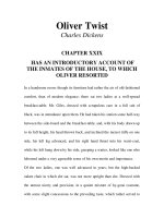
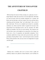
Fig. 29.1. Helical gear
(nomenclature).
herringbone gears) are used. It is equivalent to two single helical gears, in which equal and opposite
thrusts are provided on each gear and the resulting axial thrust is zero.
29.229.2
29.229.2
29.2
TT
TT
T
erer
erer
er
ms used in Helical Gearms used in Helical Gear
ms used in Helical Gearms used in Helical Gear
ms used in Helical Gear
ss
ss
s
The following terms in connection with helical gears, as shown in
Fig. 29.1, are important from the subject point of view.
1. Helix angle. It is a constant angle made by the helices with the
axis of rotation.
2. Axial pitch. It is the distance, parallel to the axis, between similar
faces of adjacent teeth. It is the same as circular pitch and is therefore
denoted by p
c
. The axial pitch may also be defined as the circular pitch
in the plane of rotation or the diametral plane.
3. Normal pitch. It is the distance between similar faces of adjacent
teeth along a helix on the pitch cylinders normal to the teeth. It is denoted
by p
N
. The normal pitch may also be defined as the circular pitch in the normal plane which is a plane
perpendicular to the teeth. Mathematically, normal pitch,
p
N
= p
c
cos !
Note : If the gears are cut by standard hobs, then the pitch (or module) and the pressure angle of the hob will
apply in the normal plane. On the other hand, if the gears are cut by the Fellows gear-shaper method, the pitch
and pressure angle of the cutter will apply to the plane of rotation. The relation between the normal pressure
angle (∀
N
) in the normal plane and the pressure angle (∀) in the diametral plane (or plane of rotation) is given by
tan ∀
N
= tan ∀ × cos !
29.329.3
29.329.3
29.3
FF
FF
F
ace ace
ace ace
ace
WW
WW
W
idth of Helical Gearidth of Helical Gear
idth of Helical Gearidth of Helical Gear
idth of Helical Gear
ss
ss
s
In order to have more than one pair of teeth in contact, the tooth displacement (i.e. the ad-
vancement of one end of tooth over the other end) or overlap should be atleast equal to the axial
pitch, such that
Overlap = p
c
= b tan ! (i)
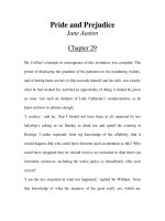
The normal tooth load (W
N
) has two components ; one is tangential component (W
T
) and the
other axial component (W
A
), as shown in Fig. 29.2. The axial or end thrust is given by
W
A
= W
N
sin ! = W
T
tan !
(ii)
From equation (i), we see that as the helix angle increases, then the
tooth overlap increases. But at the same time, the end thrust as given by
equation (ii), also increases, which is undesirable. It is usually recom-
mended that the overlap should be 15 percent of the circular pitch.
# Overlap = b tan ! = 1.15 p
c
or b =
1.15
1.15
tan tan
c
p
m
∃%
&
!!
(
∵
p
c
= %∋m)
where b = Minimum face width, and
m = Module.
Notes : 1. The maximum face width may be taken as 12.5 m to 20 m, where m is
the module. In terms of pinion diameter (D
P
), the face width should be 1.5 D
P
to
2 D
P
, although 2.5 D
P
may be used.
2. In case of double helical or herringbone gears, the minimum face width
is given by
b =
2.3 2.3
tan tan
c
pm
∃%
&
!!
The maximum face width ranges from 20 m to 30 m.
Fig. 29.2. Face width of
helical gear.
1068
n
A Textbook of Machine Design
3. In single helical gears, the helix angle ranges from 20° to 35°, while for double helical gears, it may be
made upto 45°.
29.429.4
29.429.4
29.4
ForFor
ForFor
For
mama
mama
ma
tivtiv
tivtiv
tiv
e or Equive or Equiv
e or Equive or Equiv
e or Equiv
alent Number of alent Number of
alent Number of alent Number of
alent Number of
TT
TT
T
eeth feeth f
eeth feeth f
eeth f
or Helical Gearor Helical Gear
or Helical Gearor Helical Gear
or Helical Gear
ss
ss
s
The formative or equivalent number of teeth for a helical gear may be defined as the number of
teeth that can be generated on the surface of a cylinder having a radius equal to the radius of curvature
at a point at the tip of the minor axis of an ellipse obtained by taking a section of the gear in the normal
plane. Mathematically, formative or equivalent number of teeth on a helical gear,
T
E
= T / cos
3
!
where T = Actual number of teeth on a helical gear, and
! = Helix angle.
29.529.5
29.529.5
29.5
PrPr
PrPr
Pr
oporopor
oporopor
opor
tions ftions f
tions ftions f
tions f
or Helical Gearor Helical Gear
or Helical Gearor Helical Gear
or Helical Gear
ss
ss
s
Though the proportions for helical gears are not standardised, yet the following are recommended
by American Gear Manufacturer's Association (AGMA).
Pressure angle in the plane of rotation,
∀ = 15° to 25°
Helix angle, ! = 20° to 45°
Addendum = 0.8 m (Maximum)
Dedendum = 1 m (Minimum)
Minimum total depth = 1.8 m
Minimum clearance = 0.2 m
Thickness of tooth = 1.5708 m
In helical gears, the teeth are inclined to the axis of the gear.
Hellical Gears
n
1069
29.629.6
29.629.6
29.6
StrStr
StrStr
Str
ength of Helical Gearength of Helical Gear
ength of Helical Gearength of Helical Gear
ength of Helical Gear
ss
ss
s
In helical gears, the contact between mating teeth is gradual, starting at one end and moving
along the teeth so that at any instant the line of contact runs diagonally across the teeth. Therefore in
order to find the strength of helical gears, a modified Lewis equation is used. It is given by
W
T
=((
o
× C
v
) b.%∋m.y'
where W
T
= Tangential tooth load,
(
o
= Allowable static stress,
C
v
= Velocity factor,
b = Face width,
m = Module, and
y' = Tooth form factor or Lewis factor corresponding to the formative
or virtual or equivalent number of teeth.
Notes : 1. The value of velocity factor (C
v
) may be taken as follows :
C
v
=
6
,
6
v)
for peripheral velocities from 5 m / s to 10 m / s.
=
15
,
15
v)
for peripheral velocities from 10 m / s to 20 m / s.
=
0.75
,
0.75 v)
for peripheral velocities greater than 20 m / s.
=
0.75
0.25,
1 v
)
)
for non-metallic gears.
2. The dynamic tooth load on the helical gears is given by
W
D
= W
T
+
2
T
2
T
21 ( . cos ) cos
21 . cos
vbC W
vbC W
!) !
)!)
where v, b and C have usual meanings as discussed in spur gears.
3. The static tooth load or endurance strength of the tooth is given by
W
S
= (
e
.b.%∋m.y'
4. The maximum or limiting wear tooth load for helical gears is given by
W
w
=
P
2
.
cos
DbQK
!
where D
P
, b, Q and K have usual meanings as discussed in spur gears.
In this case, K =
2
N
PG
()sin 1 1
1.4
es
EE
(∀
∗+
)
,−
./
where ∀
N
= Normal pressure angle.
Example 29.1. A pair of helical gears are to transmit 15 kW. The teeth are 20° stub in diametral
plane and have a helix angle of 45°. The pinion runs at 10 000 r.p.m. and has 80 mm pitch diameter.
The gear has 320 mm pitch diameter. If the gears are made of cast steel having allowable static
strength of 100 MPa; determine a suitable module and face width from static strength considerations
and check the gears for wear, given (
es
= 618 MPa.
Solution. Given : P = 15 kW = 15 × 10
3
W; ∀ = 20° ; ! = 45° ; N
P
= 10 000 r.p.m. ; D
P
= 80 mm
= 0.08 m ; D
G
= 320 mm = 0.32 m ; (
OP
= (
OG
= 100 MPa = 100 N/mm
2
; (
es
= 618 MPa = 618 N/mm
2
Module and face width
Let m = Module in mm, and
b = Face width in mm.
1070
n
A Textbook of Machine Design
Since both the pinion and gear are made of the same material (i.e. cast steel), therefore the
pinion is weaker. Thus the design will be based upon the pinion.
We know that the torque transmitted by the pinion,
T =
3
P
60 15 10 60
14.32 N-m
2 2 10 000
P
N
∃∃∃
&&
%%∃
#
*Tangential tooth load on the pinion,
W
T
=
P
14.32
358 N
/ 2 0.08/ 2
T
D
&&
We know that number of teeth on the pinion,
T
P
= D
P
/ m = 80 / m
and formative or equivalent number of teeth for the pinion,
T
E
=
P
33 3
80 / 80/ 226.4
cos cos 45 (0.707)
T
mm
m
&&&
!0
# Tooth form factor for the pinion for 20° stub teeth,
y'
P
=
E
0.841 0.841
0.175 0.175 0.175 0.0037
226.4/
m
Tm
1&1 &1
We know that peripheral velocity,
v =
PP
.
0.08 10000
42 m / s
60 60
DN%
%∃ ∃
&&
# Velocity factor,
C
v
=
0.75 0.75
0.104
0.75 0.75 42
v
&&
))
(
∵
v is greater than 20 m/s)
Since the maximum face width (b) for helical gears may be taken as 12.5 m to 20 m, where m is
the module, therefore let us take
b = 12.5 m
We know that the tangential tooth load (W
T
),
358 = ((
OP
. C
v
) b.%∋m.y'
P
= (100 × 0.104) 12.5 m × %∋m (0.175 – 0.0037 m)
= 409 m
2
(0.175 – 0.0037 m) = 72 m
2
– 1.5 m
3
Solving this expression by hit and trial method, we find that
m = 2.3 say 2.5 mm
Ans.
and face width, b = 12.5 m = 12.5 × 2.5 = 31.25 say 32 mm Ans.
Checking the gears for wear
We know that velocity ratio,
V.R .=
G
P
320
4
80
D
D
&&
# Ratio factor,
Q =
2 24
1.6
1 4 1
VR
VR
∃∃
&&
))
We know that tan ∀
N
= tan ∀ cos ! = tan 20° × cos 45° = 0.2573
#∀
N
= 14.4°
* The tangential tooth load on the pinion may also be obtained by using the relation,
W
T
=
PP
.
, where (in m/ s)
60
PDN
v
v
%
&
Hellical Gears
n
1071
Since both the gears are made of the same material (i.e. cast steel), therefore let us take
E
P
= E
G
= 200 kN/mm
2
= 200 × 10
3
N/mm
2
# Load stress factor,
K =
2
N
PG
()sin
11
1.4
es
EE
(∀
23
)
45
67
=
2
2
33
(618) sin 14.4 1 1
0.678 N/mm
1.4
200 10 200 10
0
23
)&
45
∃∃
67
We know that the maximum or limiting load for wear,
W
w
=
P
22
.
80 32 1.6 0.678
5554 N
cos cos 45
DbQK
∃∃ ∃
&&
!0
Since the maximum load for wear is much more than the tangential load on the tooth, therefore
the design is satisfactory from consideration of wear.
Example 29.2. A helical cast steel gear with 30° helix angle has to transmit 35 kW at 1500
r.p.m. If the gear has 24 teeth, determine the necessary module, pitch diameter and face width for 20°
full depth teeth. The static stress for cast steel may be taken as 56 MPa. The width of face may be
taken as 3 times the normal pitch. What would be the end thrust on the gear? The tooth factor for 20°
full depth involute gear may be taken as
E
.
.,
0 912
0 154
T
1 where T
E
represents the equivalent number
of teeth.
Solution. Given : ! = 30° ; P = 35 kW = 35 × 10
3
W; N = 1500 r.p.m. ; T
G
= 24 ; ∀ = 20° ;
(
o
= 56 MPa = 56 N/mm
2
; b = 3 × Normal pitch = 3 P
N
Module
Let m = Module in mm, and
D
G
= Pitch circle diameter of the gear in mm.
We know that torque transmitted by the gear,
T =
3
3
60 35 10 60
223 N-m 223 10 N-mm
2 2 1500
P
N
∃∃∃
&&&∃
%%∃
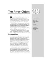
The picture shows double helical gears which are also called herringbone gears.
1072
n
A Textbook of Machine Design
Formative or equivalent number of teeth,
T'
E
=
G
33 3
24 24
37
cos cos 30 (0.866)
T
&&&
!0
# Tooth factor, y' =
E
0.912 0.912
0.154 0.154 0.129
37
T
1&1&
We know that the tangential tooth load,
W
T
=
GG G
22
/2
TTT
DDmT
&&
∃
(
∵
D
G
= m.T
G
)
=
3
2 223 10 18 600
N
24
mm
∃∃
&
∃
and peripheral velocity,
v =
GG
mm/s
60 60
DN mTN
%%
&
(D
G
and m are in mm)
=
24 1500
1885 mm /s 1.885 m/ s
60
m
mm
%∃ ∃ ∃
&&
Let us take velocity factor,
C
v
=
15 15
15 15 1.885vm
&
))
We know that tangential tooth load,
W
T
=((
o
× C
v
) b.% m.y' = ((
o
× C
v
) 3p
N
× %∋m × y' (
∵
b = 3 p
N
)
=((
o
× C
v
) 3 × p
c
cos ! × % m × y' (∵ p
N
= p
c
cos !)
=((
o
× C
v
) 3 % m cos ! × % m × y' (∵ p
c
= % m)
#
18 600
15
56 3 cos 30 0.129
15 1.885
mm
mm
23
&%∃0∃%∃
45
)
67
=
2
2780
15 1.885
m
m
)
or 279 000 + 35 061 m = 2780 m
3
Solving this equation by hit and trial method, we find that
m = 5.5 say 6 mm
Ans.
Pitch diameter of the gear
We know that the pitch diameter of the gear,
D
G
= m × T
G
= 6 × 24 = 144 mm
Ans.
Face width
It is given that the face width,
b =3 p
N
= 3 p
c
cos ! = 3 × %∋m cos !
= 3 × % × 6 cos 30° = 48.98 say 50 mm Ans.
End thrust on the gear
We know that end thrust or axial load on the gear,
W
A
=
18 600 18 600
tan tan 30 0.577
6
T
W
m
!& ∃ 0 & ∃
=1790 N
Ans.
Hellical Gears
n
1073
Example 29.3. Design a pair of helical gears for transmitting 22 kW. The speed of the driver
gear is 1800 r.p.m. and that of driven gear is 600 r.p.m. The helix angle is 30° and profile is
corresponding to 20° full depth system. The driver gear has 24 teeth. Both the gears are made of cast
steel with allowable static stress as 50 MPa. Assume the face width parallel to axis as 4 times the
circular pitch and the overhang for each gear as 150 mm. The allowable shear stress for the shaft
material may be taken as 50 MPa. The form factor may be taken as 0.154 – 0.912 / T
E
, where T
E
is
the equivalent number of teeth. The velocity factor may be taken as
,
350
350 v
)
where v is pitch line
velocity in m / min. The gears are required to be designed only against bending failure of the teeth
under dynamic condition.
Solution. Given : P = 22 kW = 22 × 10
3
W; N
P
= 1800 r.p.m.; N
G
= 600 r.p.m. ; ! = 30° ;
∀ = 20° ; T
P
= 24 ; (
o
= 50 MPa = 50 N/mm
2
; b = 4 p
ct
; Overhang = 150 mm ; 8 = 50 MPa = 50 N/mm
2
Design for the pinion and gear
We know that the torque transmitted by the pinion,
T =
3
P
60 22 10 60
116.7 N-m 116 700 N-mm
2 2 1800
P
N
∃∃∃
&&&
%%∃
Since both the pinion and gear are made of the same material (i.e. cast steel), therefore the
pinion is weaker. Thus the design will be based upon the pinion. We know that formative or equivalent
number of teeth,
T
E
=
P
33 3
24 24
37
cos cos 30 (0.866)
T
&&&
!0
# Form factor, y' =
E
0.912 0.912
0.154 0.154 0.129
37
T
1&1&
Gears inside a car
1074
n
A Textbook of Machine Design
First of all let us find the module of teeth.
Let m = Module in mm, and
D
P
= Pitch circle diameter of the pinion in mm.
We know that the tangential tooth load on the pinion,
W
T
=
PP P
22
/2
TTT
DDmT
&&
∃
(
∵
D
P
= m.T
P
)
=
2 116 700
9725
N
24mm
∃
&
∃
and peripheral velocity, v = % D
P
.N
P
= % m.T
P
.N
P
= % m × 24 × 1800 = 135 735 m mm / min = 135.735 m m / min
# Velocity factor,C
v
=
350 350
350 350 135.735vm
&
))
We also know that the tangential tooth load on the pinion,
W
T
=((
o
.C
v
) b.% m.y' = ((
o
.C
v
) 4 p
c
× %∋m × y' (
∵
b = 4 p
c
)
=((
o
.C
v
) 4 × %∋m × %∋m × y' (
∵
p
c
= %∋m)
#
2
22
9725 350 89 126
50 4 0.129
350 135.735 350 135.735
m
m
mm m
23
&∃%∃&
45
))
67
3.4 × 10
6
+ 1.32 × 10
6
m = 89 126 m
3
Solving this expression by hit and trial method, we find that
m = 4.75 mm say 6 mm
Ans.
We know that face width,
b =4 p
c
= 4 %∋m = 4 % × 6 = 75.4 say 76 mm
Ans.
and pitch circle diameter of the pinion,
D
P
= m × T
P
= 6 × 24 = 144 mm
Ans.
Since the velocity ratio is 1800 / 600 = 3, therefore number of teeth on the gear,
T
G
=3 T
P
= 3 × 24 = 72
and pitch circle diameter of the gear,
D
G
= m × T
G
= 6 × 72 = 432 mm
Ans.
Helical gears.
Hellical Gears
n
1075
Design for the pinion shaft
Let d
P
= Diameter of the pinion shaft.
We know that the tangential load on the pinion,
W
T
=
9725 9725
1621 N
6
m
&&
and the axial load of the pinion,
W
A
= W
T
tan ! = 1621 tan 30°
= 1621 × 0.577 = 935 N
Since the overhang for each gear is 150 mm, therefore bending moment on the pinion shaft due
to the tangential load,
M
1
= W
T
× Overhang = 1621 × 150 = 243 150 N-mm
and bending moment on the pinion shaft due to the axial load,
M
2
=
P
A
144
935 67320 N-mm
22
D
W
∃&∃ &
Since the bending moment due to the tangential load (i.e. M
1
) and bending moment due to the
axial load (i.e. M
2
) are at right angles, therefore resultant bending moment on the pinion shaft,
M =
22 2 2
12
( ) ( ) (243150) (67 320) 252293 N-mm
MM
)& ) &
The pinion shaft is also subjected to a torque T = 116 700 N-mm, therefore equivalent twisting
moment,
T
e
=
22 2 2
(252293) (116700) 277 975 N-mm
MT
)& ) &
We know that equivalent twisting moment (T
e
),
277 975 =
333
PPP
( ) 50 ( ) 9.82 ( )
16 16
ddd
%%
∃8 ∃ &
# (d
P
)
3
= 277 975 / 9.82 = 28 307 or d
P
= 30.5 say 35 mm
Ans.
Let us now check for the principal shear stress.
We know that the shear stress induced,
8 =
2
33
P
16
16 277975
33 N/mm 33 MPa
() (35)
e
T
d
∃
&&&
%%
and direct stress due to axial load,
( =
A2
22
P
935
0.97 N/mm 0.97 MPa
() (35)
44
W
d
&& &
%%
Helical gears
1076
n
A Textbook of Machine Design
# Principal shear stress,
=
22 2 2
11
4 (0.97) 4(33) 33 MPa
22
∗+∗ +
() 8 & ) &
./. /
Since the principal shear stress is less than the permissible shear stress of 50 MPa, therefore the
design is satisfactory.
We know that the diameter of the pinion hub
= 1.8 d
P
= 1.8 × 35 = 63 mm
Ans.
and length of the hub = 1.25 d
P
= 1.25 × 35 = 43.75 say 44 mm
Since the length of the hub should not be less than the face width, therefore let us take length of
the hub as 76 mm.
Ans.
Note : Since the pitch circle diameter of the pinion is 144 mm, therefore the pinion should be provided with a
web. Let us take the thickness of the web as 1.8 m, where m is the module.
# Thickness of the web = 1.8 m = 1.8 × 6 = 10.8 say 12 mm
Ans.
Design for the gear shaft
Let d
G
= Diameter of the gear shaft.
We have already calculated that the tangential load,
W
T
= 1621 N
and the axial load, W
A
= 935 N
# Bending moment due to the tangential load,
M
1
= W
T
× Overhang = 1621 × 150 = 243 150 N-mm
and bending moment due to the axial load,
M
2
=
G
A
432
935 201 960 N-mm
22
D
W
∃&∃&
# Resultant bending moment on the gear shaft,
M =
22 2 2
13
( ) ( ) (243 150) (201 960) 316 000 N-mm
MM
)& ) &
Since the velocity ratio is 3, therefore the gear shaft is subjected to a torque equal to 3 times the
torque on the pinion shaft.
# Torque on the gear shaft,
T = Torque on the pinion shaft × V. R.
= 116 700 × 3 = 350 100 N-mm
We know that equivalent twisting moment,
T
e
=
22 2 2
(316 000) (350 100) 472 000 N-mm
MT
)& ) &
We also know that equivalent twisting moment (T
e
),
472 000 =
333
GGG
( ) 50 ( ) 9.82 ( )
16 16
ddd
%%
∃8∃ & ∃ &
# (d
G
)
3
= 472 000 / 9.82 = 48 065 or d
G
= 36.3 say 40 mm
Ans.
Let us now check for the principal shear stress.
We know that the shear stress induced,
8 =
2
33
G
16
16 472000
37.6 N/mm 37.6 MPa
() (40)
e
T
d
∃
&&&
%%
Hellical Gears
n
1077
and direct stress due to axial load,
( =
A2
22
G
935
0.744 N/mm 0.744 MPa
() (40)
44
W
d
&& &
%%
# Principal shear stress
=
22 2 2
11
4 (0.744) 4 (37.6) 37.6 MPa
22
∗+∗ +
() 8 & ) &
./. /
Since the principal shear stress is less than the permissible shear stress of 50 MPa, therefore the
design is satisfactory.
We know that the diameter of the gear hub
= 1.8 d
G
= 1.8 × 40 = 72 mm
Ans.
and length of the hub = 1.25 d
G
= 1.25 × 40 = 50 mm
We shall take the length of the hub equal to the face width, i.e. 76 mm.
Ans.
Since the pitch circle diameter of the gear is 432 mm, therefore the gear should be provided
with four arms. The arms are designed in the similar way as discussed for spur gears.
Design for the gear arms
Let us assume that the cross-section of the arms is elliptical with major axis (a
1
) equal to twice
the minor axis (b
1
). These dimensions refer to hub end.
# Section modulus of arms,
Z =
23
3
11 1
1
() ()
0.05 ( )
32 64
ba a
a
%%
&&
1
1
2
a
b
23
&
45
67
∵
Since the arms are designed for the stalling load and it is taken as the design tangential load
divided by the velocity factor, therefore
Stalling load, W
S
=
T
350 135.735
1621
350
v
Wm
C
)
23
&
45
67
= 1621
350 135.735 6
5393 N
350
)∃
23
&
45
67
# Maximum bending moment on each arm,
M =
SG
5393 432
291 222 N-mm
242
WD
n
∃& ∃&
We know that bending stress ((
b
),
42 =
3
33
11
291 222 5824 10
0.05 ( ) ( )
M
Z
aa
∃
&&
(Taking (
b
= 42 N/mm
2
)
# (a
1
)
3
= 5824 × 10
3
/ 42 = 138.7 × 10
3
or a
1
= 51.7 say 54 mm
Ans.
and b
1
= a
1
/ 2 = 54 / 2 = 27 mm Ans.
Since the arms are tapered towards the rim and the taper is 1/16 mm per mm length of the arm
(or radius of the gear), therefore
Major axis of the arm at the rim end,
a
2
= a
1
– Taper = a
1
G
1
16 2
D
1∃
=
1 432
54 40 mm
16 2
1∃ &
Ans.
and minor axis of the arm at the rim end,
b
2
= a
2
/ 2 = 40 / 2 = 20 mm Ans.
1078
n
A Textbook of Machine Design
Design for the rim
The thickness of the rim for the pinion may be taken as 1.6 m to 1.9 m, where m is the module.
Let us take thickness of the rim for pinion,
t
RP
= 1.6 m = 1.6 × 6 = 9.6 say 10 mm
Ans.
The thickness of the rim for the gear (t
RG
) is given by
t
RG
= m
G
72
6 25.4 say 26 mm
4
T
n
&&
Ans.
EE
EE
E
XEXE
XEXE
XE
RR
RR
R
CISECISE
CISECISE
CISE
SS
SS
S
1. A helical cast steel gear with 30° helix angle has to transmit 35
kW at 2000 r.p.m. If the gear has 25 teeth, find the necessary
module, pitch diameters and face width for 20° full depth
involute teeth. The static stress for cast steel may be taken as
100 MPa. The face width may be taken as 3 times the normal
pitch. The tooth form factor is given by the expression
y' = 0.154 – 0.912/T
E
, where T
E
represents the equivalent num-
ber of teeth. The velocity factor is given by C
v
=
6
,
6 v)
where
v is the peripheral speed of the gear in m/s.
[Ans. 6 mm ; 150 mm ; 50 mm]
2.
A pair of helical gears with 30° helix angle is used to transmit
15 kW at 10 000 r.p.m. of the pinion. The velocity ratio is 4 : 1.
Both the gears are to be made of hardened steel of static strength 100 N/mm
2
. The gears are 20° stub
and the pinion is to have 24 teeth. The face width may be taken as 14 times the module. Find the
module and face width from the standpoint of strength and check the gears for
wear.
[Ans. 2 mm ; 28 mm]
Gears inside a car engine.
Hellical Gears
n
1079
3. A pair of helical gears consist of a 20 teeth pinion meshing with a 100 teeth gear. The pinion rotates at
720 r.p.m. The normal pressure angle is 20° while the helix angle is 25°. The face width is 40 mm and
the normal module is 4 mm. The pinion as well as gear are made of steel having ultimate strength of
600 MPa and heat treated to a surface hardness of 300 B.H.N. The service factor and factor of safety
are 1.5 and 2 respectively. Assume that the velocity factor accounts for the dynamic load and calculate
the power transmitting capacity of the gears.
[Ans. 8.6 kW]
4.
A single stage helical gear reducer is to receive power from a 1440 r.p.m., 25 kW induction motor. The
gear tooth profile is involute full depth with 20° normal pressure angle. The helix angle is 23°,
number of teeth on pinion is 20 and the gear ratio is 3. Both the gears are made of steel with allowable
beam stress of 90 MPa and hardness 250 B.H.N.
(a) Design the gears for 20% overload carrying capacity from standpoint of bending strength and
wear.
(b) If the incremental dynamic load of 8 kN is estimated in tangential plane, what will be the safe
power transmitted by the pair at the same speed?
Q
UEUE
UEUE
UE
STST
STST
ST
IONSIONS
IONSIONS
IONS
1. What is a herringbone gear? Where they are used?
2. Explain the following terms used in helical gears :
(a) Helix angle; (b) normal pitch; and
(c) axial pitch.
3. Define formative or virtual number of teeth on a helical gear. Derive the expression used to obtain its
value.
4. Write the expressions for static strength, limiting wear load and dynamic load for helical gears and
explain the various terms used therein.
OBJECTOBJECT
OBJECTOBJECT
OBJECT
IVEIVE
IVEIVE
IVE
TT
TT
T
YPYP
YPYP
YP
E E
E E
E
Q
UEUE
UEUE
UE
STST
STST
ST
IONSIONS
IONSIONS
IONS
1. If T is the actual number of teeth on a helical gear and ∀ is the helix angle for the teeth, the formative
number of teeth is written as
(a) T sec
3
∀ (b) T sec
2
∀
(c) T/sec
3
∀ (d) T cosec ∀
2. In helical gears, the distance between similar faces of adjacent teeth along a helix on the pitch cylin-
ders normal to the teeth, is called
(a) normal pitch (b) axial pitch
(c) diametral pitch (d) module
3. In helical gears, the right hand helices on one gear will mesh helices on the other gear.
(a) right hand (b) left hand
4. The helix angle for single helical gears ranges from
(a) 10° to 15° (b) 15° to 20°
(c) 20° to 35° (d) 35° to 50°
5. The helix angle for double helical gears may be made up to
(a) 45° (b) 60°
(c) 75° (d) 90°
ANSWEANSWE
ANSWEANSWE
ANSWE
RR
RR
R
SS
SS
S
1. (a) 2. (a) 3. (b) 4. (c) 5. (a)
GO To FIRST