HIGH-POWER CONVERTERS AND AC DRIVES ppt
Bạn đang xem bản rút gọn của tài liệu. Xem và tải ngay bản đầy đủ của tài liệu tại đây (13.82 MB, 333 trang )
ffirs.qxd
1/3/2007
2:13 PM
Page i
HIGH-POWER CONVERTERS
AND AC DRIVES
ffirs.qxd
1/3/2007
2:13 PM
Page ii
IEEE Press
445 Hoes Lane
Piscataway, NJ 08854
IEEE Press Editorial Board
Mohamed E. El-Hawary, Editor in Chief
M. Akay
J. B. Anderson
R. J. Baker
J. E. Brewer
T. G. Croda
R.J. Herrick
S. V. Kartalopoulos
M. Montrose
M. S. Newman
F. M. B. Pereira
C. Singh
G. Zobrist
Kenneth Moore, Director of IEEE Book and Information Services (BIS)
Catherine Faduska, Acquisitions Editor
Jeannie Audino, Project Editor
ffirs.qxd
1/3/2007
2:13 PM
Page iii
HIGH-POWER CONVERTERS
AND AC DRIVES
Bin Wu
IEEE PRESS
A John Wiley & Sons, Inc., Publication
ffirs.qxd
1/3/2007
2:13 PM
Page iv
Copyright © 2006 by the Institute of Electrical and Electronics Engineers. All rights reserved.
Published by John Wiley & Sons, Inc., Hoboken, New Jersey.
Published simultaneously in Canada.
No part of this publication may be reproduced, stored in a retrieval system, or transmitted in any form
or by any means, electronic, mechanical, photocopying, recording, scanning, or otherwise, except as
permitted under Section 107 or 108 of the 1976 United States Copyright Act, without either the prior
written permission of the Publisher, or authorization through payment of the appropriate per-copy fee to
the Copyright Clearance Center, Inc., 222 Rosewood Drive, Danvers, MA 01923, (978) 750-8400, fax
(978) 750-4470, or on the web at www.copyright.com. Requests to the Publisher for permission should
be addressed to the Permissions Department, John Wiley & Sons, Inc., 111 River Street, Hoboken, NJ
07030, (201) 748-6011, fax (201) 748-6008, or online at />Limit of Liability/Disclaimer of Warranty: While the publisher and author have used their best efforts in
preparing this book, they make no representations or warranties with respect to the accuracy or
completeness of the contents of this book and specifically disclaim any implied warranties of
merchantability or fitness for a particular purpose. No warranty may be created or extended by sales
representatives or written sales materials. The advice and strategies contained herein may not be
suitable for your situation. You should consult with a professional where appropriate. Neither the
publisher nor author shall be liable for any loss of profit or any other commercial damages, including
but not limited to special, incidental, consequential, or other damages.
For general information on our other products and services or for technical support, please contact our
Customer Care Department within the United States at (800) 762-2974, outside the United States at
(317) 572-3993 or fax (317) 572-4002.
Wiley also publishes its books in a variety of electronic formats. Some content that appears in print may
not be available in electronic format. For information about Wiley products, visit our web site at
www.wiley.com.
Library of Congress Cataloging-in-Publication is available.
ISBN-13 978-0-471-73171-9
ISBN-10 0-471-73171-4
Printed in the United States of America.
10 9 8 7 6 5 4 3 2 1
ftoc.qxd
1/3/2007
2:16 PM
Page v
Contents
Preface
xiii
Part One Introduction
1
1. Introduction
1.1
1.2
1.3
1.4
1.5
3
3
Introduction
Technical Requirements and Challenges
5
1.2.1 Line-Side Requirements
5
1.2.2 Motor-Side Challenges
6
1.2.3 Switching Device Constraints
7
1.2.4 Drive System Requirements
8
Converter Configurations
8
MV Industrial Drives
10
Summary
13
References
13
Appendix
14
2. High-Power Semiconductor Devices
2.1
2.2
2.3
2.4
17
Introduction
High-Power Switching Devices
18
2.2.1 Diodes
18
2.2.2 Silicon-Controlled Rectifier (SCR)
18
2.2.3 Gate Turn-Off (GTO) Thyristor
21
2.2.4 Gate-Commutated Thyristor (GCT)
23
2.2.5 Insulated Gate Bipolar Transistor (IGBT)
2.2.6 Other Switching Devices
28
Operation of Series-Connected Devices
28
2.3.1 Main Causes of Voltage Unbalance
29
2.3.2 Voltage Equalization for GCTs
29
2.3.3 Voltage Equalization for IGBTs
31
Summary
32
References
33
17
26
v
ftoc.qxd
1/3/2007
vi
2:16 PM
Page vi
Contents
Part Two Multipulse Diode and SCR Rectifiers
35
3. Multipulse Diode Rectifiers
37
3.1
3.2
3.3
3.4
3.5
Introduction
37
Six-Pulse Diode Rectifier
38
3.2.1 Introduction
38
3.2.2 Capacitive Load
40
3.2.3 Definition of THD and PF
43
3.2.4 Per-Unit System
45
3.2.5 THD and PF of Six-Pulse Diode Rectifier
45
Series-Type Multipulse Diode Rectifiers
47
3.3.1 12-Pulse Series-Type Diode Rectifier
47
3.3.2 18-Pulse Series-Type Diode Rectifier
51
3.3.3 24-Pulse Series-Type Diode Rectifier
54
Separate-Type Multipulse Diode Rectifiers
57
3.4.1 12-Pulse Separate-Type Diode Rectifier
57
3.4.2 18- and 24-Pulse Separate-Type Diode Rectifiers
Summary
61
References
61
4. Multipulse SCR Rectifiers
4.1
4.2
4.3
4.4
4.5
65
Introduction
Six-Pulse SCR Rectifier
65
4.2.1 Idealized Six-Pulse Rectifier
66
4.2.2 Effect of Line Inductance
70
4.2.3 Power Factor and THD
72
12-Pulse SCR Rectifier
74
4.3.1 Idealized 12-Pulse Rectifier
75
4.3.2 Effect of Line and Leakage Inductances
4.3.3 THD and PF
79
18- and 24-Pulse SCR Rectifiers
79
Summary
81
References
81
65
78
5. Phase-Shifting Transformers
5.1
5.2
5.3
5.4
5.5
83
Introduction
Y/Z Phase-Shifting Transformers
83
5.2.1 Y/Z-1 Transformers
83
5.2.2 Y/Z-2 Transformers
85
⌬/Z Transformers
87
Harmonic Current Cancellation
88
5.4.1 Phase Displacement of Harmonic Currents
5.4.2 Harmonic Cancellation
90
Summary
92
61
83
88
ftoc.qxd
1/3/2007
2:16 PM
Page vii
Contents
vii
Part Three Multilevel Voltage Source Converters
93
6. Two-Level Voltage Source Inverter
95
6.1
6.2
6.3
6.4
95
Introduction
Sinusoidal PWM
95
6.2.1 Modulation Scheme
95
6.2.2 Harmonic Content
96
6.2.3 Overmodulation
99
6.2.4 Third Harmonic Injection PWM
99
Space Vector Modulation
101
6.3.1 Switching States
101
6.3.2 Space Vectors
101
6.3.3 Dwell Time Calculation
104
6.3.4 Modulation Index
106
6.3.5 Switching Sequence
107
6.3.6 Spectrum Analysis
108
6.3.7 Even-Order Harmonic Elimination
111
6.3.8 Discontinuous Space Vector Modulation
Summary
116
References
117
115
7. Cascaded H-Bridge Multilevel Inverters
7.1
7.2
7.3
7.4
7.5
7.6
119
Introduction
H-Bridge Inverter
119
7.2.1 Bipolar Pulse-Width Modulation
120
7.2.2 Unipolar Pulse-Width Modulation
121
Multilevel Inverter Topologies
123
7.3.1 CHB Inverter with Equal dc Voltage
123
7.3.2 H-Bridges with Unequal dc Voltages
126
Carrier Based PWM Schemes
127
7.4.1 Phase-Shifted Multicarrier Modulation
127
7.4.2 Level-Shifted Multicarrier Modulation
131
7.4.3 Comparison Between Phase- and Level-Shifted
PWM Schemes
136
Staircase Modulation
139
Summary
141
References
142
8. Diode-Clamped Multilevel Inverters
8.1
8.2
119
143
Introduction
Three-Level Inverter
143
8.2.1 Converter Configuration
8.2.2 Switching State
144
143
143
ftoc.qxd
1/3/2007
viii
2:16 PM
Page viii
Contents
8.3
8.4
8.5
8.6
8.7
8.2.3 Commutation
145
Space Vector Modulation
148
8.3.1 Stationary Space Vectors
149
8.3.2 Dwell Time Calculation
149
Ǟ
8.3.3 Relationship Between Vref Location and Dwell Times
154
8.3.4 Switching Sequence Design
154
8.3.5 Inverter Output Waveforms and Harmonic Content
160
8.3.6 Even-Order Harmonic Elimination
160
Neutral-Point Voltage Control
164
8.4.1 Causes of Neutral-Point Voltage Deviation
165
8.4.2 Effect of Motoring and Regenerative Operation
165
8.4.3 Feedback Control of Neutral-Point Voltage
166
Other Space Vector Modulation Algorithms
167
8.5.1 Discontinuous Space Vector Modulation
167
8.5.2 SVM Based on Two-Level Algorithm
168
High-Level Diode-Clamped Inverters
168
8.6.1 Four- and Five-Level Diode-Clamped Inverters
169
8.6.2 Carrier-Based PWM
170
Summary
173
References
175
Appendix
176
9. Other Multilevel Voltage Source Inverters
9.1
9.2
9.3
9.4
179
179
Introduction
NPC/H-Bridge Inverter
179
9.2.1 Inverter Topology
179
9.2.2 Modulation Scheme
180
9.2.3 Waveforms and Harmonic Content
181
Multilevel Flying-Capacitor Inverters
183
9.3.1 Inverter Configuration
183
9.3.2 Modulation Schemes
184
Summary
186
References
186
Part Four PWM Current Source Converters
187
10. PWM Current Source Inverters
189
10.1 Introduction
10.2 PWM Current Source Inverter
190
10.2.1 Trapezoidal Modulation
191
10.2.2 Selective Harmonic Elimination
189
194
ftoc.qxd
1/3/2007
2:16 PM
Page ix
Contents
ix
10.3 Space Vector Modulation
200
10.3.1 Switching States
200
10.3.2 Space Vectors
201
10.3.3 Dwell Time Calculation
203
10.3.4 Switching Sequence
205
10.3.5 Harmonic Content
208
10.3.6 SVM Versus TPWM and SHE
209
10.4 Parallel Current Source Inverters
209
10.4.1 Inverter Topology
209
10.4.2 Space Vector Modulation for Parallel Inverters
210
10.4.3 Effect of Medium Vectors on dc Currents
212
10.4.4 dc Current Balance Control
213
10.4.5 Experimental Verification
214
10.5 Load-Commutated Inverter (LCI)
215
10.6 Summary
216
References
217
Appendix
218
11. PWM Current Source Rectifiers
219
11.1 Introduction
11.2 Single-Bridge Current Source Rectifier
219
11.2.1 Introduction
219
11.2.2 Selective Harmonic Elimination
220
11.2.3 Rectifier dc Output Voltage
225
11.2.4 Space Vector Modulation
227
11.3 Dual-Bridge Current Source Rectifier
227
11.3.1 Introduction
227
11.3.2 PWM Schemes
228
11.3.3 Harmonic Contents
229
11.4 Power Factor Control
231
11.4.1 Introduction
231
11.4.2 Simultaneous ␣ and ma Control
232
11.4.3 Power Factor Profile
235
11.5 Active Damping Control
236
11.5.1 Introduction
236
11.5.2 Series and Parallel Resonant Modes
237
11.5.3 Principle of Active Damping
238
11.5.4 LC Resonance Suppression
240
11.5.5 Harmonic Reduction
242
11.5.6 Selection of Active Damping Resistance
245
11.6 Summary
246
References
247
Appendix
248
219
ftoc.qxd
1/3/2007
x
2:16 PM
Page x
Contents
Part Five High-Power AC Drives
12. Voltage Source Inverter-Fed Drives
251
253
253
12.1 Introduction
12.2 Two-Level VBSI-Based MV Drives
253
12.2.1 Power Converter Building Block
253
12.2.2 Two-Level VSI with Passive Front End
254
12.3 Neutral-Point Clamped (NPC) Inverter-Fed Drives
257
12.3.1 GCT-Based NPC Inverter Drives
257
12.3.2 IGBT-Based NPC Inverter Drives
260
12.4 Multilevel Cascaded H-Bridge (CHB) Inverter-Fed Drives
261
12.4.1 CHB Inverter-Fed Drives for 2300-V/4160-V Motors
261
12.4.2 CHB Inverter Drives for 6.6-kV/11.8-kV Motors
264
12.5 NPC/H-Bridge Inverter-Fed Drives
264
12.6 Summary
265
References
265
13. Current Source Inverter-Fed Drives
269
269
13.1 Introduction
13.2 CSI Drives with PWM Rectifiers
269
13.2.1 CSI Drives with Single-bridge PWM Rectifier
269
13.2.2 CSI Drives for Custom Motors
273
13.2.3 CSI Drives with Dual-Bridge PWM Rectifier
275
13.3 Transformerless CSI Drive for Standard AC Motors
276
13.3.1 CSI Drive Configuration
276
13.3.2 Integrated dc Choke for Common-Mode Voltage
Suppression
277
13.4 CSI Drive with Multipulse SCR Rectifier
279
13.4.1 CSI Drive with 18-Pulse SCR Rectifier
279
13.4.2 Low-Cost CSI Drive with 6-Pulse SCR Rectifier
280
13.5 LCI Drives for Synchronous Motors
281
13.5.1 LCI Drives with 12-Pulse Input and 6-Pulse Output
281
13.5.2 LCI Drives with 12-Pulse Input and 12-Pulse Output
282
13.6 Summary
282
References
283
14. Advanced Drive Control Schemes
285
14.1 Introduction
14.2 Reference Frame Transformation
285
14.2.1 abc/dq Frame Transformation
286
14.2.2 3/2 Stationary Transformation
288
14.3 Induction Motor Dynamic Models
288
14.3.1 Space Vector Motor Model
288
285
ftoc.qxd
1/3/2007
2:16 PM
Page xi
Contents
14.4
14.5
14.6
14.7
14.8
14.9
xi
14.3.2 dq-Axis Motor Model
290
14.3.3 Induction Motor Transient Characteristics
291
Principle of Field-Oriented Control (FOC)
296
14.4.1 Field Orientation
296
14.4.2 General Block Diagram of FOC
297
Direct Field-Oriented Control
298
14.5.1 System Block Diagram
298
14.5.2 Rotor Flux Calculator
299
14.5.3 Direct FOC with Current-Controlled VSI
301
Indirect Field-Oriented Control
305
FOC for CSI-Fed Drives
307
Direct Torque Control
309
14.8.1 Principle of Direct Torque Control
310
14.8.2 Switching Logic
311
14.8.3 Stator Flux and Torque Calculation
313
14.8.4 DTC Drive Simulation
314
14.8.5 Comparison Between DTC and FOC Schemes
316
Summary
316
References
317
Abbreviations
319
Appendix Projects for Graduate-Level Courses
321
P. 1 Introduction
321
P. 2 Sample Project
322
P. 3 Answers to Sample Project
324
Index
329
About the Author
333
fpref.qxd
1/3/2007
2:17 PM
Page xiii
Preface
With technology advancements in semiconductor devices such as insulated gate
bipolar transistors (IGBTs) and gate commutated thyristors (GCTs), modern highpower medium voltage (MV) drives are increasingly used in petrochemical, mining, steel and metals, transportation and other industries to conserve electric energy,
increase productivity and improve product quality.
Although research and development of the medium voltage (2.3 KV to 13.8 KV)
drive in the 1-MW to 100-MW range are continuously growing, books dedicated to
this technology seem unavailable. This book provides a comprehensive analysis on
a variety of high-power converter topologies, drive system configurations, and advanced control schemes.
This book presents the latest technology in the field, provides design guidance
with tables, charts and graphs, addresses practical problems and their mitigation
methods, and illustrates important concepts with computer simulations and experiments. It serves as a reference for academic researchers, practicing engineers, and
other professionals. This book also provides adequate technical background for
most of its topics such that it can be adopted as a textbook for a graduate-level
course in power electronics and ac drives.
This book is presented in five parts with fourteen chapters. Part One, Introduction, provides an overview of high-power MV drives, which includes market analysis, drive system configurations, typical industrial applications, power converter
topologies and semiconductor devices. The technical requirements and challenges
for the MV drive are highlighted; these are different in many aspects from those for
low-voltage drives.
Part Two, Multipulse Diode and SCR Rectifiers, covers 12-, 18- and 24-pulses
rectifier topologies commonly used in the MV drive for the reduction of line current
distortion. The configuration of phase-shifting (zigzag) transformers and principle
of harmonic cancellation are discussed.
Part Three, Multilevel Voltage Source Inverters, presents detailed analysis on
various multilevel voltage source inverter (VSI) topologies, including neutral point
clamped and cascaded H-bridge inverters. Carrier-based and space-vector modulation schemes for the multilevel inverters are elaborated.
Part Four, PWM Current Source Converters, deals with a number of current
source inverters (CSI) and rectifiers for the MV drive. Several modulation techniques such as trapezoidal pulse width modulations, selective harmonics eliminaxiii
.
fpref.qxd
1/3/2007
xiv
2:17 PM
Page xiv
Preface
tion and space vector modulations are analyzed. Unity-power factor control and active damping control for the current source rectifiers are also included.
Part Five, High-Power ac Drives, focuses on various configurations of VSI- and
CSI-fed MV drives marketed by major drive manufacturers. The features and limitations of these drives are discussed. Two advanced drive control schemes, field
oriented control and direct torque control, are analyzed. Efforts are made to present
these complex schemes in a simple, easy to understand manner.
The Appendix at the end of the book provides a list of 12 simulation based projects for use in a graduate course. The detailed instruction for the projects and their
answers are included in Instructor’s Manual (published separately). Since the book
is rich in illustrations, Power Point slides for each of the chapters are included in the
manual.
Finally, I would like to express my deep gratitude to my colleagues at Rockwell
Automation Canada; in particular, Steve Rizzo, Navid Zargari, and Frank DeWinter, for numerous discussions and 12 years of working together in developing advanced MV-drive technologies. I sincerely thank my supervisors, Drs. Shashi
Dowan and Gordon Slemon for their valuable advice on high-power drive research
during my graduate studies at the University of Toronto. I am also indebted to Dr.
Robert Hanna at RPM Engineering Ltd. for his review of the manuscript and constructive comments. I am grateful to my postdoctoral fellows and graduate students
in the Laboratory for Electric Drive Applications and Research (LEDAR) at Ryerson University for their assistance in preparing the manuscript of this book. I am
thankful to my colleagues at ASI Robicon, ABB, Siemens AG, and Rockwell Automation for providing the photos of the MV drives. I also wish to acknowledge the
support and inspiration of my wife, Janice, and my daughter, Linda, during the
preparation of this book.
BIN WU
Toronto, Canada
December 2005
c01.qxd
12/29/2005
3:44 PM
Page 1
Part One
Introduction
c01.qxd
12/29/2005
3:44 PM
Chapter
Page 3
1
Introduction
1.1
INTRODUCTION
The development of high-power converters and medium-voltage (MV) drives started in the mid-1980s when 4500-V gate turn off (GTO) thyristors became commercially available [1]. The GTO was the standard for the MV drive until the advent of
high-power insulated gate bipolar transistors (IGBTs) and gate commutated thyristors (GCTs) in the late 1990s [2, 3]. These switching devices have rapidly progressed into the main areas of high-power electronics due to their superior switching characteristics, reduced power losses, ease of gate control, and snubberless
operation.
The MV drives cover power ratings from 0.4 MW to 40 MW at the mediumvoltage level of 2.3 kV to 13.8 kV. The power rating can be extended to 100 MW,
where synchronous motor drives with load commutated inverters are often used [4].
However, the majority of the installed MV drives are in the 1- to 4-MW range with
voltage ratings from 3.3 kV to 6.6 kV as illustrated in Fig. 1.1-1.
The high-power MV drives have found widespread applications in industry.
They are used for pipeline pumps in the petrochemical industry [5], fans in the cement industry [6], pumps in water pumping stations [7], traction applications in the
transportation industry [8], steel rolling mills in the metals industry [9], and other
applications [10,11]. A summary of the MV drive applications is given in the appendix of this chapter [12].
Since the beginning of the 21st century a few thousands of MV drives have been
commissioned worldwide. Market research has shown that around 85% of the total
installed drives are for pumps, fans, compressors and conveyors [13], where the
drive system may not require high dynamic performance. As shown in Fig. 1.1-2,
only 15% of the installed drives are nonstandard drives.
One of the major markets for the MV drive is for retrofit applications. It is reported that 97% of the currently installed MV motors operate at a fixed speed and
only 3% of them are controlled by variable-speed drives [13]. When fans or pumps
are driven by a fixed-speed motor, the control of air or liquid flow is normally
achieved by conventional mechanical methods, such as throttling control, inlet
dampers, and flow control valves, resulting in a substantial amount of energy loss.
High-Power Converters and ac Drives. By Bin Wu
© 2006 The Institute of Electrical and Electronics Engineers, Inc.
3
c01.qxd
12/29/2005
4
3:44 PM
Chapter 1
Page 4
Introduction
Power
Range
0.4 MW
1 MW
2 MW
4 MW
10 MW
40 MW
2.3 kV
3.3 kV
4.16 kV
6.6 kV
11 kV
13.8 kV
Voltage
Range
Figure 1.1-1
Voltage and power ranges of the MV drive. Source: Rockwell Automation.
The installation of the MV drive can lead to a significant savings on energy cost. It
was reported that the use of the variable-speed MV drive resulted in a payback time
of the investment from one to two and a half years [7].
The use of the MV drive can also increase productivity in some applications. A
case was reported from a cement plant where the speed of a large fan was made adjustable by an MV drive [11]. The collected dust on the fan blades operated at a
fixed speed had to be cleaned regularly, leading to a significant downtime per year
for maintenance. With variable-speed operation, the blades only had to be cleaned
at the standstill of the production once a year. The increase in productivity together
with the energy savings resulted in a payback time of the investment within six
months.
Figure 1.1-3 shows a general block diagram of the MV drive. Depending on the
system requirements and the type of the converters employed, the line- and motorside filters are optional. A phase shifting transformer with multiple secondary windings is often used mainly for the reduction of line current distortion.
The rectifier converts the utility supply voltage to a dc voltage with a fixed or adjustable magnitude. The commonly used rectifier topologies include multipulse
Pumps
40%
Fans
30%
Compressors,
extruders, conveyors
15%
Fixed-speed MV motors
97%
Nonstandard or
engineered drives
15%
(a) Load types for the MV drive
Figure 1.1-2
Variable-speed MV drives
3%
(b) MV drives versus MV motors
MV drive market survey. Source: ABB.
c01.qxd
12/29/2005
3:44 PM
Page 5
1.2
Technical Requirements and Challenges
Ld
L
~
C
Cd
L
~
Optional
Supply
C
M
Optional
Line-side
Transformer Rectifier
filter
Figure 1.1-3
5
dc Filter
Motor-side Motor
Inverter
filter
General block diagram of the MV drive.
diode rectifiers, multipulse SCR rectifiers, or pulse-width-modulated (PWM) rectifiers. The dc filter can simply be a capacitor that provides a stiff dc voltage in voltage source drives or an inductor that smoothes the dc current in current source drives.
The inverter can be generally classified into voltage source inverter (VSI) and
current source inverter (CSI). The VSI converts the dc voltage to a three-phase ac
voltage with adjustable magnitude and frequency whereas the CSI converts the dc
current to an adjustable three-phase ac current. A variety of inverter topologies
have been developed for the MV drive, most of which will be analyzed in this
book.
1.2
TECHNICAL REQUIREMENTS AND CHALLENGES
The technical requirements and challenges for the MV drive differ in many aspects
from those for the low-voltage (Յ 600 V) ac drives. Some of them that must be addressed in the MV drive may not even be an issue for the low-voltage drives. These
requirements and challenges can be generally divided into four groups: the requirements related to the power quality of line-side converters, the challenges associated
with the design of motor-side converters, the constraints of the switching devices,
and the drive system requirements.
1.2.1
Line-Side Requirements
(a) Line Current Distortion. The rectifier normally draws distorted line current from the utility supply, and it also causes notches in voltage waveforms. The
distorted current and voltage waveforms can cause numerous problems such as nuisance tripping of computer-controlled industrial processes, overheating of transformers, equipment failure, computer data loss, and malfunction of communications equipment. Nuisance tripping of industrial assembly lines often leads to
expensive downtime and ruined product. There exist certain guidelines for harmonic regulation, such as IEEE Standard 519-1992 [14]. The rectifier used in the MV
drive should comply with these guidelines.
c01.qxd
12/29/2005
6
3:44 PM
Chapter 1
Page 6
Introduction
(b) Input Power Factor. High input power factor is a general requirement for
all electric equipment. Most of the electric utility companies require their customers
to have a power factor of 0.9 or above to avoid penalties. This requirement is especially important for the MV drive due to its high power rating.
(c) LC Resonance Suppression. For the MV drives using line-side capacitors for current THD reduction or power factor compensation, the capacitors form
LC resonant circuits with the line inductance of the system. The LC resonant modes
may be excited by the harmonic voltages in the utility supply or harmonic currents
produced by the rectifier. Since the utility supply at the medium voltage level normally has very low line resistance, the lightly damped LC resonances may cause severe oscillations or overvoltages that may destroy the switching devices and other
components in the rectifier circuits. The LC resonance issue should be addressed
when the drive system is designed.
1.2.2
Motor-Side Challenges
(a) dv/dt and Wave Reflections. Fast switching speed of the semiconductor devices results in high dv/dt at the rising and falling edges of the inverter
output voltage waveform. Depending on the magnitude of the inverter dc bus voltage and speed of the switching device, the dv/dt can well exceed 10,000 V/s.
The high dv/dt in the inverter output voltage can cause premature failure of the
motor winding insulation due to partial discharges. It induces rotor shaft voltages
through stray capacitances between the stator and rotor. The shaft voltage produces a current flowing into the shaft bearing, leading to early bearing failure. The
high dv/dt also causes electromagnetic emission in the cables connecting the motor to the inverter, affecting the operation of nearby sensitive electronic equipment.
To make the matter worse, the high dv/dt may cause a voltage doubling effect at
the rising and falling edges of the motor voltage waveform due to wave reflections
in long cables. The reflections are caused by the mismatch between the wave impedance of the cable and the impedances at its inverter and motor ends, and they
can double the voltage on the motor terminals at each switching transient if the cable length exceeds a certain limit. The critical cable length for 500 V/s is in the
100-m range, for 1000 V/s in the 50-m range, and for 10,000 V/s in the 5-m
range [15].
(b) Common-Mode Voltage Stress. The switching action of the rectifier
and inverter normally generates common-mode voltages [16]. The common-mode
voltages are essentially zero-sequence voltages superimposed with switching noise.
If not mitigated, they will appear on the neutral of the stator winding with respect to
ground, which should be zero when the motor is powered by a three-phase balanced
utility supply. Furthermore, the motor line-to-ground voltage, which should be
equal to the motor line-to-neutral (phase) voltage, can be substantially increased
c01.qxd
12/29/2005
3:44 PM
Page 7
1.2
Technical Requirements and Challenges
7
due to the common-mode voltages, leading to the premature failure of the motor
winding insulation system. As a consequence, the motor life expectancy is shortened.
It is worth noting that the common-mode voltages are generated by the rectification and inversion process of the converters. This phenomenon is different from the
high dv/dt caused by the switching transients of the high speed switches. It should
be further noted that the common-mode voltage issue is often ignored in the lowvoltage drives. This is partially due to the conservative design of the insulation system for low-voltage motors. In the MV drives, the motor should not be subject to
any common-mode voltages. Otherwise, the replacement of the damaged motor
would be very costly in addition to the loss of production.
(c) Motor Derating. High-power inverters may generate a large amount of
current and voltage harmonics. These harmonics cause additional power losses in
the motor winding and magnetic core. As a consequence, the motor is derated and
cannot operate at its full capacity.
(d) LC Resonances. For the MV drives with a motor-side filter capacitor, the
capacitor forms an LC resonant circuit with the motor inductances. The resonant
mode of the LC circuit may be excited by the harmonic voltages or currents produced by the inverter. Although the motor winding resistances may provide some
damping, this problem should be addressed at the design stage of the drive.
(e) Torsional Vibration. Torsional vibrations may occur in the MV drive due
to the large inertias of the motor and its mechanical load. The drive system may
vary from a simple two-inertia system consisting of only the motor and the load inertias to very complex systems such as a steel rolling-mill drive with more than 20
inertias. The torsional vibrations may be excited when the natural frequency of the
mechanical system is coincident with the frequency of torque pulsations caused by
distorted motor currents. Excessive torsional vibrations can result in broken shafts
and couplings, and also cause damages to the other mechanical components in the
system.
1.2.3
Switching Device Constraints
(a) Device Switching Frequency. The device switching loss accounts for
a significant amount of the total power loss in the MV drive. The switching loss
minimization can lead to a reduction in the operating cost when the drive is commissioned. The physical size and manufacturing cost of the drive can also be reduced due to the reduced cooling requirements for the switching devices. The other
reason for limiting the switching frequency is related to the device thermal resistance that may prevent efficient heat transfer from the device to its heatsink. In
practice, the device switching frequency is normally around 200 Hz for GTOs and
500 Hz for IGBTs and GCTs.
c01.qxd
12/29/2005
8
3:44 PM
Chapter 1
Page 8
Introduction
The reduction of switching frequency generally causes an increase in harmonic
distortion of the line- and motor-side waveforms of the drive. Efforts should be
made to minimize the waveform distortion with limited switching frequencies.
(b) Series Connection. Switching devices in the MV drive are often connected in series for medium-voltage operation. Since the series connected devices and
their gate drivers may do not have identical static and dynamic characteristics, they
may not equally share the total voltage in the blocking mode or during switching
transients. A reliable voltage equalization scheme should be implemented to protect
the switching devices and enhance the system reliability.
1.2.4
Drive System Requirements
The general requirements for the MV drive system include high efficiency, low
manufacturing cost, small physical size, high reliability, effective fault protection,
easy installation, self-commissioning, and minimum downtime for repairs. Some of
the application-specific requirements include high dynamic performance, regenerative braking capability, and four-quadrant operation.
1.3
CONVERTER CONFIGURATIONS
Multipulse rectifiers are often employed in the MV drive to meet the line-side harmonic requirements. Figure 1.3-1 illustrates a block diagram of 12-, 18- and 24pulse rectifiers. Each multipulse rectifier is essentially composed of a phase-shifting transformer with multiple secondary windings feeding a set of identical
six-pulse rectifiers.
Utility
grid
Six-pulse
rectifier
Phase-shifting
transformer
Six-pulse
rectifier
(a) 12-Pulse rectifier
(b) 18-Pulse rectifier
Figure 1.3-1
(c) 24-Pulse rectifier
Multipulse diode/SCR rectifiers.
c01.qxd
12/29/2005
3:44 PM
Page 9
1.3
Converter Configurations
9
~
Cd
Cd
~
Cd
~
Cd
~
Cd
~
Two-level
inverter
Neutral-point
clamped inverter
Figure 1.3-2
Cascaded
H-bridge inverter
Flying capacitor
inverter
Per-phase diagram of VSI topologies.
Both diode and SCR devices can be used as switching devices. The multipulse
diode rectifiers are suitable for VSI-fed drives while the SCR rectifiers are normally for CSI drives. Depending on the inverter configuration, the outputs of the sixpulse rectifiers can be either connected in series to form a single dc supply or connected directly to a multilevel inverter that requires isolated dc supplies. In addition
to the diode and SCR rectifiers, PWM rectifiers using IGBT or GCT devices can
also be employed, where the rectifier usually has the same topology as the inverter.
To meet the motor-side challenges, a variety of inverter topologies can be adopted for the MV drive. Figure 1.3-2 illustrates per-phase diagram of commonly used
Ld
Ld
Ld
SM
Load-commutated
inverter
Figure 1.3-3
~
PWM SCI
~
Cf
~
Cf
Parallel PWM CSI
Per-phase diagram of CSI topologies.
c01.qxd
12/29/2005
10
3:44 PM
Chapter 1
Page 10
Introduction
three-phase multilevel VSI topologies, which include a conventional two-level inverter, a three-level neutral-point clamped (NPC) inverter, a seven-level cascaded
H-bridge inverter and a four-level flying-capacitor inverter. Either IGBT or GCT
can be employed in these inverters as a switching device.
Current source inverter technology has been widely accepted in the drive industry. Figure 1.3-3 shows the per-phase diagram of the CSI topologies for the MV
drive. The SCR-based load-commutated inverter (LCI) is specially suitable for very
large synchronous motor drives, while the PWM current source inverter is a preferred choice for most industrial applications. The parallel PWM CSI is composed
of two or more single-bridge inverters connected in parallel for super-high-power
applications. Symmetrical GCTs are normally used in the PWM current source inverters.
1.4
MV INDUSTRIAL DRIVES
A number of MV drive products are available on the market today. These drives
come with different designs using various power converter topologies and control
schemes. Each design offers some unique features but also has some limitations.
The diversified offering promotes the advancement in the drive technology and the
market competition as well. A few examples of the MV industrial drives are as follows.
Figure 1.4-1 illustrates the picture of an MV drive rated at 4.16 kV and 1.2 MW.
The drive is composed of a 12-pulse diode rectifier as a front end and a three-level
Figure 1.4-1
(ACS1000).
GCT-based three-level NPC inverter-fed MV drive. Courtesy of ABB
c01.qxd
12/29/2005
3:45 PM
Page 11
1.4
MV Industrial Drives
11
Figure 1.4-2 IGBT-based three-level NPC inverter-fed MV drive. Courtesy of Siemens
(SIMOVERT MV).
NPC inverter using GCT devices. The drive’s digital controller is installed in the
left cabinet. The cabinet in the center houses the diode rectifier and air-cooling system of the drive. The inverter and its output filters are mounted in the right cabinet.
The phase-shifting transformer for the rectifier is normally installed outside the
drive cabinets.
Figure 1.4-2 shows an MV drive using an IGBT-based three-level NPC inverter.
The IGBT–heatsink assemblies in the central cabinet are constructed in a modular
fashion for easy assembly and replacement. The front end converter is a standard
12-pulse diode rectifier for line current harmonic reduction. The phase-shifting
transformer for the rectifier is not included in the drive cabinet.
A 4.16-kV 7.5-MW cascaded H-bridge inverter-fed drive is illustrated in Fig.
1.4-3. The inverter is composed of 15 identical IGBT power cells, each of which
can be slid out for quick repair or replacement. The waveform of the inverter lineto-line voltage is composed of 21 levels, leading to near-sinusoidal waveforms
without using LC filters. The drive employs a 30-pulse diode rectifier powered by a
phase-shifting transformer with 15 secondary windings. The transformer is installed
in the left cabinets to reduce the installation cost of the cables connecting its secondary windings to the power cells.
Figure 1.4-4 shows a current source inverter-fed MV drive with a power range
from 2.3 MW to 7 MW. The drive comprises two identical PWM GCT current
c01.qxd
12/29/2005
12
3:45 PM
Chapter 1
Page 12
Introduction
Figure 1.4-3 IGBT cascaded H-bridge inverter-fed MV drive. Courtesy of ASI Robicon
(Perfect Harmony).
Figure 1.4-4 CSI-fed MV drive using symmetrical GCTs. Courtesy of Rockwell
Automation (PowerFlex 7000).
c01.qxd
12/29/2005
3:45 PM
Page 13
References
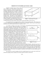
Table 1.4-1
13
Summary of the MV Drive Products Marketed by Major Drive Manufacturers
Multilevel cascaded
H-bridge inverter
Power Range
(MVA)
IGBT
1.4–7.2
Alstom (VDM5000)
GCT
0.3–5
3–27
3–20
IGBT
IGBT
Two-level voltage
source inverter
Three-level neutral point
clamped inverter
Switching
Device
GCT
Inverter Configuration
0.6–7.2
0.3–2.4
IGBT
0.3–22
ABB (ACS1000)
(ACS6000)
General Electric
(Innovation Series MV-SP)
Siemens (SIMOVERT-MV)
General Electric-Toshiba
(Dura-Bilt5 MV)
ASI Robicon (Perfect
Harmony)
Toshiba (TOSVERT-MV)
General Electric (Innovation
MV-GP Type H)
Toshiba (TOSVERT
300 MV)
Alstom (VDM6000
Symphony)
Rockwell Automation
(PowerFlex 7000)
Siemens (SIMOVERT S)
ABB (LCI)
Alstom (ALSPA SD7000)
0.5–6
0.45–7.5
NPC/H-bridge inverter
IGBT
0.4–4.8
Flying-capacitor inverter
IGBT
0.3–8
PWM current source
inverter
Load commutated inverter
Symmetrical
GCT
SCR
0.2–20
>10
>10
>10
Manufacturer
source converters, one for the rectifier and the other for the inverter. The converters
are installed in the second cabinet from the left. The dc inductor required by the current source drive is mounted in the fourth cabinet. The fifth (right most) cabinet
contains drive’s liquid cooling system. With the use of a special integrated dc inductor having both differential- and common-mode inductances, the drive does not
require an isolation transformer for the common-mode voltage mitigation, leading
to a reduction in manufacturing cost.
Table 1.4-1 provides a summary of the MV drive products offered by major
drive manufacturers in the world, where the inverter configuration, switching device, and power range of the drive are listed.
1.5
SUMMARY
This chapter provides an overview of high-power converters and medium-voltage
(MV) drives, including market analysis, drive system configurations, power converter topologies, drive product analysis, and major manufacturers. The technical
requirements and challenges for the MV drive are also summarized. These require-