Tài liệu Microwave Waveguides and Coaxial Cable pptx
Bạn đang xem bản rút gọn của tài liệu. Xem và tải ngay bản đầy đủ của tài liệu tại đây (102.61 KB, 5 trang )
b
a
TE
TE
TE
10
20
30
E Field
Relative Magnitude
Waveguide Cross Section
6-1.1
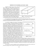
Figure 1. The Rectangular Waveguide
Figure 2. TE modes
MICROWAVE WAVEGUIDES and COAXIAL CABLE
In general, a waveguide consists of a hollow metallic
tube of arbitrary cross section uniform in extent in the
direction of propagation. Common waveguide shapes are
rectangular, circular, and ridged. The rectangular waveguide
has a width a and height b as shown in figure 1. Commonly
used rectangular waveguides have an aspect ratio b/a of
approximately 0.5. Such an aspect ratio is used to preclude
generation of field variations with height and their attendant
unwanted modes. Waveguides are used principally at
frequencies in the microwave range; inconveniently large
guides would be required to transmit radio-frequency power
at longer wavelengths. In the X-Band frequency range of 8.2
to 12.4 GHz, for example, the U.S. standard rectangular
waveguide, WR-90, has an inner width of 2.286 cm (0.9 in.) and an inner height of 1.016 cm (0.4 in.).
In waveguides the electric and magnetic fields are confined to the space within the guides. Thus no power is lost
to radiation. Since the guides are normally filled with air, dielectric losses are negligible. However, there is some I R power
2
lost to heat in the walls of the guides, but this loss is usually very small.
It is possible to propagate several modes of electromagnetic
waves within a waveguide. The physical dimensions of a waveguide
determine the cutoff frequency for each mode. If the frequency of the
impressed signal is above the cutoff frequency for a given mode, the
electromagnetic energy can be transmitted through the guide for that
particular mode with minimal attenuation. Otherwise the electromagnetic
energy with a frequency below cutoff for that particular mode will be
attenuated to a negligible value in a relatively short distance. This
grammatical use of cutoff frequency is opposite that used for coaxial
cable, where cutoff frequency is for the highest useable frequency. The
dominant mode in a particular waveguide is the mode having the lowest
cutoff frequency. For rectangular waveguide this is the TE mode. The
10
TE (transverse electric) signifies that all electric fields are transverse to
the direction of propagation and that no longitudinal electric field is
present. There is a longitudinal component of magnetic field and for this
reason the TE waves are also called H waves. The TE designation is
mn mn
usually preferred. Figure 2 shows a graphical depiction of the E field
variation in a waveguide for the TE TE , and TE modes. As can be
10, 20 30
seen, the first index indicates the number of half wave loops across the
width of the guide and the second index, the number of loops across the height of the guide - which in this case is zero. It
is advisable to choose the dimensions of a guide in such a way that, for a given input signal, only the energy of the dominant
mode can be transmitted through the guide. For example, if for a particular frequency, the width of a rectangular guide is
too large, then the TE mode can propagate causing a myriad of problems. For rectangular guides of low aspect ratio the
20
TE mode is the next higher order mode and is harmonically related to the cutoff frequency of the TE mode. It is this
20 10
relationship together with attenuation and propagation considerations that determine the normal operating range of
rectangular waveguide.
The discussion on circular waveguides will not be included because they are rarely used in the EW area.
Information regarding circular waveguides can be found in numerous textbooks on microwaves.
A
E
F
C
B
D
6-1.2
Figure 3. Double Ridge Waveguide
(Table 2 Lists Dimensions A, B, C, D, E, & F)
CHARACTERISTICS OF STANDARD RECTANGULAR WAVEGUIDES
Rectangular waveguides are commonly used for power transmission at microwave frequencies. Their physical
dimensions are regulated by the frequency of the signal being transmitted. Table 1 tabulates the characteristics of the
standard rectangular waveguides. It may be noted that the number following the EIA prefix "WR" is in inside dimension
of the widest part of the waveguide, i.e. WR90 has an inner dimension of 0.90".
DOUBLE RIDGE RECTANGULAR WAVEGUIDE
Another type of waveguide commonly used in EW systems
is the double ridge rectangular waveguide. The ridges in this
waveguide increase the bandwidth of the guide at the expense of
higher attenuation and lower power-handling capability. The
bandwidth can easily exceed that of two contiguous standard
waveguides. Introduction of the ridges mainly lowers the cutoff
frequency of the TE mode from that of the unloaded guide, which
10
is predicated on width alone. The reason for this can easily be
explained when the field configuration in the guide at cutoff is
investigated. At cutoff there is no longitudinal propagation down the
guide. The waves simply travel back and forth between the side walls
of the guide. In fact the guide can be viewed as a composite parallel plate waveguide of infinite width where the width corre-
sponds to the direction of propagation of the normal guide. The TE mode cutoff occurs where this composite guide has
10
its lowest-order resonant frequency. This occurs when there is only one E field maximum across the guide which occurs
at the center for a symmetrical ridge. Because of the reduced height of the guide under the ridge, the effective TE mode
10
resonator is heavily loaded as though a shunt capacitor were placed across it. The cutoff frequency is thus lowered
considerably. For the TE mode the fields in the center of the guide will be at a minimum. Therefore the loading will have
20
a negligible effect. For guides of proper aspect ratio, ridge height, and ridge width, an exact analysis shows that the TE
10
mode cutoff can be lowered substantially at the same time the TE and TE mode cutoffs are raised slightly. Figure 3
20 30
shows a typical double ridged waveguide shape and Table 2 shows double ridged waveguide specifications. In the case of
ridged waveguides, in the EIA designation, (WRD350 D36) the first "D" stands for double ridged ("S" for single ridged),
the 350 is the starting frequency (3.5 GHz), and the "D36" indicates a bandwidth of 3.6:1. The physical dimensions and
characteristics of a WRD350 D24 and WRD350 D36 are radically different. A waveguide with a MIL-W-23351 dash
number beginning in 2 (i.e. 2-025) is a double ridge 3.6:1 bandwidth waveguide. Likewise a 1- is a single ridge 3.6:1, a
3- is a single ridge 2.4:1, and a 4- is a double ridge 2.4:1 waveguide.
Figure 4 shows a comparison of the frequency /attenuation characteristics of various waveguides. The attenuation
is based on real waveguides which is higher than the theoretical values listed in Tables 1 and 2. Figure 5 shows attenuation
characteristics of various RF coaxial cables.
6-1.3
Figure 4. Attenuation vs Frequency for a Variety of Waveguides and Cables
6-1.4
Table 1. Rectangular Waveguide Specifications
Waveguide JAN WG MIL-W-85 Material (at 1 Atm)
Size Desig Dash #
Freq
Range Cutoff (dB/100ft)
(GHz) (GHz)
Freq
Power Dimensions (Inches)
Insertion Loss
Outside Wall
Thickness
CW Peak
WR284 RG48/U 1-039 Copper 2.60 - 2.08 45 7650 .742-.508 3.000x1.500 0.08
RG75/U 1-042 Aluminum 3.95 36 1.116-.764
WR229 RG340/U 1-045 Copper 3.30 - 2.577 30 5480 .946-.671 2.418x1.273 0.064
RG341/U 1-048 Aluminum 4.90 24 1.422-1.009
WR187 RG49/U 1-051 Copper 3.95 - 3.156 18 3300 1.395-.967 1.000x1.000 0.064
RG95/U 1-054 Aluminum 5.85 14.5 2.097-1.454
WR159 RG343/U 1-057 Copper 4.90 - 3.705 15 2790 1.533-1.160 1.718x0.923 0.064
RG344/U 1-060 Aluminum 7.05 12 2.334-1.744
WR137 RG50/U 1-063 Copper 5.85 - 4.285 10 1980 1.987-1.562 1.500x0.750 0.064
RG106/U 1-066 Aluminum 8.20 8 2.955-2.348
WR112 RG51/U 1-069 Copper 7.05 - 5.26 6 1280 2.776-2.154 1.250x0.625 0.064
RG68/U 1-072 Aluminum 10.0 4.8 4.173-3.238
WR90 RG52/U 1-075 Copper 8.2 - 6.56 3 760 4.238-2.995 1.000x0.500 0.05
RG67/U 1-078 Aluminum 12.4 2.4 6.506-4.502
WR75 RG346/U 1-081 Copper 10.0 - 7.847 2.8 620 5.121-3.577 0.850x0.475 0.05
RG347/U 1-084 Aluminum 15.0 2.2 7.698-5.377
WR62 RG91/U 1-087 Copper 12.4 - 9.49 1.8 460 6.451-4.743 0.702x0.391 0.04
RG349/U 1-091 Aluminum 18.0 1.4 9.700-7.131
WR51 RG352/U 1-094 Copper 15.0 - 11.54 1.2 310 8.812-6.384 0.590x0.335 0.04
RG351/U 1-098 Aluminum 22.0 1 13.250-9.598
WR42 RG53/U 1-100 Copper 18.0 - 14.08 0.8 170 13.80-10.13 0.500x0.250 0.04
26.5
WR34 RG354/U 1-107 Copper 2.0 - 17.28 0.6 140 16.86-11.73 0.420x0.250 0.04
33.0
WR28 RG271/U 3-007 Copper 26.5 - 21.1 0.5 100 23.02-15.77 0.360x0.220 0.04
40.0
6-1.5
Figure 5. Attenuation vs Frequency for a Variety of Coaxial Cables
Table 2. Double Ridge Rectangular Waveguide Specifications
Waveguide 23351 Material Range Cutoff (at 1 Atm) Loss (dB/ft)
Size Dash # (GHz) (GHz)
MIL-W- Freq Freq Power Insertion Dimensions (Inches)
CW Peak A B C D E F
WRD250 Alum 2.60 - 2.093 24 120 0.025 1.655 0.715 2 1 0.44 0.15
Brass 7.80 0.025
Copper 0.018
Silver Al 0.019
WRD350 4-029 Alum 3.50 - 2.915 18 150 0.0307 1.48 0.688 1.608 0.816 0.37 0.292
D24 4-303 Brass 8.20 0.0303
4-031 Copper 0.0204
WRD475 4-033 Alum 4.75 - 3.961 8 85 0.0487 1.09 0.506 1.19 0.606 0.272 0.215
D24 4-034 Brass 11.00 0.0481
4-035 Copper 0.0324
WRD500 2-025 Alum 5.00 - 4.222 4 15 0.146 0.752 0.323 0.852 0.423 0.188 0.063
D36 2-026 Brass 18.00 0.141
2-027 Copper 0.095
WRD650 Alum 6.50 - 5.348 4 25 0.106 0.721 0.321 0.821 0.421 0.173 0.136
Brass 18.00 0.105
Copper 0.07
WRD750 4-037 Alum 7.50 - 6.239 4.8 35 0.0964 0.691 0.321 0.791 0.421 0.173 0.136
D24 4-038 Brass 18.00 0.0951
4-039 Copper 0.0641
WRD110 4-041 Alum 11.00 - 9.363 1.4 15 0.171 0.471 0.219 0.551 0.299 0.118 0.093
D24 4-042 Brass 26.50 0.169
4-043 Copper 0.144
WRD180 4-045 Alum 18.00 - 14.995 0.8 5 0.358 0.288 0.134 0.368 0.214 0.072 0.057
D24 4-046 Brass 40.00 0.353
4-047 Copper 0.238