- Trang chủ >>
- Khoa Học Tự Nhiên >>
- Vật lý
Iron catalytic growth of prism shaped single crystal silicon nanowires by chemical vapor deposition of silane
Bạn đang xem bản rút gọn của tài liệu. Xem và tải ngay bản đầy đủ của tài liệu tại đây (566.71 KB, 5 trang )
Iron-catalytic growth of prism-shaped single-crystal silicon
nanowires by chemical vapor deposition of silane
Chen Li
a,b,1
, Chi Gu
a,b,1
, Zengtao Liu
a,b
, Jinxiao Mi
c
, Yong Yang
a,b,
*
a
State Key Laboratory for Physical Chemistry of Solid Surfaces, Xiamen University, Xiamen, Fujian 361005, China
b
Department of Chemistry, Xiamen University, Xiamen, Fujian 361005, China
c
Department of Material Science and Engineering, Xiamen University, Xiamen, Fujian 361005, China
Received 26 April 2005; in final form 9 May 2005
Available online 29 June 2005
Abstract
Single-crystal silicon nanowires with the prism structures were synthesized by chemical vapor deposition of SiH
4
gas at 450 °C.
Fe particles which were located at the tip of the CNTs were employed as a catalyst for the growth of silicon nanowires (SiNWs).
Transmission electron microscopy studies of the materials showed that the nanowires have a diameter of 50–70 nm and a length of
several micrometers. High-resolution transmission electron microscopy demonstrated that the nanowires have excellent single-crys-
tal characteristics. Both the CNTs and Fe play a key role in the growth process of the SiNWs. A growth mechanism was proposed
for the growth of silicon nanowires under our experimental conditions.
Ó 2005 Elsevier B.V. All rights reserved.
1. Introduction
One-dimensional nanostructures are significant for
nanoscale devices based on their distinctive struc tures
and properties. Since silicon has long been the dominant
material in semiconductor and microelectronics indus-
tries, thus the study of synthesis and properties of
nanostructured silicon material is one of the most
important subjects in the research of nanostructured
material field. Nanostructured silicon such as wires [1],
ribbons [2] and tubes [3] have been widely studied for
the applications in nanoscale electronics and photonics
[4], field-effect transistors (FETs) [5] and so on. Many
efforts have been made to prepare silicon nanowires
(SiNWs) by different methods, such as laser ablation
[6,7], thermal evaporation deposition [8], chemical vapor
deposition (CVD) [9–11], and supercritical fluid–liquid–
solid (SFLS) synthesis [12]. The most popular growth
mechanism for SiNWs is vapor–liquid–solid (VLS)
growth mechanism [13,14]. In VLS process, a metal,
such as gold or iron that forms a low temperature eutec-
tic phase with silicon is used as the catalyst that has been
heated to a temperature greater than the eutectic tem-
perature (363 °C for Au–Si, 1207 °C for Fe–Si) [15].In
addition, oxide-assisted-growth (OAG) method [16]
has also been developed to produce large quantities of
SiNWs. There, an excimer laser is used to ablat e a solid
composite target of highly Si powder mixed metals (Fe,
Ni or Co). The target temperature was 1100–1400 °C
and the nanowires growth temperature was selected as
900–1100 °C. In general, when using pure Fe metal as
a catalyst for the growth of silicon nanowires, almost
all methods in the literatures [6,16] require the growth
temperature higher than 1000 °C. It is quite difficult to
grow single-crystal SiNWs without Au catalyst assis-
tance at the lower temperature.
In this work, the SiNWs were grown at 450 °Cby
using common catalyst of iron (Fe), which was
previously used as a catalyst for growing CNTs. More
0009-2614/$ - see front matter Ó 2005 Elsevier B.V. All rights reserved.
doi:10.1016/j.cplett.2005.05.117
*
Corresponding author. Fax: +86 592 2185753.
E-mail addresses: (Y. Yang), chenli@xmu.
edu.cn (C. Li).
1
These authors contributed equally to this work.
www.elsevier.com/locate/cplett
Chemical Physics Letters 411 (2005) 198–202
importantly, it should be noted that the growth of the
SiNWs here is different from the conventional VLS
mechanism, revealing the crystalline structures of the
crystal may have influence on the structure of the grown
one-dimensional nanostructures. The interface between
Si and Fe prefers to take the least lattice mismatch.
2. Experimental
The anodic aluminum oxide (AAO) templates were
formed by using a two-step anodization method as re-
ported in our previous paper [17]. Then, a small
amount of iron was deposited into the bottom of
the AAO pores using an alternating current (AC) elec-
trodeposition method. Electrodeposition was carried
out in a ammonium iron (II) sulfate hexahydrate
(NH
4
)
2
Fe(SO
4
)
2
Æ 6H
2
O solution (30 g/L, pH 5.0) at
50 Hz. After that, the CNTs were formed in the pores
of AAO template by pyrolyzing a flow of mixture of
acetylene (10 sccm) and nitrogen (50 sccm) at 650 °C
for 1 h. In order to expose CNTs tips containing iron
catalyst, we remove the AAO template partly before
deposition of silicon. Prior to the pyrolysis of silane,
the quartz boat tube furnace was purged with pure
nitrogen gas, while it was cooled down to 450 °C.
While the flow of pure nitrogen gas (50 sccm) remains
as a carrier gas, a flow of 5% silane (diluted in high
purity argon) with a flow rate of 5 sccm (Si partial
pressure of 4 Torr) was pyrolyzed to grow silicon
nanostructure under Fe catalysis at the tip of the
CNTs. Several sets of pyrolysis times were imple-
mented in our experiments to form the SiNWs with
different lengths. The sample was investigated in scan-
ning electron microscopy (SEM) (Oxford Company,
LEO-1530). Furthermore, AA O templates together
with product were dissolved in a 50% H
3
PO
4
for
1 h, then in a 1 M NaOH to remove the residue alu-
minum and AAO template completely. The samples
were prepared for high-resolution transmission micros-
copy (HRTEM) (FEI Company, TECNAI-F30) obser-
vation and energy dispersive X-ray (EDX) spectra
examination.
3. Results and discussion
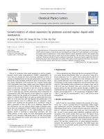
Fig. 1 is an SEM image for the cross-sectional view of
the SiNWs on CNTs array after partly dissolving the
AAO template. It can be seen that one-dimensional sil-
icon nanowires were exactly located at the end of the
carbon nanotubes with high density. These SiNWs
tended to ÔstickÕ to each other. The diameter of the
SiNWs is about 50–70 nm, which is well consistent with
the diameter of the CNTs and AAO pores. It also can be
seen that most SiNWs have a length of several microns.
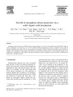
Figs. 2a,b are the TEM images and HRTEM image
which provide an insight into the structure of the
SiNWs, respectively. These SiNWs were broken down
from the CNTs during ultrasonica lly cleaning for
TEM observation. It can be found from Fig. 2a that
the as-grown SiNWs are actually the prism-shaped
nanostructures. Fig. 2b displ ays a typical HRTEM im-
age taken from the edge area of the SiNWs (indicated
by the box area in Fig. 2a). Detailed analysis on lattice
images give interplanar spacing of 0.31 nm, closely cor-
responding to that of Si(1 1 1) plane which reveals the
growth direction [1 1 1] of these SiNWs. A selected-area
electron diffraction (SAED) pattern (see Fig. 2a, left in-
set) taken from top face (Fig. 2a, indicated by red arrow)
of the tilted image was taken along [1 1 1] zone axis of
single crystal Si. Another SAED pattern was taken
along [2 1 1] zone axis of single crystal Si (see Fig. 2b,
left inset). From the data above, we can confirm the
as-grown prism of single crystal SiNWs (Fig. 1a) is a
combination assembled by (1 1 1) and (À1 À1 À1),
(2 À1 À1) and (À2 1 1), (0 1 À1) and (0 À1 1) three pairs
of parallel planes. It belongs to cubic silicon structure
with a = 0.5341 nm, space group Fd3m. Fig. 2c gives
an EDX spectra taken from an individual SiNW, which
further confirmed that the nanowires are compose of
silicon with a minimal content of oxygen.
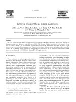
In order to further investigate the growth process of
the SiNWs, different pyrolysis time of silane were carried
out in this work. It can be found from Figs. 3a–d that
there are different morphologies of the SiNWs at differ-
ent growth stages. With the increasing of pyrolysis time
of silane, a triangle-shaped silicon tip at initial stage
Fig. 1. The SEM image of the SiNWs grown on the CNTs after
removing the AAO template partly.
C. Li et al. / Chemical Physics Letters 411 (2005) 198–202 199
transforms gradually to a square, ultimately to SiNWs.
It also can be revealed that in growth process of SiNWs,
the CNTs have a size-confined effect on the grow th of
SiNWs through confining the size of metal catalyst. In
our approach, no SiNWs were formed at 450 °C just
with Fe catalysis. This implied that the CNTs play an
important role on growth of the SiNWs. It has been re-
ported that carbothermal reduction of the CNTs can
help silicon powder to form nanostructures [18,19].
Thus, it is believed that the CNTs facilitate the pyrolysis
of silane and growth of the SiNWs. That is, the CNTs,
as an assistance of the Fe catalyst, help to greatly de-
crease the reaction temperature. During the whole
CVD process, the CNTs always keep Fe particles active
state and maintain highly reductive atmosphere arou nd
them when silane diffuses into them.
It can be clearly seen from Fig. 4 that Fe particle is
located between C and Si and joints them for each
other (see Fig. 4b), which is different from the conven-
tional vapor–liquid–solid (VLS) growth mechanism re-
ported before [9]. In addition, the temperature of
growing silicon is just 450 °C which is far below the
eutectic temperature of Fe–Si alloy (>1200 °C). The
450 °C just reach the temperature where SiH
4
start a
decomposing reaction. The normal VLS mechanism
is not applicable to explain our results. Fig. 4a shows
Fig. 2. (a) The TEM image of the SiNWs with a SAED image (upper left inset) taken from the face indicated by the red arrow and a schematic
representation of crystal faces grown (lower left inset). (b) The HRTEM images of the enlarged box area in (a) with its SAED image (left inset).
(c) EDX spectrum taken from an individual SiNWs. (For interpretation of the references to the color in this figure legend, the reader is referred to the
web version of this article.)
200 C. Li et al. / Chemical Physics Letters 411 (2005) 198–202
a HRTEM image of triangle-shaped area of the
CNTs–Fe–Si junction which provides the information
of the starting nucleation. The recipro cal lattice peaks,
which were obtained from fast fourier transforms
(FFT) of the lattice-resolved images of outer layer
area (Fig. 4a, left inset) shows the interplanar spacing
values of about 0.38, 0.22 and 0.31 nm which are in-
dexed to the (1 1 0), (2 1 1) and (1 1 1) silicon planes,
respectively. Fourier transforms image of an inner cat-
alyst area (Fig. 4, right inset) solely exhibits Fe(1 1 0)
of an identified spacing value of 0.20 nm. It should be
noted that the spacing values of Si(2 2 0) (d
220
=
1.9201 A
˚
) and Si(2 1 1) (d
211
= 2.2172 A
˚
), which help
to form the prism shaped SiNWs, are very close to
one of Fe(1 1 0) plane (d
110
= 2.0268 A
˚
).
It has been reported that the crystallographic lattice
structure at the interface is important in defining the
structural characteristics of the grown nanowires. The
interface prefers to take the least lattice mismatch [20].
Thus, we think the preferred growth direction and the
3D-prism shape should be determined by the Fe(1 1 0)
as is discussed above. It is confirmed by an elemental
mapping (Fig. 4b) of another developing junction
specimen at early stage. The Si(2 2 0) and Si(2 1 1) which
are the side planes of the prism shaped SiNWs, are
determined by the Fe(1 1 0) as these planes are well
matched to Fe(1 1 0). Thus, the specific plane of Fe
particles play an important role in initiating nucleation
and growth of silicon nanostructures, resulting in mor-
phology and orientation control. The interface between
Si and Fe prefers to take the least lattice mismatch.
Besides, the Si{1 1 1} has the lowest surface energy
among the Si simple index surfaces. In a word, with
the assistance of the CNTs and the catalysis of Fe par-
ticles, preference of taking the least lattice mismatch be-
tween Si and Fe leads to the growth of the single-crystal
SiNWs with well-defined structures at the lower
temperature.
4. Summary
In conclusion, by chemical vapor deposition of silane,
the large-scale SiNWs were grown under the catalysis of
Fe particles at the lower temperature – 450 °C. These
nanowires have a diameter of 50–70 nm and a length
Fig. 3. TEM images of silicon nanostructures growth by different pyrolysis time of silane. (a) a triangle-shaped silicon tip grown on a CNT by 30-min
pyrolysis time. (b) A rectangle silicon grown on a CNT by 40-min pyrolysis time and white arrow indicates transformation direction from triangle-
shaped silicon to rectangle silicon. (c) 150 min. (d) 240 min.
C. Li et al. / Chemical Physics Letters 411 (2005) 198–202 201
of several microns. Through the HRTEM and SAED
observation, the nanowires exhibit the excellent single
crystal nature. At the whole growth process, the CNTs
not only have a size-confined effect on the growth of
SiNWs, but also facilitate the pyrolysis and deposition
of silane on iron and growth of the SiNWs because of
their carbothermal reduction. The growth process pro-
posed here which is different from the conventional
VLS process should be ascribe to preference of taking
the least lattice mismatch between Si and Fe. The pref-
erence leads to the control of morphology and crystal-
line orientation of the SiNWs.
Acknowledgments
We are grateful for financial support from National
Natural Science Foundation of China (Grant Nos.
29925310 and 20021002) and Ministry of Science and
Technology of China (Grant No. 2001CB10506).
References
[1] A.M. Morales, C.M. Lieber, Science 279 (1998) 208.
[2] W. Shi, H. Peng, N. Wang, C.P. Li, L. Xu, C.S. Lee, R. Kalish,
S.T. Lee, J. Am. Chem. Soc. 123 (2001) 11095.
[3] J. Sha, J. Niu, X. Ma, J. Xu, X. Zhang, Q. Yang, D. Yang, Adv.
Mater. 14 (2002) 1219.
[4] C.M. Lieber, Sci. Am. 285 (2001) 58.
[5] Y. Cui, Q. Wei, H. Park, C.M. Lieber, Science 293 (2001)
1289.
[6] Y.F. Zhang, Y.H. Tang, H.Y. Peng, N. Wang, C.S. Lee, I. Bello,
S.T. Lee, Appl. Phys. Lett. 75 (1999) 1842.
[7] X. Duan, C.M. Lieber, J. Am. Chem. Soc. 122 (2000) 188.
[8] S.T. Lee, N. Wang, C.S. Lee, Mater. Sci. Eng. A 286 (2000) 16.
[9] Y. Cui, L.J. Lauhon, M.S. Gudiksen, J. Wang, C.M. Lieber,
Appl. Phys. Lett. 78 (2001) 2214.
[10] X.Y. Zhang, L.D. Zhang, G.W. Meng, G.H. Li, N.Y. Phillipp,
F. Phillipp, Adv. Mater. 13 (2001) 1238.
[11] J.T. Hu, O.Y. Min, P. Yang, C.M. Lieber, Nature 399 (1999) 48.
[12] T. Hanrath, B.A. Korgel, Adv. Mater. 15 (2003) 437.
[13] R.S. Wagner, W.C. Ellis, Appl. Phys. Lett. 4 (1964) 89.
[14] C.M. Lieber, Solid State Commun. 107 (1998) 106.
[15] J. Hu, T.W. Odom, C.M. Lieber, Accounts Chem. Res. 32 (1999)
435.
[16] R.Q. Zhang, Y. Lifshitz, S.T. Lee, Adv. Mater. 7–8 (2003) 635.
[17] J. Zhao, Q.Y. Gao, C. Gu, Y. Yang, Chem. Phys. Lett. 358
(2002) 77.
[18] G. Gundiah, F.L. Deepak, A. Govindaraj, C.N.R. Rao, Chem.
Phys. Lett. 381 (2003) 579.
[19] P. Scheier, B. Marson, M. Lonfat, W. Schneider, K. Sattler, Surf.
Sci. 458 (2000) 113.
[20] Y. Ding, P.X. Gao, Z.L. Wang, J. Am. Chem. Soc. 126 (2004)
2066.
Fig. 4. (a) TEM image of a triangle shaped silicon, the upper-left inset
is the two-dimensional fourier transform of the outer layer of the
triangle (indicated by arrow) depicting lattice spacing of Si(1 1 1) of
0.31 nm, Si(2 1 1) of 0.22 nm and Si(2 2 0) of 0.38 nm, respectively, the
bottom-right inset is the two-dimensional fourier transform of central
part of the triangle image (also indicated by arrow) depicting lattice
spacing of 0.207 nm, which is indexed to Fe(1 1 0). (b) TEM image and
its element-mapping of triangle-shaped region. The insets are the
distribution of C, Fe and Si, respectively.
202 C. Li et al. / Chemical Physics Letters 411 (2005) 198–202