Báo cáo " Growth of CdS thin films by chemical bath deposition technique " pptx
Bạn đang xem bản rút gọn của tài liệu. Xem và tải ngay bản đầy đủ của tài liệu tại đây (563.58 KB, 5 trang )
VNU Journal of Science, Mathematics - Physics 24 (2008) 119-123
119
Growth of CdS thin films by chemical bath
deposition technique
Be Xuan Hop*, Ha Van Trinh, Khuc Quang Dat, Phung Quoc Bao
Department of Physics, College of Sciences, VNU, 334 Nguyen Trai, Thanh Xuan, Hanoi, Vietnam
Received 29 April 2008; received in revised form 04 September 2008
Abstract. The structural, morphological and optical properties of CBD deposited CdS thin films
have been studied by varying the processing parameters and the Cd/S ratio of the starting
precursors in order to better understand the growth conditions. The films were characterized by X-
ray diffraction, SEM, Raman, and photoluminescence spectroscopy. XRD patterns show that as-
deposited CdS films were polycrystalline. The grain size are increasing with increasing the Cd/S
ratio and/or the deposition time. The fact that the symmetry-dependent Raman bands of the CdS
thin films under investigation did not appear indicates the poor preferential orientation of as-
deposited CdS crystallites, which is in accordance with the measured XRD pattern.
Keywords: CdS thin film; chemical bath deposition.
1. Introduction
Chalcogenide semiconductor thin films are being intensively investigated for low-cost
photovoltaic and optoelectronic applications [1,2]. Cadmium sulfide is commonly used as n-type
semiconducting layer for heterojunction thin films solar cells. Multilayered CdS films can be
employed in the manufacture of the optoelectronic devices.
The deposition of CdS film has been explored by various techniques, such as thermal
evaporation [3], sputtering [4], molecular beam epitaxy [5], spray pyrolysis [6], chemical bath
deposition [7]. Chemical bath deposition is a method of growing thin films of certain materials on a
substrate immersed in an aqueous bath containing appropriate reagents at temperatures ranging from
room temperature to 100°C. It has been identified as a low process suitable for the preparation of large
area thin films [8]. In this study, we report the preparation of CdS thin films onto microscope glass
slides by CBD method. The structural, morphological and optical properties of the as-prepared films
are investigated under various processing conditions.
2. Experimental detail
2.1. Synthesis
Reagents used for the deposition include cadmium sulfate CdSO
4
, ammonia water NH
4
OH and
thiourea CS(NH
2
)
2
. All reagents are of analytical grade and used without further purification. The
______
*
Corresponding author. Tel.: 0983712941
E-mail:
B.X. Hop et al. / VNU Journal of Science, Mathematics - Physics 24 (2008) 119-123
120
glass substrates were soaked in 5% HF solution, left then for 20 minutes under ultrasonic duty in
isopropyl alcohol, washed with distilled water and finally dried in the air.
The typical procedure for the film growth is described as follows. Drop by and by 25 % NH
4
OH
into a 100 ml beaker containing 25 ml of 1M CdSO
4
solution until the initially formed white
precipitate is completely dissolved. The clean substrates are mounted vertically in the bath beaker in
such a way that an approximately 5 mm thick layer of deposition bath separates the substrates each
other and the wall of the bath. 25 ml of 1M CS(NH
2
)
2
then is poured into the mixtures. Finally, the
distilled water is gradually added to make the volume up to 100 ml. The deposition is made at 60°C
under magnetic stirring for all samples. To vary the composition of the films, different concentrates of
the CdSO
4
and thiourea are used.
The CdS formation is detailed in the following series of chemical reactions:
4 4 2 4 2 4
CdSO NH OH Cd(OH) (NH ) SO
+ ↔ +
2
2 4 3 4 2
Cd(OH) 4NH OH Cd(NH ) 2OH 4H O
+ −
+ ↔ + +
|
2 2 2
SHS
H N C H N H N C NH
− − ↔ − =
| |
2 2 2
S OH
H N C H N OH H N C NH SH
− −
− = + ↔ − = +
2
3 4 4 3
Cd(NH ) SH CdS NH 3NH
+ − +
+ = ↓ + +
CdS thin films formed on the substrates are optically transparent, adherent, homogeneous and
yellowish in colour without any powdered precipitation.
After deposition, the substrate were removed from the chemical bath, cleaned thoroughly in
distilled water and dried in the air at room temperature. The deposition time is chosen to be 2 h for the
bath containing 25 ml of 1M CdSO
4
solution and 9 h for the bath with 3 ml of 1M CdSO
4
solution.
2.2. Characterization
The X-ray diffraction (XRD) patterns of the as-deposited CdS thin film were recorded in a
D5005 Brucker X-ray diffractometer with CuK
α
radiation
λ
= 1.54056°A, operated at 40 kV and 40
mA. The scanning speed was 0.030 °/s in the 2
θ
range from 5° to 65°. The scanning electron
microscopy (SEM) images of the obtained CdS thin films were taken on a JEOL5410. The Raman
spectroscopy measurements were made a LABRAM-1B (Jobin Yvon Spex) using 180 grooves/mm
diffraction grating, D 0.3 filter and a He-Ne laser of the wavelength 632,817 nm as a light source. The
photoluminescence spectra at room temperature of the investigated samples were measured on a FPL-
322 spectrofluorometer (Jobin Yvon Spex) using a Xenon400 lamp as the excitation light source.
3. Results and discussion
3.1. X-ray Diffraction (XRD) Analysis
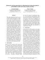
The typical diffractogram of the as-deposited CdS thin films is shown in Fig. 1. XRD analysis
indicated that the film are polycrystalline with less pronounced orientation along a c-axis ((002)
direction) perpendicular to the substrate plan. The degree of the preferential orientation may be
increasing with the post-deposition annealing temperature. Although the (002) orientation is not very
B.X. Hop et al. / VNU Journal of Science, Mathematics - Physics 24 (2008) 119-123
121
pronounced, in comparison with [9] (inset in Fig. 1), the obtained CdS thin film have only the cubic
structure (zincblende type). One can see the observed diffraction peaks at the 2
θ
values of 26.5, 30.8,
43.9, and 52.1° correspond to reflections from (111), (200), (220), and (311) planes of cubic CdS [10].
Table 1. Standard ASTM card for CdS [10]
2
θ
d(A
0
) hkl
24.828 3.580 100
26.449 3.360 002
α
- CdS
28.216 3.159 101
36.648 - 102
43.735 2.067 110
α
- CdS
51.875 1.761
112
β
- CdS
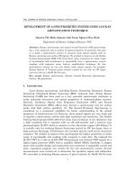
3.2. Scanning Electron Microscopy (SEM) Imaging
To study the homogeneity of the films and to compare one with another, the surface
investigations in the SEM imaging were performed. The most homogeneous film (Fig. 2a) were
obtained in the bath with 3 ml of 1M CdSO
4
solution for 9 h. In this case, the slow deposition rate led
to the small uniform grain size and shape and the good adhesion to the substrate. On the films
deposited in the bath containing 25 ml of 1M CdSO
4
solution for 2 h (Fig. 2b), one can see many
scattered particles about 2 microns in diameter and their conglomerates up to 4
µ
m. The
heterogeneity increase with increasing the Cd/S ration in the bath due to the violent precipitation.
Fig. 1. Typical X-ray diffractogram of CdS thin films as grown. Inset shows XRD
pattern of the CdS thin films reported in [9].
B.X. Hop et al. / VNU Journal of Science, Mathematics - Physics 24 (2008) 119-123
122
(a) (b)
Fig. 2. SEM images of CdS thin films prepared in the bath with 3 ml of 1M CdSO
4
solution for 9h (a) and with
25 ml of 1M CdSO
4
solution for 2h (b).
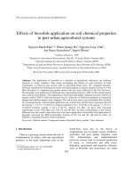
3.3. Raman spectroscopy
The typical Raman spectrum of the as-prepared CdS thin films is displayed in Fig. 3. The
related researches [6] show that Raman spectra of CdS thin films strongly depends on the film grain
size and thickness. One can see only a relatively large band centered at ca. 300 cm
-1
. This peak can be
identified as the first overtone of the longitudinal optical phonons (1LO) by comparing with CdS
Raman spectra obtained in [10]. The fact that the characteristic Raman bands at 500cm
-1
and 1100cm
-1
corresponding to the symmetry-dependent normal oscillations did not appear indicates the poor
preferential orientation of as-deposited CdS crystallite, which is in accordance with the XRD pattern
shown in Fig. 1.
Fig. 3. Typical Raman spectrum of the as-prepared CdS thin films.
3.4. Photoluminescence spectra
Preliminary investigations show that photoluminescence (PL) spectra of the obtained CdS thin
films have two distinct bands at ca. 465 nm and ca. 549 nm, respectively. The measured PL excitation
spectra corresponding to the two emission bands allows to fix the excitation wavelength at ca. 369 nm
suitable to the CdS thin films under consideration. The typical PL spectrum is presented in Fig. 4.
B.X. Hop et al. / VNU Journal of Science, Mathematics - Physics 24 (2008) 119-123
123
As reported in [6], the PL spectra of thin films growth by the spray pyrolysis technique consist
of a characteristic red band centered at about 698 nm. The apparition of this red band may be assigned
to the excess of Cd
2+
which leads to increase the defect quantity in the films, while the chemical bath
deposited CdS thin films reported in [4] has the PL band around 1.72 eV (the red band) due to sulfur
vacancies, without the corresponding exciton band. Yet, in any cases, the PL spectra of the CdS thin
film under investigation has no red emission band. One might say that the obtained films are more or
less stoichiometric. However, the Energy Dissipative X-ray (EDX) characterization is to be investigate
for further detailed information in this regard.
Fig. 4. Typical photoluminescence spectrum of the as-prepared CdS thin films.
4. Conclusions
In this work, we show a route to the deposition of CdS thin film on glass substrates using CBD
technique from heated solutions with various cadmium concentrations. The system of precursors
consists of cadmium sulfate and thiourea in basic ammonia water. The as-deposited films have been
characterized by XRD, SEM and optical spectroscopic methods (Raman and PL). The films are of
cubic (zincblende) type polycrystalline, stoichiometric but not very highly (002)-oriented. The
influence of the Cd concentrations on the films morphology is also reported. The obtained results can
be useful for the started point for synthesis and processing of multilayers films solar cells applications.
Further investigation to determine electrical properties of the films are in progress.
References
[1] S. Ferekides, D. Marinsky, V. Viswanathan, B. Tetaly, V. Palekis, P. Selvaraj, D.L. Morel, Thin Solid Films 361-362,
(2000) 520.
[2] M. Kobayashi, K. Kitamura, H. Umeya, A. W. Jia, A. Yoshikawa, M. Shimotomai, Y. Kato, K. Takahashi, J. Vac. Sci.
Technol B 18 (2000) 1684.
[3] S.A. Mahmoud, A.A. Ibrahim, A.S. Riad, Thin Solid Films 372 (2000) 144.
[4] J. Aguilar-Hernandez et al, Semicond. Sci. Technol. 18 (2003) 111.
[5] Ph. Hoffmann, K. Horn, A.M. Bradshaw, R.L. Johson, D. Fuchs, M. Cardona, Phys. Rev. B47 (1993) 1639.
[6] I. K. Battisha, H. H. Afify, G. Abd El Fattah, Y. Badr, Fizika A 11 (2002) 31.
[7] A. I. Oliva, O. Solis-Canto, R. Castro-Rodriguez, and Quintana, Thin Solid Films 391 (2001) 28.
[8] P. K. Nair et al, Solar Energy Materials and Solar Cells 52 (1998) 313.
[9] R.U. Osuji, Analysis of chemically deposited CdSe and thin films, The ABDUS SALAM Inter. Cent. For Theor. Phys.
IC/2002/97.
[10] I.O. Oladeji, L. Chow, J.R. Liu, W.K. Chu, A.N.P. Bustamante, C. Fredricksen, A.F. Shulte, Thin Solid Films, 359
(2000) 154.