- Trang chủ >>
- Khoa Học Tự Nhiên >>
- Vật lý
Investigation of au and in as solvents for the growth of silicon nanowires on si(1 1 1)
Bạn đang xem bản rút gọn của tài liệu. Xem và tải ngay bản đầy đủ của tài liệu tại đây (1023.57 KB, 6 trang )
Physica E 40 (2008) 2462–2467
Investigation of Au and In as solvents for the growth
of silicon nanowires on Si(1 1 1)
Andrea Kramer
Ã
, Torsten Boeck, Peter Schramm, Roberto Fornari
Institute for Crystal Growth, Berlin 12489, Germany
Available online 14 February 2008
Abstract
This paper reports on the bahavior of Au and In as solvents for the growth of silicon nanowires on a Si(1 1 1) substrate via
vapor–liquid–solid (VLS) mechanism. Gold is the mostly used solvent for growing silicon nanowires but in the present work indium was
also applied, as it may bring some advantages for later electronic application of the wires.
The main focus of this work is the behavior of gold and indium on a silicon substrate but also the different morphologies and
distributions of the grown wires are compared.
Individual metal droplets have been located in pre-structured nanopores to serve as starting points for wire growth. The method used
to exactly position the metal droplets and thus obtain a regular arrangement of nanowires is also presented.
r 2008 Elsevier B.V. All rights reserved.
PACS: 62.23.Hj; 68.03.Cd; 68.08.Bc; 81.16.Rf
Keywords: Nanostructures; Silicon; Physical vapor deposition; Vapor–liquid–solid mechanism; Gold; Indium; Surface tension; Surface energy; Solubility;
Focused ion beam structuring
1. Introduction
Nanowire-based devices are of great interest in diverse
areas ranging from electronics, optoelectronics and sensor
components to biotechnology [1–3]. Among different
fabrication methods for nanowi res, chemical vapor deposi-
tion (CVD) and physical vapor deposition (PVD) are the
most wid ely applied. The experi mental conditions depend
not only on the growth method but also on the chosen
nanowire material [4–6]. Common aim of all approaches is
a perfect control of wire growth by experimental para-
meters and a possibility to position the nanowires which is
essential for most of the applications.
In this work, the investigation of Au and In as solvents
for the growth of silicon nanowires on Si(1 1 1) via PVD by
means of the well-known vapor–liquid–solid (VLS) me-
chanism will be presented. Silicon nanowires are mostly
grown from gold droplets. It is still a controversial issue
how gold is incorporated into the wire and thus how
it influences the electronic properties of the wire. Gold
is a de ep-level defect in bulk silicon and if this is also true
for nanowires grown from gold droplets, an alternative
metal for the growth would be necessary. For this reason,
apart from gold we also tried indium as solvent for the
growth.
2. Experimental
In all our experiments, Si(1 1 1) substrates were initially
cleaned by an RCA standard process [7] in order to remove
organic contaminations. The substrate was dipped into an
HF (40%, w/v):H
2
O solution at a ratio of 1:5 to remove the
native oxide from the silicon surface before inserting it into
the ultra-high vacuum (UHV) chamber where the growth
process took place. The nanowire growth procedure
consisted of three steps: the first one was the desorption
of residual oxide at a substrate temperature of 850 1C, the
second one was metal evaporation from an effusion cell at
a substrate temperature of 550 1C in order to form droplets
on the substrate, and the last step was the evaporation of
silicon at the same substrate temperature and at a rate of
ARTICLE IN PRESS
www.elsevier.com/locate/physe
1386-9477/$ - see front matter r 2008 Elsevier B.V. All rights reserved.
doi:10.1016/j.physe.2008.01.011
Ã
Corresponding author. Tel.: +49 30 6392 3050.
E-mail address: (A. Kramer).
about 0.5 A
˚
/s which was accomplished by means of an
electron beam evaporator.
The pre-structuring of substrates was performed by
focused ion beam (FIB) treatment with 30 kV Ga
+
ions.
Distances, widths and depths of nanopores could be set up
by adjusting blank time, current and dwell time of the ion
beam.
3. Results and discussion
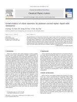
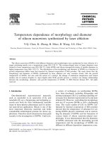
The indium droplet distribution on the substrate before
silicon evaporation appeared to be very inhomogeneous
when a desorption step had been carried out (Fig. 1). Large
droplets with diameters of about 10–20 mm and with
density of about 600 mm
À2
, as well as many tiny indium
deposits of sizes below 100 nm, located in the free space
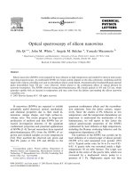
between the larger droplets, were observed. When the
desorption step was omitted, the distribution was seen to
be much more homogeneous with droplet diameters of
about 200 nm and density of about 7.7 Â 10
6
mm
À2
(Fig. 2).
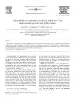
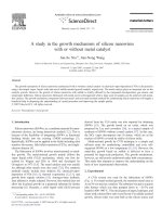
The gold distribution after a desorption step was
examined by scanning electron microscopy (SEM) and
transmission elect ron microscopy (TEM) measurements
(Fig. 3). Again, different sizes of droplets were detected.
The larger ones had diameters of about 100 nm and a
density of about 1.5 Â 10
6
mm
À2
, which can be seen in the
SEM image.
But in contrast to the indium experiments, the distribu-
tion of gold droplets did not change when skipping the
desorption step.
Zakharov et al. [8] also found an inhomogeneous
distribution of gold droplets in the range between 10 and
300 nm under comparable experimental conditions.
To explain differences in droplet formation between
indium and gold, we will consider in the following the
effects of different diffusion coefficients of gold and indium
on silicon, the solubility of substrate atoms in the two
metals, the surface tension of gold and indium and the
surface energy of silicon and silicon oxide.
The diffusion coefficients at temperatures around 550 1C
for indium and gold on a clean Si(1 1 1) surface are 0.30
and 0.12 m
2
/s, respectively [9,10]. They are of the same
order of magnitude and thus cannot account for our very
different experimental results.
We believe that a thin oxide layer forms during in-
sertion of the sample into the UHV chamber in spite
of the preceding HF-dip. There are hints in the literature
[11] that deposition of gold onto a thin layer of SiO
2
on
Si(1 1 1) favors the decomposition of SiO
2
, i.e. that gold
contributes to cleaning the surface. This could explain
why the gold distribution is the same with or without
desorption step.
Unfortunately, no literature data about the enhancement
of decomposition of a silicon oxide layer by indium were
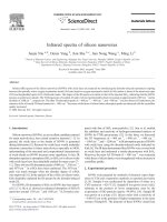
found. From the phase diagrams In–Si and Au–Si (Fig. 4 ),
it can be seen that the solubilities of silicon in gold and
indium at our growth temperatures are 420 and
o1 mol%, respectively. It could be argued that also the
solubilities of SiO
x
in gold and indium are significantly
different and thus that indium does not enhance the
decomposition of an oxide layer. If this is actually the case,
the indium distribution will then depend on whether a
desorption step has been applied or not.
Let us consider now the role of surface tension and
surface energy of the different components of our
experiment. From the phase diagram Au–Si, we expect to
have a liquid Au–Si alloy at our growth temperatures with
a silicon concentration of about 25 mol%. For this
concentration, Naidich et al. [12] found a surface tension
of about 1.0 J/m
2
at 1500 1C. No data could be found in the
literature for the surface tension of indium–silicon alloys.
However, as the solubility of silicon in indium at our
growth temperature is less than 1 mol%, we take the
surface tension of pure indium as an approximation which
is 0.6 J/m
2
at its melting point (157 1C) [13]. As the surface
tension of most liquids decreases in a nearly linear fashion
with increasing temperature [14], there is a wide difference
between the surface tension of the Au–Si alloy and the
In–Si alloy at our growth temperatures.
ARTICLE IN PRESS
Fig. 1. SEM image of the indium droplet distribution after a desorption
step had been carried out.
Fig. 2. SEM image of the indium droplet distribution when the desorption
step had been skipped.
A. Kramer et al. / Physica E 40 (2008) 2462–2467 2463
Since the state of the substrate surface a fter desorption
and the vacuum conditions are the same during evapora-
tion of gold and indium, the different liquid–solid–vapor
interface dynamics can be ascribed to the surface tension of
the solvent. Liquids with high surface tension tend to form
droplets with a small contact area with the underlying
substrate whereas liquids with lower surface tension tend to
wet the substrate. This cou ld explain the formation of
smaller droplets in the case of gold than in the case of
indium on a bare silicon surface, i.e. after desorption step
for indium.
Without desorption step, indium forms smaller droplets
which can be explained by the different surface energies of
silicon and silicon oxide. The surface energy of silicon at its
melting temperature (1410 1C) is 0.9 J/m
2
and it decreases
in a nearly linear way with increasing temperature [13], i.e.
it is higher than 0.9 J/m
2
at our growth temperatures. As we
do not know the exact composition of the surface after
inserting the sample into our growth chamber, we take data
of similar surfaces from the literature as an approximation.
Asay and Kim [15] expect the surface energy of a not
exactly specified silicon oxide surface to be higher than
0.1 J/m
2
at room temperature. Janczuk and Zdziennicka
[16] determined the surface energy of quartz in the
temperature range from 200 to 1000 1C and found out
that it chang ed only slightly from 0.19 to 0.18 J/m
2
. This
indicates that the silicon oxide surface energy is always
smaller than the silicon surface energy which is not
surprising if one thinks of a crystalline silicon surface and
an amorphous oxide surface. This explains why the bare
silicon tends to minimize the free surface by maximizing the
contact area between indium and silicon. This leads to
larger droplets compared to those on the silicon oxide
surface.
The size and distribution of gold and indium droplets on
the silicon surface that we observed by SEM and TEM
after cooling down (Figs. 1–3) may be therefore reasonably
explained considering the influence of solubilities and
surface energies on the mechanism of formation of droplets
with or without desorption step.
Silicon nanowires were obtained after silicon evapora-
tion on substrates with indium and on those with gold.
Without desorption step, however, no wire growth from
indium could be realized. Furthermore, the results with
indium and gold differed in direction and distribution of
the wires.
The sample where indium was used as solvent showed no
wire growth from the large droplets, while in the space
between, a not completely closed silicon layer was found.
In the cavities of this layer, silicon nanowires appeared
sporadically (Fig. 5).
ARTICLE IN PRESS
Fig. 3. TEM and SEM images of the gold distribution on a sample. The arrows indicate different sizes of droplets.
1500
1200
900
600
300
0
0
0.2 0.4
0.6 0.8 1
mole Si/(Si+In)
1500
1200
900
600
300
0
0 0.2 0.4 0.6 0.8 1
mole Si/(Si+Au)
T (C) T (C)
Fig. 4. Binary phase diagrams; top: In–Si and bottom: Au–Si.
A. Kramer et al. / Physica E 40 (2008) 2462–24672464
Schmidt [17] studied, among other metals, indium as
solvent for silicon nanowire growth. He applied an HF -dip
before inserting the samples into a UHV chamber but did
not apply any other cleaning steps. He got a homogeneous
droplet distribution by annealing 4 nm of indium at a
growth temperature of 570 1C. He did not get any
nanowires after flooding the chamber with diluted silane
and explained the absence of nanowires by considering the
surface tension of indium and the low solubility of silicon
in indium.
Iacopi et al. [18] also studied indium as solvent for CVD
growth of silicon nanowires. They treated the samples by
H
2
plasma after electrodeposition of indium nanoparticles
to reduce the surface oxidation of the metals as well as of
the substrate and they obtained in this way silicon
nanowires.
Apart from CVD-based reports, no other works on the
growth of silicon nanowires from indium by means of PVD
were found.
In our case, the growth of nanowires from indium seems
to be rather insensitive to change of parameters like sub-
strate temperature, rate of metal and silicon evaporation.
On the other hand, very regular nanowires in [1 1 1]
direction were obtained on the samples where gold was
used as solvent (Fig. 6 ). In this case, we found unambig-
uous correlations between experimental parameters and
grown wires: at higher substrate temperatures, larger
droplets of several 100 nm formed and led to thicke r
nanowires, a higher gold evaporation rate led to smaller
distances between the wires and a higher silicon evapora-
tion rate led to a higher growth rate. Wires also grew when
we did not perform the desorption step, which also
corroborates the theory that gold is able to solve a thin
surface oxide layer.
There are also reports in the literature where nanowires
are grown by CVD with gold as solvent on a thick oxide
layer [19]. We also performed experiments with gold on a
100 nm thick thermal oxide grown on silicon to find out
whether nanowires are growing or not. However, we did
not get an y nanowires. Consequently, nanowire growth, at
least under our experimental conditions, is only possible on
a crystalline substrate, which again indicates that gold
dissolves the thin native oxide on the ‘‘non-desorbed’’
substrate.
To obtain a defined positioning of metal droplets, and
thus a regular arrangement of nanowires, a reproducible
process for the localization of single metal droplets in pre-
structured nanopores was successfully developed in the
course of this work. FIB treatment was applied to silicon
substrates before metal evaporation. By adjusting metal
evaporation rate and substrate tempe rature, ind ividual
indium or gold droplets formed preferentially within the
pre-structured pores (Figs. 7 and 8).
For indium, this was only possibl e when we skipped
the desorption step. After application of the desorption
step, indium aggregates were found to be distributed
randomly on the structured area, with no relation to the
position of the nanopores. By contrast, when we skipped
the desorption step, tiny indium droplets formed in the
nanopores. This is in good agreement with the previous
considerations about surface energies of silicon and silicon
oxide. The conclusion of our experiments is that it is not
possible to stabilize small indium droplets for silicon
nanowhisker growth by pre-structuring substrates when a
desorption step is carried out.
ARTICLE IN PRESS
Fig. 5. SEM images of a sample with indium as solvent after silicon deposition; left: overview of the sample and right: silicon nanowire grown in a cavity
of the not completely closed silicon layer.
Fig. 6. SEM image of a sample with gold as solvent after silicon
deposition.
A. Kramer et al. / Physica E 40 (2008) 2462–2467 2465
On the other hand, gold droplets could be well-
distributed into nanopores after de sorption.
As a next step, we tried to grow silicon nanowires from
ordered gold droplets. It was actually possible to grow
silicon nanowires in [1 1 1] direction from droplets which
had formed in the pre-structured nanopores (Fig. 8). The
successful growth of nanowires from the droplets em-
bedded in the pores also means that the lattice planes which
had been damaged by FIB bombardment could be healed
during the growth process. A recovery of the crystalline
structure around the pores is therefore possible even at the
relatively low temperatures used for the wire growth.
4. Conclusions
The different behavior of gold and indium on Si(1 1 1)
has been described and analyzed. An explanation based on
differences of solubilities of surface atoms in gold and
indium and on the different surface energies of the bare and
oxidized substrate as well as on the surface tension of the
liquid metal alloys has been presented.
Silicon nanowires have been grown via VLS mechanism
with the use of gold and indium as solvent. Indium would
be a favorable alternative for later electronic applications.
Wires from indium could only be grown when an oxide
desorption step had been applied before indium and silicon
evaporation.
The mechanism of wire growth from indium could not
be completely understood whereas wire growth from gold
was well reproducible and could be perfectly governed by
the parameters of the experiment.
A method to obtain a defined arrangement of the wires
was successfully developed. It consisted in generating
nanopores via FIB treatment on the substrate surface
where metal droplets then preferentially formed. Wire
growth from an ordered array of gold droplets was
successfully performed.
Acknowledgement
The authors thank T. Remmele for the TEM measure-
ments.
References
[1] Y. Huang, C.M. Lieber, Pure Appl. Chem. 76 (2004) 2051.
[2] R. Agarwal, C.M. Lieber, Appl. Phys. A 85 (2006) 209.
ARTICLE IN PRESS
Fig. 7. Distribution of indium on a pre-structured substrate; top: after
desorption and bottom: without desorption.
Fig. 8. SEM images of structured substrates; top: nanopores on a silicon
substrate, middle: gold droplets in nanopores, and bottom: nanowires
grown from gold droplets in nanopores.
A. Kramer et al. / Physica E 40 (2008) 2462–24672466
[3] P.D. McGary, L.W. Tan, J. Zou, B.J.H. Stadler, P.R. Downey,
A.B. Flatau, J. Appl. Phys. 99 (2006) 08B310.
[4] E.P.A.M. Bakkers, M.T. Borgstrom, M.A. Verheijen, MRS Bull. 32
(2007) 117.
[5] P. Werner, N.D. Zakharov, G. Gerth, L. Schubert, U. Goesele, Int. J.
Mater. Res. 97 (2006) 1008.
[6] S.P. Anthony, J.I. Lee, J.K. Kim, Appl. Phys. Lett. 90 (2007) 103107.
[7] W. Kern, D.A. Puotinen, RCA Rev. 31 (1970) 187.
[8] N.D. Zakharov, P. Werner, G. Gerth, L. Schubert, L. Sokolov,
U. Go
¨
sele, J. Cryst. Growth 290 (2006) 6–10.
[9] C.E. Allen, R. Ditchfield, E.G. Seebauer, J. Vac. Sci. Technol. A 14
(1996) 22.
[10] Y.L. Gavrilyuk, V.G. Lifshits, Physics, Chem. Mech. Surf. 2 (1984)
1091.
[11] W. Jun, C.E.J. Mitchell, R.G. Egdell, J.S. Foord, Surf. Sci. 506 (2002)
66.
[12] Y.V. Naidich, V. Zhuravlev, N. Krasovskaya, Mater. Sci. Eng. A 245
(1998) 293.
[13] L.Z. Mezey, J. Giber, J. Appl. Phys. 21 (1982) 1569.
[14] Ch. Wohlfahrt, B. Wohlfahrt, Landolt-Bo
¨
rnstein New Series IV/16
(1997) 3.
[15] D.B. Asay, S.H. Kim, J. Chem. Phys. 124 (2006) 174712.
[16] B. Janczuk, A. Zdziennicka, J. Mater. Sci. 29 (1994) 3559.
[17] V. Schmidt, Dissertation, 2006, p. 22 /liothek.
uni-halle.de/diss-online/06/07H002/of_index.htmS.
[18] F. Iacopi, P.M. Vereecken, M. Schaekers, M. Caymax, N. Moelans,
B. Blanpain, C. Detavernier, J. D’Haen, H. Griffiths, Mater. Res.
Soc. Symp. Proc. 1017 (2006) 1017-DD01-10-EE01-10.
[19] W.M. Weber, G.S. Duesberg, A.P. Graham, M. Liebau, E. Unger,
C. Cheze, L. Geelhaar, P. Lugli, H. Riechert, F. Kreupl, Phys. Status
Solidi B 243 (2006) 3340.
ARTICLE IN PRESS
A. Kramer et al. / Physica E 40 (2008) 2462–2467 2467