radio and receiver projects for the evil genius
Bạn đang xem bản rút gọn của tài liệu. Xem và tải ngay bản đầy đủ của tài liệu tại đây (7.89 MB, 299 trang )
22 Radio Receiver
Projects for the Evil
Genius
Evil Genius Series
Bionics for the Evil Genius: 25 Build-it-Yourself Projects
Electronic Circuits for the Evil Genius: 57 Lessons with Projects
Electronic Gadgets for the Evil Genius: 28 Build-it-Yourself Projects
Electronic Games for the Evil Genius
Electronic Sensors for the Evil Genius: 54 Electrifying Projects
50 Awesome Auto Projects for the Evil Genius
50 Model Rocket Projects for the Evil Genius
Mechatronics for the Evil Genius: 25 Build-it-Yourself Projects
MORE Electronic Gadgets for the Evil Genius: 40 NEW Build-it-Yourself Projects
101 Spy Gadgets for the Evil Genius
123 PIC
®
Microcontroller Experiments for the Evil Genius
123 Robotics Experiments for the Evil Genius
PC Mods for the Evil Genius
Solar Energy Projects for the Evil Genius
25 Home Automation Projects for the Evil Genius
51 High-Tech Practical Jokes for the Evil Genius
TOM PETRUZZELLIS
22 Radio Receiver
Projects for the
Evil Genius
New York Chicago San Francisco Lisbon London Madrid
Mexico City Milan New Delhi San Juan Seoul
Singapore Sydney Toronto
Copyright © 2008 by The McGraw-Hill Companies, Inc. All rights reserved. Manufactured in the United States of America. Except as permitted under
the United States Copyright Act of 1976, no part of this publication may be reproduced or distributed in any form or by any means, or stored in a
database or retrieval system, without the prior written permission of the publisher.
0-07-159475-2
The material in this eBook also appears in the print version of this title: 0-07-148929-0.
All trademarks are trademarks of their respective owners. Rather than put a trademark symbol after every occurrence of a trademarked name, we use
names in an editorial fashion only, and to the benefit of the trademark owner, with no intention of infringement of the trademark. Where such desig-
nations appear in this book, they have been printed with initial caps.
McGraw-Hill eBooks are available at special quantity discounts to use as premiums and sales promotions, or for use in corporate training programs.
For more information, please contact George Hoare, Special Sales, at or (212) 904-4069.
TERMS OF USE
This is a copyrighted work and The McGraw-Hill Companies, Inc. (“McGraw-Hill”) and its licensors reserve all rights in and to the work. Use of this
work is subject to these terms. Except as permitted under the Copyright Act of 1976 and the right to store and retrieve one copy of the work, you may
not decompile, disassemble, reverse engineer, reproduce, modify, create derivative works based upon, transmit, distribute, disseminate, sell, publish
or sublicense the work or any part of it without McGraw-Hill’s prior consent. You may use the work for your own noncommercial and personal use;
any other use of the work is strictly prohibited. Your right to use the work may be terminated if you fail to comply with these terms.
THE WORK IS PROVIDED “AS IS.” McGRAW-HILL AND ITS LICENSORS MAKE NO GUARANTEES OR WARRANTIES AS TO THE
ACCURACY, ADEQUACY OR COMPLETENESS OF OR RESULTS TO BE OBTAINED FROM USING THE WORK, INCLUDING ANY
INFORMATION THAT CAN BE ACCESSED THROUGH THE WORK VIA HYPERLINK OR OTHERWISE, AND EXPRESSLY DISCLAIM
ANY WARRANTY, EXPRESS OR IMPLIED, INCLUDING BUT NOT LIMITED TO IMPLIED WARRANTIES OF MERCHANTABILITY OR
FITNESS FOR A PARTICULAR PURPOSE. McGraw-Hill and its licensors do not warrant or guarantee that the functions contained in the work will
meet your requirements or that its operation will be uninterrupted or error free. Neither McGraw-Hill nor its licensors shall be liable to you or anyone
else for any inaccuracy, error or omission, regardless of cause, in the work or for any damages resulting therefrom. McGraw-Hill has no
responsibility for the content of any information accessed through the work. Under no circumstances shall McGraw-Hill and/or its licensors be liable
for any indirect, incidental, special, punitive, consequential or similar damages that result from the use of or inability to use the work, even if any of
them has been advised of the possibility of such damages. This limitation of liability shall apply to any claim or cause whatsoever whether such claim
or cause arises in contract, tort or otherwise.
DOI: 10.1036/0071489290
Thomas Petruzzellis is an electronics engineer
currently working at the geophysical laboratory at
the State University of New York, Binghamton.
Also an instructor at Binghamton, with 30 years’
experience in electronics, he is a veteran author
who has written extensively for industry
publications, including Electronics Now, Modern
Electronics, QST, Microcomputer Journal, and
Nuts & Volts. Tom wrote five previous books,
including an earlier volume in this series,
Electronic Sensors for the Evil Genius. He is also
the author of Create Your Own Electronics
Workshop; STAMP 2 Communications and Control
Projects; Optoelectronics, Fiber Optics, and Laser
Cookbook; Alarm, Sensor, and Security Circuit
Cookbook, all from McGraw-Hill. He lives in
Vestal, New York.
About the Author
About the Author
Copyright © 2008 by The McGraw-Hill Companies, Inc. Click here for terms of use.
This page intentionally left blank
Acknowledgments
I would like to thank the following people and
companies listed below for their help in making
this book possible. I would also like to thank
senior editor Judy Bass and all the folks at
McGraw-Hill publications who had a part in
making this book possible. We hope the book will
inspire both radio and electronics enthusiasts to
build and enjoy the radio projects in this book.
Richard Flagg/RF Associates
Wes Greenman/University of Florida
Charles Higgins/Tennessee State University
Fat Quarters Software
Radio-Sky Publishing
Ramsey Electronics
Vectronics, Inc
Russell Clift
Todd Gale
Eric Vogel
Acknowledgments
Copyright © 2008 by The McGraw-Hill Companies, Inc. Click here for terms of use.
This page intentionally left blank
ix
Project 10 Experiments
Acknowledgments vii
Introduction xi
1 Radio Background and History 1
2 Identifying Components and Reading 12
Schematics
3 Electronic Parts Installation and 25
Soldering
4 AM, FM, and Shortwave Crystal 39
Radio Projects
5 TRF AM Radio Receiver 49
6 Solid-State FM Broadcast Receiver 59
7 Doerle Single Tube Super-Regenerative 70
Radio Receiver
8 IC Shortwave Radio Receiver 81
9 80/40 Meter Code Practice Receiver 94
10 WWV 10 MHz “Time-Code” Receiver 104
11 VHF Public Service Monitor 116
(Action-Band) Receiver
12 6 & 2-Meter Band Amateur 127
Radio Receiver
13 Active and Passive Aircraft Band 140
Receivers
14 VLF or Very Low Frequency 153
Radio Receiver
15 Induction Loop Receiving System 165
16 Lightning Storm Monitor 175
17 Ambient Power Receiver 186
18 Earth Field Magnetometer Project 192
19 Sudden Ionospheric Disturbance 203
(SIDs) Receiver
20 Aurora Monitor Project 212
21 Ultra-Low Frequency (ULF) Receiver 224
22 Jupiter Radio Telescope Receiver 233
23 Weather Satellite Receiver 246
24 Analog to Digital Converters (ADCs) 262
Appendix: Electronic Parts Suppliers 273
Index 277
Contents
For more information about this title, click here
This page intentionally left blank
Introduction
xi
22 Radio Receiver Projects for the Evil Genius
was created to inspire readers both young and old
to build and enjoy radio and receiver projects, and
perhaps propel interested experimenters into a
career in radio, electronics or research. This book
is for people who are interested in radio and
electronics and those who enjoy building and
experimenting as well as those who enjoy research.
Radio encompasses many different avenues for
enthusiasts to explore, from simple crystal radios to
sophisticated radio telescopes. This book is an
attempt to show electronics and radio enthusiasts that
there is a whole new world “out there” to explore.
Chapter 1 will present the history and
background and elements of radio, such as
modulation techniques, etc. Chapter 2 will help the
newcomers to electronics, identifying components
and how to look and understand schematics vs.
pictorial diagrams. Next, Chapter 3 will show the
readers how to install electronic components onto
circuit boards and how to correctly solder before
embarking on their new radio building adventure.
We will start our adventure with the simple
“lowly” crystal radio in Chapter 4. Generally
crystal radios are only thought of as simple AM
radios which can only pickup local broadcast
stations. But did you know that you can build
crystal radios which can pickup long-distance
stations as well as FM and shortwave broadcasts
from around the world? You will learn how to
build an AM, FM and shortwave crystal radio, in
this chapter.
In Chapter 5, you will learn how AM radio is
broadcast, from a radio station to a receiver in your
home, and how to build your own TRF or Tuned
Radio Frequency AM radio receiver. In Chapter 6,
we will discover how FM radio works and how to
build an FM radio with an SCA output for
commercial free radio broadcasts.
Chapter 7 will present the exciting world of
shortwave radio. Shortwave radio listening has a
large following and encompasses an entire hobby
in itself. You will be able to hear shortwave
stations from around the world, including China,
Russia, Italy, on your new shortwave broadcast
receiver. Old time radio buffs will be interested in
the single tube Doerle super-regenerative
shortwave radio.
If you are interested in a portable shortwave
receiver that you could take on a camping trip,
then you may want to construct the multi-band
integrated circuit shortwave radio receiver
described in Chapter 8.
If you are interested in Amateur Radio or are
thinking of learning Morse code or want to
increase your code speed, you may want to
consider building this 80 and 40-meter code
receiver. This small lightweight portable receiver
can be built in a small enclosure and taken on
camping trips, etc.
In Chapter 10, you will learn how to build and
use a WWW time code receiver, which can be used
to pick up time signal broadcast from the National
Institute of Standards and Technology (NIST) or
Copyright © 2008 by The McGraw-Hill Companies, Inc. Click here for terms of use.
National Atomic Time Clock in Boulder CO. Time
signal broadcasts present geophysical and
propagation forecasts as well as marine and sea
conditions. They will also help you set the time on
your best chronometer.
With the VHF Public service receiver featured in
Chapter 11, you will discover the high frequency
“action bands” which cover the police, fire, taxis,
highway departments and marine frequencies. You
will be able to listen-in to all the exciting
communications in your hometown.
The 6-meter and 2-meter dual VHF Amateur
Radio receiver in Chapter 12 will permit to
discover the interesting hobby of Amateur Radio.
The 6-meter and 2-meter ham radio bands are two
of the most popular VHF bands for technician
class licensees. You may discover that you might
just want to get you own ham radio license and
talk to ham radio operators through local VHF
repeaters or to the rest of the world.
Why not build an aircraft radio and listen-in to
airline pilots talking from 747s to the control tower
many miles away. You could also build the passive
Air-band radio which you use to listen-in to your
pilot during your own flight. Passive aircraft radios
will not interfere with airborne radio so they are
permitted on airplanes, without restriction. Check
out these two receivers in Chapter 13.
Chapter 14 will also show you how to build an
induction communication system, which will allow
you to broadcast a signal around home or office
using a loop of wire, to a special induction
receiver. The induction loop broadcast system is a
great aid to the hearing impaired, since it can
broadcast to hearing aids as well.
The VLF, or “whistler” radio in Chapter 15, will
pickup very very low frequency radio waves from
around the world. You will be able to listen to low
frequency beacon stations, submarine
transmissions and “whistlers” or the radio waves
created from electrical storms on the other side of
the globe. This project is great for research
projects where you can record and later analyze
your results by feeding your recorded signal into a
sound card running an FFT program. Use your
computer to record and analyze these interesting
signals. There are many free programs available
over the Internet. An FFT audio analyzer program
can display the audio spectrum and show you
where the signals plot out in respect to frequency.
If you are interested in weather, then you will
appreciate the Lightening to Storm Receiver in
Chapter 16, which will permit you to “see” the
approaching storm berfore it actually arrives. This
receiver will permit you to have advanced warning
up to 50 miles or more away; it will warn you well
in advance of an electrical storm, so you can
disconnect any outdoor antennas.
The Ambient Power Module receiver project
illustrated in Chapter 17, will allow to you pickup
a broad spectrum of radio waves which get
converted to DC power, and which can be used to
power low current circuits around your home or
office. This is a great project for experimentation
and research. You can use it to charge cell phones,
emergency lights, etc.
Our magnetometer project shown in Chapter 18
can be used to see the diurnal or daily changes in
the Earth’s magnetic field, and you can record the
result to a data-logger or recording multi-meter.
If you are an avid amateur radio operator or
shortwave listener, you many want to build a SIDs
receiver shown in Chapter 19. A SIDs receiver can
be used to determine when radio signals and/or
propagation is disturbed by solar storms. This
receiver will quickly alert you to unfavorable radio
conditions. You can collect the receiver to your
personal computer’s sound card and use the data
recorded to correlate radio propagation against
storm conditions.
The Aurora receiver project in Chapter 20 will
alert you, with both sound and meter display, when
the Earth’s magnetic increases just before an
Aurora display is about to take place. UFO and
Alien contact buffs can use this receiver to know
when UFOs are close by.
xii
Introduction
xiii
For those interested in more earthly research
projects, why not build your own ULF or ultra low
frequently receiver, shown in Chapter 21, which
can be utilized for detecting low frequency wave
generated by earthquakes and fault lines. With this
receiver you will be able to conduct your own
research projects on monitoring the pulse of the
Earth. You can connect your ELF receiver to a
data-logger and record the signals over time to
correlate your research with that of others.
You can explore the heavens by constructing
your own radio telescope to monitor the radio
signals generated from the planet Jupiter. This
radio receiver, illustrated in Chapter 22, will pick
up radio signals which indicate electrical and or
magnetic storms on the Jovian planet. The Radio
Jupiter receiver can be coupled to your personal
computer, and can be used for a research project to
record and analyze these radio storm signals.
Why not construct your own weather satellite
receiving station, shown in Chapter 23. This
receiver will allow you to receive APT polar
satellites broadcasting while passing overhead. You
can display the satellite weather maps on the
computer’s screen or save them later to show
friends and relatives.
Chapter 24 discusses different analog to digital
converters which you can use to collect and record
data from the different receiver projects.
We hope you will find the 22 Radio Projects for
the Evil Genius a fun and thought-provoking book,
that will find a permanent place on your
electronics or radio bookshelf. Enjoy!
Introduction
This page intentionally left blank
22 Radio Receiver
Projects for the Evil
Genius
This page intentionally left blank
Radio Background and History
Chapter 1
Electromagnetic energy encompasses an extremely wide
frequency range. Radio frequency energy, both natural
radio energy created by lightning and planetary storms
as well as radio frequencies generated by man for
communications, entertainment, radar, and television
are the topic of this chapter. Radio frequency energy,
or RF energy, covers the frequency range from the low
end of the radio spectrum, around l0 to 25 kHz, which
is used by high-power Navy stations that communicate
with submerged nuclear submarines, through the
familiar AM broadcast band from 550 to 1600 kHz.
Next on the radio frequency spectrum are the shortwave
bands from 2000 kHz to 30,000 kHz. The next band of
frequencies are the very high frequency television
channels covering 54 to 2l6 MHz, through the very
popular frequency modulation FM band from 88 to
l08 MHz. Following the FM broadcast band are aircraft
frequencies on up through UHF television channels and
then up through the radar frequency band of 1000 to
1500 MHz, and extending through approximately
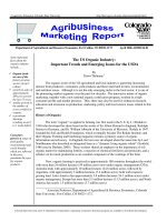
300 gHz. See frequency spectrum chart in Figure 1-1.
The radio frequency spectrum actually extends almost
up to the lower limit of visible light frequencies.
Radio history
One of the more fascinating applications of electricity is
in the generation of invisible ripples of energy called
radio waves. Following Hans Oersted’s accidental
discovery of electromagnetism, it was realized that
electricity and magnetism were related to each other.
When an electric current was passed through a conductor,
a magnetic field was generated perpendicular to the axis
of flow. Likewise, if a conductor was exposed to a
change in magnetic flux perpendicular to the conductor,
a voltage was produced along the length of that
conductor.
Joseph Henry, a Princeton University professor, and
Michael Faraday, a British physicist, experimented
separately with electromagnets in the early 1800s. They
each arrived at the same observation: the theory that a
current in one wire can produce a current in another
wire, even at a distance. This phenomenon is called
electromagnetic induction, or just induction. That is,
one wire carrying a current induces a current in a
second wire. So far, scientists knew that electricity
and magnetism always seemed to affect each other at
right angles. However, a major discovery lay hidden
just beneath this seemingly simple concept of related
perpendicularity, and its unveiling was one of the
pivotal moments in modern science.
The man responsible for the next conceptual
revolution was the Scottish physicist James Clerk
Maxwell (1831–1879), who “unified” the study of
electricity and magnetism in four relatively tidy
equations. In essence, what he discovered was that
electric and magnetic fields were intrinsically related
to one another, with or without the presence of a
conductive path for electrons to flow. Stated more
formally, Maxwell’s discovery was this: a changing
electric field produces a perpendicular magnetic field,
and a changing magnetic field produces a perpendicular
electric field. All of this can take place in open space,
the alternating electric and magnetic fields supporting
each other as they travel through space at the speed of
light. This dynamic structure of electric and magnetic
fields propagating through space is better known as an
electromagnetic wave.
Later, Heinrich Hertz, a German physicist, who is
honored by our replacing the expression “cycles per
second” with hertz (Hz), proved Maxwell’s theory
between the years 1886 and l888. Shortly after that, in
1892, Eouard Branly, a French physicist, invented a
device that could receive radio waves (as we know them
today) and could cause them to ring an electric bell.
1
Copyright © 2008 by The McGraw-Hill Companies, Inc. Click here for terms of use.
2
Note that at the time all the research being conducted in
what was to become radio and later radio-electronics,
was done by physicists.
In 1895, the father of modem radio, Guglielmo
Marconi, of Italy, put all this together and developed
the first wireless telegraph and was the first to
commercially put radio into ships. The wire telegraph
had already been in commercial use for a number of
years in Europe. The potential of radio was finally
realized through one of the most memorable events
in history. With the sinking of the Titanic in 1912,
communications between operators on the sinking
ship and nearby vessels, and communications to shore
stations listing the survivors brought radio to the public
in a big way.
AM radio broadcasting began on November 2, 1920.
Four pioneers: announcer Leo Rosenberg, engineer
William Thomas, telephone line operator John Frazier
and standby R.S. McClelland, made their way to a
makeshift studio—actually a shack atop the Westinghouse
“K” Building in East Pittsburgh—flipped a switch and
began reporting election returns in the Harding vs. Cox
Presidential race. At that moment, KDKA became the
pioneer broadcasting station of the world.
Radio spread like wildfire to the homes of everyone
in America in the 1920s. In a few short years, over
75 manufacturers began selling radio sets. Fledgling
manufacturers literally came out of garages over-night.
Many young radio enthusiasts rushed out to buy parts
and radio kits which soon became available.
Radio experimenters discovered that an amplitude-
modulated wave consists of a carrier and two identical
sidebands which are both above and below the carrier
wave. The Navy conducted experiments in which they
attempted to pass one sideband and attenuate the
other. These experiments indicated that one sideband
contained all the necessary information for voice
transmission, and these discoveries paved the way for
development of the concept of single-sideband or SSB
transmission and reception.
In 1923, a patent was granted to John R. Carson on
his idea to suppress the carrier and one sideband.
In that year the first trans-Atlantic radio telephone
demonstration used SSB with pilot carrier on a
frequency of 52 kc. Single sideband was used because of
limited power capacity of the equipment and the narrow
bandwidths of efficient antennas for those frequencies.
By 1927, trans-Atlantic SSB radiotelephony was open
for public service. In the following years, the use of SSB
was limited to low-frequency and wire applications.
Early developments in FM transmission suggested that
this new mode might prove to be the ultimate in voice
communication. The resulting slow development of SSB
technology precluded practical SSB transmission and
reception at high frequencies. Amateur radio SSB
activity followed very much the same pattern. It wasn’t
until 1948 that amateurs began seriously experimenting
with SSB, likely delayed by the wartime blackouts.
The breakthroughs in the war years, and those
following the war, were important to the development of
HF-SSB communication. Continued advances in
Chapter One: Radio Background and History
wavelength (
λ) in metres
LONG
WAVELENGTH
LOW
FREQUENCY
Radio
waves
frequency (ν
) in hertz
Radar
Microwaves
Infrared
VISIBLE LI
GHT
RED
1 m
10
4
10
4
10
6
10
8
10
10
10
12
10
14
10
16
10
18
10
20
10
22
10
2
10
−
2
10
−
4
10
−
6
10
−
8
10
−10
10
−12
10
−14
VIOLET
X-rays
Gamma
rays
SHORT
WAVELENGTH
HIGH
FREQUENCY
Ultraviolet
Figure 1-1 Electromagnetic spectrum
technology made SSB the dominant mode of HF radio
communication.
The radio-frequency spectrum, once thought to be
adequate for all needs, has become very crowded.
As the world’s technical sophistication progresses,
the requirements for rapid and dependable radio
communications increase. The competition for available
radio spectrum space has increased dramatically.
Research and development in modern radio systems has
moved to digital compression and narrow bandwidth
with highly developed modulation schemes and satellite
transmission.
The inventor most responsible for the modern day
advances in radio systems was Edwin H. Armstrong.
He was responsible for the Regenerative circuit in 1912,
the Superheterodyne radio circuit in 1918, the
Superregenerative radio circuit design in 1922 and
the complete FM radio system in 1933. His inventions
and developments form the backbone of radio
communications as we know it today. The majority of
all radio sets sold are FM radios, all microwave relay
links are FM, and FM is the accepted system in all
space communications. Unfortunately, Armstrong
committed suicide while still embittered in patent
lawsuits: later vindicated, his widow received a windfall.
Sony introduced their first transistorized radio in
1960, small enough to fit in a vest pocket, and able to
be powered by a small battery. It was durable, because
there were no tubes to burn out. Over the next 20 years,
transistors displaced tubes almost completely except for
very high power, or very high frequency, uses. In the
1970s; LORAN became the standard for radio navigation
system, and soon, the US Navy experimented with
satellite navigation. Then in 1987, the GPS constellation
of satellites was launched and navigation by radio in the
sky had a new dimension. Amateur radio operators began
experimenting with digital techniques and started to send
pictures, faxes and teletype via the personal computer
through radio. By the late 1990s, digital transmissions
began to be applied to radio broadcasting.
Types of radio waves
There are many kinds of natural radiative energy
composed of electromagnetic waves. Even light is
electromagnetic in nature. So are shortwaves, X-rays
and “gamma” ray radiation. The only difference
between these kinds of electromagnetic radiation is the
frequency of their oscillation (alternation of the electric
and magnetic fields back and forth in polarity).
By using a source of AC voltage and a device called
an antenna, we can create electromagnetic waves.
It was discovered that high frequency electromagnetic
currents in an antenna wire, which in turn result in a
high frequency electromagnetic field around the
antenna, will result in electromagnetic radiation
which will move away from the antenna into free
space at the velocity of light, which is approximately
300,000,000 meters per second.
In radio transmission, a radiating antenna is used
to convert a time-varying electric current into an
electromagnetic wave, which freely propagates through
a nonconducting medium such as air or space.
An antenna is nothing more than a device built to
produce a dispersing electric or magnetic field.
An electromagnetic wave, with its electric and magnetic
components, is shown in Figure 1-2.
When attached to a source of radio frequency signal
generator, or transmitter, an antenna acts as a transmitting
device, converting AC voltage and current into
electromagnetic wave energy. Antennas also have the
ability to intercept electromagnetic waves and convert
their energy into AC voltage and current. In this mode,
an antenna acts as a receiving device.
Radio frequencies
spectrum
Radio frequency energy is generated by man for
communications, entertainment, radar, television,
3
Chapter One: Radio Background and History
λ=Wavelength
Electric
field
Magnetic
field
Direction
Figure 1-2 Magnetic vs. electric wave
navigation, etc. This radio frequency or (RF) energy
covers quite a large range of radio frequencies from the
low end of the radio spectrum from l0 to 25 kHz, which
is the domain occupied by the high-power Navy stations
that communicate with submerged nuclear submarines:
these frequencies are called Very Low Frequency waves
or VLF. Above the VLF frequencies are the medium
wave frequencies or (MW), i.e. the AM radio broadcast
band from 550 to 1600 kHz. The shortwave bands or
High Frequency or (HF) bands cover from 2000 kHz to
30,000 kHz and make use of multiple reflections from
the ionosphere which surrounds the Earth, in order to
propagate the signals to all parts of the Earth. The Very
High Frequencies or VHF bands begin around 30 MHz;
these lower VHF frequencies are called low-band VHF.
Mid-band VHF frequencies begin around 50 MHz
which cover the lowest TV channel 2. Low-band
television channels 2 through 13 cover the 54 to 2l6 MHz
range. The popular frequency modulation or (FM)
broadcast band covers the range from 88 to l08 MHz,
which is followed by low-band Air-band frequencies
from 118 to 136 MHz. High-band VHF frequencies
around 144 are reserved for amateur radio, public service
around 150 MHz, with marine frequencies around
156 MHz. UHF frequencies begin around 300 MHz
and go up through the radar frequency band of 1000 to
1500 MHz, and extending through approximately
300 gHz. Television channels 14 through 70 are placed
between 470 and 800 MHz. American cell phone
carriers have cell phone communications around
850 MHz. Geosynchronous weather satellites signals
are placed around 1.6 GHz, and PCS phone devices
are centered around 1.8 GHz. The Super-high frequency
(SHF) bands range from 3 to 30 GHz, with C-band
microwave frequencies around 3.8 GHz, then X-band,
from 7.25 to 8.4 GHz, followed by the KA and
KU-band microwave bands.
Table 1-1 illustrates the division of radio frequencies.
The radio frequency spectrum extends almost up to the
lower limit of visible light frequencies, with just the
infrared frequencies lying in between it and visible light.
The radio frequency spectrum is a finite resource which
must be used and shared with many people and agencies
around the world, so cooperation is very important.
So how does a radio work? As previously mentioned,
radio waves are part of a general class of waves known
as electromagnetic waves. In essence, they are electrical
and magnetic energy which travels through space in the
form of a wave. They are different from sound waves
(which are pressure waves that travel through air or
water, as an example) or ocean waves (similar to sound
waves in water, but much lower in frequency and are
much larger). The wave part is similar, but the energy
involved is electrical and magnetic, not mechanical.
Electromagnetic waves show up as many things.
At certain frequencies, they show up as radio waves.
At much higher frequencies, we call them infrared light.
Still higher frequencies make up the spectrum known as
visible light. This goes on up into ultraviolet light, and
X-rays, things that radio engineers rarely have to worry
about. For our discussions, we’ll leave light to the
physicists, and concentrate on radio waves.
Radio waves have two important characteristics that
change. One is the amplitude, or strength of the wave.
This is similar to how high the waves are coming into
shore from the ocean. The bigger wave has a higher
amplitude. The other thing is frequency. Frequency is
how often the wave occurs at any point. The faster the
wave repeats itself, the higher the frequency. Frequency
is measured by the number of times in a second that the
wave repeats itself. Old timers remember when frequency
was described in units of cycles per second. In more
recent times we have taken to using the simplified term
of hertz (named after the guy who discovered radio
waves). Metric prefixes are often used, so that 1000 hertz
is a kilohertz, one million hertz is a megahertz, and so on.
A typical radio transmitter, for example, takes an
audio input signal, such as voice or music and amplifies
it. The amplified audio is in turn sent to a modulator
and an RF exciter which comprises the radio frequency
transmitter. The exciter in the transmitter generates a
main carrier wave. The RF signal from the exciter is
further amplified by a power amplifier and then the RF
signal is sent out to an antenna which radiates the signal
into the sky and out into the ionosphere. Depending
upon the type of transmitter used the modulation
technique can be either AM, FM, SSB signal sideband,
CW, or digital modulation, etc.
AM modulation
Amplitude modulation (AM) is a technique used in
electronic communication, most commonly for
transmitting information via a carrier wave wirelessly.
4
Chapter One: Radio Background and History
It works by varying the strength of the transmitted
signal in relation to the information being sent.
In the mid-1870s, a form of amplitude modulation
was the first method to successfully produce quality
audio over telephone lines. Beginning in the early
1900s, it was also the original method used for audio
radio transmissions, and remains in use by some forms
of radio communication—“AM” is often used to refer
to the medium-wave broadcast band (see AM
Radio–Chapter 5).
Amplitude modulation (AM) is a type of modulation
technique used in communication. It works by varying
5
Chapter One: Radio Background and History
Table 1-1
Radio frequency spectrum chart
Frequency range
Extremely Low Frequency (ELF) 0 to 3 kHz
Very Low Frequency (VLF) 3 kHz to 30 kHz
Radio Navigation & maritime/aeronautical mobile 9 kHz to 540 kHz
Low Frequency (LF) 30 kHz to 300 kHz
Medium Frequency (MF) 300 kHz to 3000 kHz
AM Radio Broadcast 540 kHz to 1630 kHz
Travellers Information Service 1610 kHz
High Frequency (HF) 3 MHz to 30 MHz
Shortwave Broadcast Radio 5.95 MHz to 26.1 MHz
Very High Frequency (VHF) 30 MHz to 300 MHz
Low Band: TV Band 1 - Channels 2-6 54 MHz to 88 MHz
Mid Band: FM Radio Broadcast 88 MHz to 174 MHz
High Band: TV Band 2 - Channels 7-13 174 MHz to 216 MHz
Super Band (mobile/fixed radio & TV) 216 MHz to 600 MHz
Ultra-High Frequency (UHF) 300 MHz to 3000 MHz
Channels 14-70 470 MHz to 806 MHz
L-band: 500 MHz to 1500 MHz
Personal Communications Services (PCS) 1850 MHz to 1990 MHz
Unlicensed PCS Devices 1910 MHz to 1930 MHz
Superhigh Frequencies (SHF)
(Microwave) 3 GHz to 30.0 GHz
C-band 3600 MHz to 7025 MHz
X-band 7.25 GHz to 8.4 GHz
Ku-band 10.7 GHz to 14.5 GHz
Ka-band 17.3 GHz to 31.0 GHz
Extremely High Frequencies (EHF)
(Millimeter Wave Signals) 30.0 GHz to 300 GHz
Additional Fixed Satellite 38.6 GHz to 275 GHz
Infrared Radiation 300 GHz to 430 THz
Visible Light 430 THz to 750 THz
Ultraviolet Radiation 1.62 PHz to 30 PHz
X-Rays 0.30 PHz to 30 EHz
Gamma Rays 0.30 EHz to 3000 EHz
the strength of the transmitted signal in relation to the
information being sent, for example, changes in the
signal strength can be used to reflect sounds being
reproduced in the speaker. This type of modulation
technique creates two sidebands with the carrier wave
signal placed in the center between the two sidebands.
The transmission bandwidth of AM is twice the signal’s
original (baseband) bandwidth—since both the positive
and negative sidebands are ‘copied’ up to the carrier
frequency, but only the positive sideband is present
originally. See Figure 1-3. Thus, double-sideband AM
(DSB-AM) is spectrally inefficient. The power
consumption of AM reveals that DSB-AM with its
carrier has an efficiency of about 33% which is too
efficient. The benefit of this system is that receivers are
cheaper to produce. The forms of AM with suppressed
carriers are found to be 100% power efficient, since no
power is wasted on the carrier signal which conveys no
information. Amplitude modulation is used primarily in
the medium wave band or AM radio band which covers
520 to 1710 kHz. AM modulation is also used by
shortwave broadcasters in the SW bands from between
5 MHz and 24 MHz, and in the aircraft band which
covers 188 to 136 MHz.
FM modulation
Frequency modulation (FM) is a form of modulation
which represents information as variations in the
instantaneous frequency of a carrier wave. Contrast this
with amplitude modulation, in which the amplitude
of the carrier is varied while its frequency remains
constant. In analog applications, the carrier frequency is
varied in direct proportion to changes in the amplitude
of an input signal. Digital data can be represented by
shifting the carrier frequency among a set of discrete
values, a technique known as frequency-shift keying.
The diagram in Figure 1-4, illustrates the FM modulation
scheme, the RF frequency is varied with the sound input
rather than the amplitude.
FM is commonly used at VHF radio frequencies
for high-fidelity broadcasts of music and speech,
as in FM broadcasting. Normal (analog) TV sound is
also broadcast using FM. A narrowband form is used
for voice communications in commercial and amateur
radio settings. The type of FM used in broadcast is
generally called wide-FM, or W-FM. In two-way radio,
narrowband narrow-FM (N-FM) is used to conserve
bandwidth. In addition, it is used to send signals
into space.
Wideband FM (W-FM) requires a wider bandwidth
than amplitude modulation by an equivalent modulating
signal, but this also makes the signal more robust against
noise and interference. Frequency modulation is also
more robust against simple signal amplitude fading
phenomena. As a result, FM was chosen as the
modulation standard for high frequency, high fidelity
radio transmission: hence the term “FM radio.”
FM broadcasting uses a well-known part of the VHF
band between 88 and 108 MHz in the USA.
FM receivers inherently exhibit a phenomenon
called capture, where the tuner is able to clearly
receive the stronger of two stations being broadcast on
6
Chapter One: Radio Background and History
Figure 1-3 Amplitude modulation waveform
the same frequency. Problematically, however,
frequency drift or lack of selectivity may cause one
station or signal to be suddenly overtaken by another
on an adjacent channel. Frequency drift typically
constituted a problem on very old or inexpensive
receivers, while inadequate selectivity may plague
any tuner. Frequency modulation is used on the FM
broadcast band between 88 and 108 MHz as well as in
the VHF and UHF bands for both public service and
amateur radio operators.
Single sideband (SSB)
modulation
Single sideband modulation (SSB) is a refinement upon
amplitude modulation, which was designed to be more
efficient in its use of electrical power and spectrum
bandwidth. Single sideband modulation avoids this
bandwidth doubling, and the power wasted on a carrier,
but the cost of some added complexity.
The balanced modulator is the most popular method
of producing a single sideband modulated signal. The
balanced modulator provides the “sidebands” of energy
that exist on either side of the carrier frequency but
eliminates the RF carrier, see Figure 1-5. The carrier is
removed because it is the sidebands that provide the
actual meaningful content of material, within the
modulation envelope. In order to make SSB even more
efficient, one of these two sidebands is removed by a
bandpass. So the intelligence is preserved with SSB
and it becomes a more efficient use of radio spectrum
energy. It provides almost 9 Decibels (dBs) of signal
gain over an amplitude modulated signal that includes
an RF “carrier” of the same power level! As the final
RF amplification is now concentrated in a single
sideband, the effective power output is greater than in
normal AM (the carrier and redundant sideband
account for well over half of the power output of
an AM transmitter). Though SSB uses substantially
less bandwidth and power, it cannot be demodulated
by a simple envelope detector like standard AM.
SSB was pioneered by telephone companies in the
1930s for use over long-distance lines, as part of a
technique known as frequency-division multiplexing
(FDM). This enabled many voice channels to be sent
down a single physical circuit. The use of SSB meant
that the channels could be spaced (usually) just 4000 Hz
apart, while offering a speech bandwidth of nominally
300–3400 Hz. Amateur radio operators began to
experiment with the method seriously after World War II.
It has become a de facto standard for long-distance
voice radio transmissions since then.
7
Chapter One: Radio Background and History
Figure 1-4 FM modulation waveform
Single Sideband Suppressed Carrier (SSB-SC)
modulation was the basis for all long-distance telephone
communications up until the last decade. It was
called “L carrier.” It consisted of groups of telephone
conversations modulated on upper and/or lower
sidebands of contiguous suppressed carriers. The
groupings and sideband orientations (USB, LSB)
supported hundreds and thousands of individual
telephone conversations. Single sideband communications
are used by amateur radio operators and government,
and utility stations primarily in the shortwave bands for
long-distance communications.
Shortwave radio
Shortwave radio operates between the frequencies of
1.80 MHz and 30 MHz and came to be referred to as
such in the early days of radio because the wavelengths
associated with this frequency range were shorter than
those commonly in use at that time. An alternate name is
HF or high frequency radio. Short wavelengths are
associated with high frequencies because there is an
inverse relationship between frequency and wavelength.
Shortwave frequencies are capable of reaching the other
side of the Earth, because these waves can be refracted by
the ionosphere, by a phenomenon known as Skywave
propagation. High-frequency propagation is dependent upon
a number of different factors, such as season of the year,
solar conditions, including the number of sunspots, solar
flares, and overall solar activity. Solar flares can prevent the
ionosphere from reflecting or refracting radio waves.
Another factor which determines radio propagation is
the time of the day; this is due to a particular transient
atmosphere ionized layer forming only during day when
atoms are broken up into ions by sun photons. This layer
is responsible for partial or total absorption of particular
frequencies. During the day, higher shortwave frequencies
(i.e., above 10 MHz) can travel longer distances than
lower ones; at night, this property is reversed.
Different types of modulation techniques are used on
the shortwave frequencies in addition to AM and FM.
AM, amplitude modulation, is generally used for
shortwave broadcasting, and some aeronautical
communications, while Narrow-band frequency
modulation (NFM) is used at the higher HF frequencies.
Single sideband or (SSB), is used for long-range
communications by ships and aircraft, for voice
transmissions by amateur radio operators. CW,
Continuous Carrier Wave or (CW), is used for Morse
code communications. Various other types of digital
communications such as radioteletype, fax, digital,
SSTV and other systems require special hardware and
software to decode. A new broadcasting technique
called Digital Radio Mondiale or (DRM) is a digital
modulation scheme used on bands below 30 MHz.
Shortwave listening
Many hobbyists listen to shortwave broadcasters and for
some listeners the goal is to hear as many stations from
as many countries as possible (DXing); others listen to
specialized shortwave utility, or “UTE,” transmissions
8
Chapter One: Radio Background and History
Figure 1-5 Single sideband modulation waveform