- Trang chủ >>
- Khoa Học Tự Nhiên >>
- Vật lý
facile route to the synthesis of porous - fe2o3 nanorods
Bạn đang xem bản rút gọn của tài liệu. Xem và tải ngay bản đầy đủ của tài liệu tại đây (779.4 KB, 6 trang )
Materials Chemistry and Physics 111 (2008) 438–443
Contents lists available at ScienceDirect
Materials Chemistry and Physics
journal homepage: www.elsevier.com/locate/matchemphys
Facile route to the synthesis of porous ␣-Fe
2
O
3
nanorods
Saikat Mandal, Axel H.E. M
¨
uller
∗
Makromolekulare Chemie II and Bayreuther Zentrum f
¨
ur Kolloide und Grenzfl
¨
achen, Universit
¨
at Bayreuth, D-95440 Bayreuth, Germany
article info
Article history:
Received 17 September 2007
Received in revised form 15 April 2008
Accepted 21 April 2008
Keywords:
Iron oxide
Template synthesis
Porous materials
Magnetic materials
abstract
The requirements of simple and reliable protocols for the synthesis of anisotropic structures with con-
trolled morphology continue to be a major challenge in nanoscience. In this paper we describe the facile
synthesis of porous hematite (␣-Fe
2
O
3
) nanorods usinganionic surfactant asa rod-like template. ␣-FeOOH
nanorods with diameters of 170–210 nm and lengths up to 3–5 m were synthesized in high yield via
hydrothermal method using sodium dodecyl sulphate as a template. The porous ␣-Fe
2
O
3
was obtained
after solvent extraction and calcining the as-obtained ␣-FeOOH nanorods at 500
◦
Cfor6h.Evenafter
removal of template by solvent extraction and calcination the shape of the nanorods was intact except
the generation of pores on the nanorods. The porous nanorods were analysed by X-ray diffraction (XRD),
Fourier transform infrared (FTIR) spectroscopy, transmission and high-resolution transmission electron
microscopy (TEM & HRTEM), scanning electron microscopy (SEM) and superconducting quantum inter-
ference device (SQUID) measurements. SEM and TEM images showed that the morphology of hematite
nanostructure is homogeneous in the shape of rods and full of porosity and magnetization measurements
of the porous ␣-Fe
2
O
3
nanorods showed weak ferromagnetic behavior. The surfactant SDS (sodium dode-
cyl sulphate) plays a key role in controlling the nucleation and growth of the nanorods and their use as a
new class of inorganic scaffolds for the synthesis of nanomaterials are salient features of the work with
implications in crystal engineering and nanocomposites design for various applications.
© 2008 Elsevier B.V. All rights reserved.
1. Introduction
An important area of research in nanotechnology is the develop-
ment of reliable synthesis protocols for nanostructured materials
over a range of chemical compositions, shapes and sizes. Over
the past few years, the synthesis of inorganic nanoscale materials
with special morphologies has been of great interest in mate-
rial science [1,2] because the intrinsic properties of nanoscale
materials are mainly determined by their composition, structure,
crystallinity, size, and morphology [3]. Compared with nondi-
mensional nanoparticles, one-dimensional (1D) nanomaterials are
more interesting because of their potential high technological
applications for electronics, photonics, and magnetic materials [4].
In recent years, the preparation of magnetic nanomaterials is
under scrutiny for potential applications in information storage [5],
color imaging [6], magnetic refrigeration [7] bioprocessing [8],gas
sensors [9], ferrofluids [10], and so on. In particular, hematite (␣-
Fe
2
O
3
), the most stable iron oxide, with n-type semiconducting
properties under ambient conditions, is of scientific and techno-
logical importance because of its usage in catalysts [11], sensors
∗
Corresponding author.
E-mail address: (A.H.E. M
¨
uller).
[12], and lithium-ion batteries [13]. Because of their nontoxicity,
low cost, and hue, they are also widely used as polishing mate-
rials and roof tiles and for colorants in the pigment and paint
industry [14]. ␣-Fe
2
O
3
nanorods, nanotubes and nanowires rep-
resent a class of 1D magnetic materials, in which carrier motion is
restricted in two directions so that they can exhibit unique behavior
which is significantly different from that of the bulk material and
expected essentially to improve photochemical, photophysical, and
electron-transport properties and make it an ideal candidate as a
photocatalyst and as a photoelectrode in solar energy conversion
applications [15]. In addition to the preparation of 1D nanoma-
terials, many efforts have been developed for the fabrication of
porous nanostructures with hollow interiors, owing to their spe-
cific structure, interesting properties that differ from their solid
counter parts [16–19]. The structural attribute, such as pores of
the materials can be applied as gas and heavy metal ion adsor-
bents, selective separation, support for artificial cells, light fillers,
low-dielectric-constant prosthetic materials as well as inorganic
carriers for enzyme immobilization and controlled drug delivery
[20–30]. Therefore, by combining the porous 1D nanostructure
with magnetic property, the magnetic porous nanorods can be an
ideal candidate for the multifunctional nanomaterials such as pho-
tonic crystals, host materials, accustic insulation, chemical reactors,
biomedical diagnosis agent and targeting drug delivery with MRI
0254-0584/$ – see front matter © 2008 Elsevier B.V. All rights reserved.
doi:10.1016/j.matchemphys.2008.04.043
S. Mandal, A.H.E. M
¨
uller / Materials Chemistry and Physics 111 (2008) 438–443 439
capability [31–35]. Many synthesis methods have been developed
for generating 1D ␣-Fe
2
O
3
nanostructures, such as nanorods [36],
nanowires [37], nanobelts [38], and nanotubes [39] using various
methods such as vapor–solid (VS) reaction [40], vapor–liquid–solid
growth technique [41], metalorganic chemical vapor deposition
(MOCVD) technique [42], sol–gel process [43], hard porous tem-
plates [44], ␥-irradiation method [45]. However, all these reported
methods either produced solid nanorods, nanowires or hollow nan-
otubes but without pores on the wall.
To the best of our knowledge, very few reports on the synthe-
sis of porous ␣-Fe
2
O
3
nanorods have been published to date [46].
Owing to their specific characteristics and promising applications
exploring proper methods for the synthesis of nanoscale porous ␣-
Fe
2
O
3
rods proves to be stimulating and valuable. Therefore, it is
important to develop the methods to regulate both the pore and
particle morphology in a one-dimensional structure of these mate-
rials. Surfactant-assisted methods have been widely used in the
preparation of one-dimensional structure of materials. The surfac-
tant plays an important role in determining the morphology of the
products, as surfactants have proved to be useful and versatile soft
templates that can form different conformations by self assembly
and lead to the formation of different nanostructures. The pres-
ence of a rod-like micelle of the surfactant in solution promoted
the formation of one-dimensional rod-like structures.
Herein, we report a new method for the preparation of porous
␣-Fe
2
O
3
nanorods using rod-like surfactant template and removing
the template by solvent extraction and calcination.
2. Experimental section
A surfactant-assisted synthesis procedure adopted to prepare iron oxide
nanorods with a high aspect ratio via hydrothermal process is described in the
following sections. All chemicals were analytical grade, purchased from Merck
Chemicals and used without further purification.
A typical approach employed by us is as follows: 1.28 mmol of FeCl
3
and
0.04 mmol of FeCl
2
·4H
2
O were dissolved in 1.5 mL of purified, deoxygenated water
with constant magnetic stirring for 10 min. Then this solution was added to 2.5 mL of
a 33 wt.% aqueous solution of SDS (sodium dodecyl sulphate) under N
2
atmosphere
and followed by vigorous stirring for 2 h. After 2 h stirring, 5 mL of 3M NaOH solu-
tion was introduced into the mixed solution under N
2
atmosphere with vigorous
stirring for 2 h more. After adding the NaOH solution into the reaction mixture a
brownish black-colored reaction mixture appears instantaneously. The next step for
the hydrothermal treatment, 2.5 mL of the brownish black-colored reaction mix-
ture was transferred into a 25 mL Teflon-lined autoclave and the autoclave was
sealed and heated at 120
◦
C for 24 h without shaking or stirring during the heat-
ing period and allowed to cool to room temperature naturally. After the reactions
were completed, the final yellow solid products were centrifuged and washed with
distilled water and absolute ethanol several times, and then dried at 40
◦
C under a
vacuum for 4 h. The obtained yellow solid products were collected for the follow-
ing experiments and characterization. To prepare porous hematite nanostructures,
the as-prepared rod-like iron oxide nanostructures were treated/stirred with acidic
(hydrochloric)–ethanolic solution at temperature 65
◦
C for 24 h, followed by calci-
nation at 500
◦
C with a ramping rate of 5 K min
−1
and then maintained at 500
◦
Cfor
6 h. A red-brown precipitate was collected and then washed with distilled water and
absolute ethanol for further characterization. To check the role of surfactant SDS as
template in the growth process of the colloidal particles, we carried out the same
experiment without surfactant as control experiment.
Powder X-ray diffraction (XRD) measurements of each sample were performed
on a PANalytical X-Pert Pro MRD instrument consisting of a rotating anode genera-
tor with a copper target (Cu K␣ radiation) operating at 45 kV and 40 mA. The XRD
patterns of the samples were recorded in the range from 2 =20to70
◦
with a 0.04
◦
2 step size and a 100 s count time. Fourier transform infrared (FTIR) spectra of
the as synthesized and calcined samples were recorded in the diffuse reflectance
mode on a Bruker IFS 66 V in the range of 600–4000 cm
−1
and at a resolution
of 4 cm
−1
. The as-synthesized and calcined samples were directly imaged using a
LEO 1530 field emission scanning electron microscope (FE-SEM) with a resolution
of 1 nm. Samples for field emission scanning electron microscopy (FE-SEM) were
prepared by solution-casting films onto Si wafers. Samples for TEM (transmission
electron microscopy) analysis were prepared by placing drops on carbon-coated
copper TEM grids after dispersing the samples in 2-propanol. The films on the
TEM grids were allowed to stand for 2 min, following which the extra solution was
removed using a blotting paper and the grid was allowed to dryprior to measure-
ment. TEM measurements were performed on a Zeiss CEM 902 Model instrument
operated at an accelerating voltage at 80 kV. High-resolution transmission electron
microscopy (HRTEM) measurements were performed on a LEO-922 model instru-
ment operated at an accelerating voltage at 200 kV. The magnetic properties of the
porous nanorods were examined using SQUID (superconducting quantum interfer-
ence device) (Quantum Design, MPMS-7).
3. Results and discussion
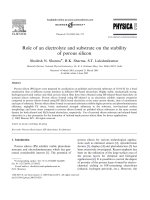
Fig. 1A shows the XRD patterns recorded in the 2 range 20–70
◦
of the samples before (curve 1) and after calcination (curve 2).
Well-defined XRD patterns were observed and all diffraction peaks
were perfectly indexed, which are in agreement with the data of
␣-FeOOH (curve 1) (JCPDS 29-713) and ␣-Fe
2
O
3
(hematite, curve
2) (JCPDS 33-664). The strong and sharp peaks indicate that the
␣-FeOOH and ␣-Fe
2
O
3
powders are highly crystalline.
Fig. 1B shows FTIR spectra of as-prepared sample, before
solvent extraction and calcination (curve 1) and sample after sol-
vent extraction and calcination (curve 2) in the spectral region
2700–3100 cm
−1
. The C–H symmetric and antisymmetric stretch-
Fig. 1. (A) The XRD patterns recorded from the as-prepared sample (curve 1) and after calcination sample (curve 2). (B) The FTIR spectra of as-prepared sample, (curve 1)
and sample after solvent extraction and calcination (curve 2).
440 S. Mandal, A.H.E. M
¨
uller / Materials Chemistry and Physics 111 (2008) 438–443
Fig. 2. (A and B) The FE-SEM images recorded from the as-prepared sample and the sample after solvent extraction and calcination, respectively. (C) The TEM image recorded
from the as-prepared sample and the inset in (C) shows the HRTEM image of the as-obtained ␣-FeOOH nanorod. (D) The HRTEM image recorded from the porous ␣-Fe
2
O
3
nanorods sample after calcination and the inset in (D) shows the magnified image of one portion of HRTEM image.
ing vibration frequencies at 2850 and 2920 cm
−1
are clearly seen
for the as-obtained ␣-FeOOH sample (before solvent extraction and
calcination), whereas after solvent extraction and calcination those
peaks are absent, which indicates that after solvent extraction and
calcination the surfactant SDS as-template has been removed.
Parts A and B of Fig. 2 show representative field emission
scanning electron microscope (FE-SEM) images recorded from
a drop-coated film of the as-prepared sample and the sample
after solvent extraction and calcination on Si wafers, respec-
tively. A densely populated, predominantly rod-like morphology
is observed (Fig. 2A) and the typical diameter and length of
the rods are estimated to be 170–210 nm and 3–5 m, respec-
tively. The FE-SEM image (Fig. 2A) shows that the surfaces of
the as-prepared nanorods (before solvent extraction and calci-
nation) are very smooth, whereas after removal of the template
by solvent extraction and calcinations, the FE-SEM micrograph
(Fig. 2B) reveals the remarkable effect on the macroscopic struc-
ture of the nanorods. The presence of nanorods with porous surface
and typical length ranging from 3–5 m and diameter of about
170–210 nm is observed. Comparing the FE-SEM images recorded
before(Fig. 2A)and after (Fig. 2B) removalof template, the nanorods
exhibit the porous surface after calcination, while the shape (length
and diameter) of the nanorods remain almost same in both the
cases (before and after template removal). The porous structure
is much more clearly seen in the FE-SEM image of the nanorods
(Fig. 2B) where the presence of relatively homogeneous pores of
9–12 nm sizes on the surface of the nanorods are observed after
calcination.
The transmission electron microscopy image recorded from the
as-prepared sample is shown in Fig. 2C and it clearly shows the
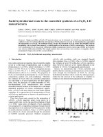
Fig. 3. The TEM image recorded from the as-prepared sample synthesized without
surfactant in control experiment.
S. Mandal, A.H.E. M
¨
uller / Materials Chemistry and Physics 111 (2008) 438–443 441
Fig. 4. (A) Magnetic hysteresis loop of the porous ␣-Fe
2
O
3
nanorods at 300 K. The inset of this figure shows a magnified view of the hysteresis loop highlighting the residual
magnetization and the coercivity. (B) Temperature dependence of ZFC and FC magnetization of the porous ␣-Fe
2
O
3
nanorods under an applied magnetic field of 500 Oe.
rod-like structure with smooth surface. The inset of Fig. 2C shows
a HRTEM image of the nanorods. The lattice planes are clearly seen
and the interplanar spacing 4.26
˚
A correspond to the (1 0 0) planes,
which reveal the crystalline nature of the as-obtained ␣-FeOOH
nanorods (before calcination). Fig. 2D shows the morphology evo-
lution that occurred during calcination of the nanorods. It reveals
that the nanorods are full of porosities and it is worth mention-
ing that the shape and size of the rods have not changed during
the calcination and there is no sign of aggregation also. HRTEM is
a powerful method for structural analysis on the atomic scale, and
thus might provide further insight into the structure of an individ-
ual ␣-Fe
2
O
3
nanorod. The HRTEM image in Fig. 2D shows that the
␣-Fe
2
O
3
rods have a porous structure with pore diameter in the
range of 9–12 nm and the inset of Fig. 2D shows that they are struc-
turally uniform with an interplanar spacing of about 3.68
˚
A, which
corresponds to the (0 1 2) plane of ␣-Fe
2
O
3
.
Fig. 3 shows the representative TEM image recorded from
a drop-cast film of the as-prepared sample obtained after the
hydrothermal synthesis in control experiment. A densely popu-
lated, predominantly irregularly shaped particles are seen that
co-exist with a small percentage of rod-shaped particles. The mor-
phologies obtained from the as-prepared sample in the control
experiment are thus totally different than that obtained from the
experiment in presence of SDS surfactant as template. It is most
likely that the rod-like micelle of the surfactant helps in the mor-
phology selectivity during the growth process.
The magnetic properties of the porous ␣-Fe
2
O
3
nanorods were
further investigated using SQUID. To investigate the magnetic
properties of the porous ␣-Fe
2
O
3
nanorods, magnetic hystere-
sis measurement was carried out in an applied magnetic field at
300 K (room temperature) with the field sweeping from −60 to
60 kOe. Fig. 4A shows the hysteresis loop of the porous nanorods.
It can be seen that saturation is not reached up to the maximum
applied magnetic field. The inset of this figure shows a magni-
fied view of the hysteresis loop recorded for the porous ␣-Fe
2
O
3
nanorods and shows weak ferromagnetic behavior with a rema-
nent magnetization of 0.02 emu g
−1
and a coercivity of 250 Oe at
room temperature (300 K). The values of the remanent magnetiza-
tion and coercivity of these porous-rod-like Fe
2
O
3
nanostructures
are higherthan those of rod-like Fe
2
O
3
(without porous) nanostruc-
Scheme 1. Schematic illustration for formation of porous nanorods using rod-like templates.
442 S. Mandal, A.H.E. M
¨
uller / Materials Chemistry and Physics 111 (2008) 438–443
tures (2.8 × 10
−3
emu g
−1
for remanent magnetization and47 Oe for
coercivity) [47]. It is well known that the magnetization of ferro-
magnetic materials is dependent on the morphology and structure
of the samples [48]. Fig. 4B shows the curves for the temper-
ature dependences of zero-field cooling (ZFC) and field cooling
(FC) magnetizations of porous ␣-Fe
2
O
3
nanorods from 2 to 390 K
under an applied magnetic field of 500 Oe. It is clearly seen that
the FC and ZFC magnetization curves split significantly; the ZFC
magnetization decreases sharply, while the FC magnetization rises
significantly. The Morin transition temperature for the porous ␣-
Fe
2
O
3
nanorods (223 K, calculated from differential ZFC curve) is
lower than that for bulk ␣-Fe
2
O
3
(263 K), which may be related to
the decrease in diameters for 1-D nanohematite, agreeing with the
theory that T
M
decreases with decreasing particle size. Because of
nanoscale confinement, nanomaterials can exhibit unusual mag-
netic behavior that is quite different from that of conventional bulk
materials.
In Scheme 1 we illustrate a possible mechanism that could
explain the formation of the rod-like morphology of iron oxide
and the formation of pores during calcination. SDS is known to
form cylindrical micelles at high concentration in solution and
it is an ionic compound, which ionizes completely in water to
form a negatively charged molecule with a long hydrophobic tail.
The first step results in a possible electrostatic interaction exist-
ing between the added Fe
3+
/Fe
2+
ions and the SDS anion, favoring
the formation of a complex in the precursor. It is expected that
on addition of the hydrolyzing agent (NaOH), very fine particles
of oxide are formed that serve as seeds and are adsorbed on the
surface of the SDS rod-like micelle. Under the hydrothermal pro-
cess, as the reaction progresses, the growth proceeds along the
active sites, resulting in the formation of elongated nanostructures
in the form of rods. We believe that because of the electrostatic
interaction of the iron ions and the anionic surfactant SDS, rod-like
conformational inorganic–surfactant composites may form, which
may serve as templates for the formation of rod-like morpholo-
gies. In the last step, the formation of porous hematite was due
to the decomposition of ␣-FeOOH to ␣-Fe
2
O
3
during calcinations
in air. It is in agreement with the topotactic reaction [49]. During
the process of the calcinations, ␣-FeOOH decomposes to ␣-Fe
2
O
3
thus we get pure hematite, which is indicated by the XRD pattern
(Fig. 1A) also.
4. Conclusions
In conclusion, it has been shown that highly porous iron oxide
rod-like structures can be formed using a rod-like micelle as
template via a hydrothermal process. Under hydrothermal condi-
tions, rod-like ␣-FeOOH nanocomposite and then, after calcination
porous ␣-Fe
2
O
3
nanorods were obtained. The detailed morphology,
crystallinity and magnetic properties of the resulting porous-
nanorods were determined using combined SEM, XRD, HRTEM and
SQUID measurements. Crystalline porous ␣-Fe
2
O
3
was obtained
after heat-treating the as-obtained ␣-FeOOH nanorods, which
retain the same nanorod morphology, even at 500
◦
C. The proposed
method has great advantages in large-scale industrial manufactur-
ing for a simple hydrothermal process, such as inexpensive raw
materials, high purity, and a high morphology yield of the products.
The surfactant SDS plays a key role in controlling the nucleation
and growth of the nanorods, and the possibility of using the ionic
surfactants as rod-like template is exciting. It is our hope that this
convenient and efficient synthesis route can be applied as a gen-
eral method for the preparation of porous 1D nanostructure of other
metal and oxides with possible applications in catalysis and novel
optical materials.
Acknowledgements
SM thanks the Alexander von Humboldt Foundation for a
research fellowship. We thank Mr. Benjamin Balke (Inorganic
Chemistry, University of Mainz, Germany) and Mr. Ram Sai Yela-
manchili (Inorganic Chemistry I, University of Bayreuth, Germany)
for the SQUID measurements and providing the hydrothermal reac-
tor, respectively.
References
[1] J.H. Fendler, F.C. Meldrum, Adv. Mater. 7 (1995) 607.
[2] B.B. Lakshmi, C.J. Patrissi, C.R. Martin, Chem. Mater. 9 (1997) 2544.
[3] Y. Sun, Y. Xia, Science 298 (2002) 2176.
[4] Y. Wu, H. Yan, M. Huang, B. Messer, J.H. Song, P. Yang, Chem. Eur. J. 8 (2002)
1260.
[5] J.C. Lodder, J. Magn. Magn. Mater. 272–276 (2004) 1692.
[6] (a) R. F. Ziolo, U.S. Patent 4,474,866 (1984);
(b) J. Oh, M.D. Feldman, J. Kim, C. Condit, S. Emelianov, T.E. Milner, Nanotech-
nology 17 (2006) 4183.
[7] (a) Y. Yang, J. Chen, J. He, E. Bruck, Physica B (Amsterdam) 364 (2005) 33;
(b) V. Franco, J.S. Bl
´
azquez, C.F. Conde, A. Conde, Appl. Phys. Lett. 88 (2006),
042505/1.
[8] N.M. Pope, R.C. Alsop, Y.A. Chang, A.K. Sonith, J. Biomed. Mater. Res. 28 (1994)
449.
[9] J.S. Han, A.B. Yu, F.J. He, T. Yao, J. Mater. Sci. Lett. 15 (1996) 434.
[10] (a) M. Kroell, M. Pridoehl, G. Zimmermann, L. Pop, S. Odenbach, A. Hartwig, J.
Magn. Magn. Mater. 289 (2005) 21;
(b) R. Keller, E. Schmidbauer, M. Hanzlik, N. Petersen, J. Magn. Magn. Mater. 162
(1996) 327.
[11] A. Brown, J. Hargreaves, B. Rijniersce, Catal. Lett. 53 (1998) 7.
[12] H T. Sun, C. Cantalini, M. Faccio, M. Pelino, M. Catalano, L. Tapfer, J. Am. Ceram.
Soc. 79 (1996) 927.
[13] (a) S. Zeng, K. Tang, T. Li, Z. Liang, D. Wang, Y. Wang, W. Zhou, J. Phys. Chem. C
111 (2007) 10217;
(b) J. Chen, L. Xu, W. Li, X. Gou, Adv. Mater. 17 (2005) 582.
[14] J. Wang, W.B. White, J.H. Adair, J. Am. Ceram. Soc. 88 (2005) 3449.
[15] T. Ohmori, H. Takahashi, H. Mametsuka, E. Suzuki, Phys. Chem. Chem. Phys. 2
(2000) 3519.
[16] S.W. Kim, M. Kim, W.Y. Lee, T. Hyeon, J. Am. Chem. Soc. 124 (2002) 7642.
[17] (a) Z. Kang, E. Wang, L. Gao, S. Lian, M. Jiang, C. Hu, L. Xu, J. Am. Chem. Soc. 125
(2003) 13652;
(b) Z. Kang, E. Wang, B. Mao, Z. Su, L. Chen, L. Xu, Nanotechnology 16 (2005)
1192.
[18] Y.G. Sun, B. Mayers, Y. Xia, Adv. Mater. 15 (2003) 641.
[19] Z.Y. Jiang, Z.X. Xie, X.H. Zhang, S.C. Lin, T. Xu, S.Y. Xie, R.B. Huang, L.S. Zheng,
Adv. Mater. 16 (2004) 904.
[20] J.J.E. Lee, J. Lee, J.H. Yu, B.C. Kim, K. An, Y. Hwang, C.H. Shin, J.G. Park, J. Kim, T.
Hyeon, J. Am. Chem. Soc. 128 (2006) 688.
[21] M. Lal, L. Levy, K.S. Kim, G.S. He, X. Wang, Y.H. Min, S. Pakatchi, P.N. Prasad,
Chem. Mater. 12 (2000) 2632.
[22] K. Sharma, S. Das, A. Maitra, J. Colloid Interface Sci. 284 (2005) 358.
[23] X. Tan, S. Liu, K. Li, J. Membr. Sci. 188 (2001) 87.
[24] N.E.Botterhuis, Q. Sun, P.C.M.M. Magusin, R.A. van Santen, N.A.J.M. Sommerdijk,
Chem. Eur. J. 12 (2006) 1448.
[25] Z.Z. Li, S.A. Xu, L.X. Wen, F. Liu, A.Q. Liu, Q. Wang, H.Y. Sun, W. Yu, J.F. Chen, J.
Controlled Release 111 (2006) 81.
[26] J.F. Chen, H.M. Ding, J.X. Wang, L. Shao, Biomaterials 25 (2004) 723.
[27] A.P.R. Johnston, B.J. Battersby, G.A. Lawrie, M. Trau, Chem. Commun. (2005) 848.
[28] Z.Z. Li, L.X. Wen, L. Shao, J.F. Chen, J. Controlled Release 98 (2004) 245.
[29] S.B. Yoon, J.Y. Kim, J.H. Kim, S.G. Park, J.Y. Kim, C.W. Lee, J S. Yu, Curr. Appl. Phys.
6 (2006) 1059.
[30] F. Caruso, R.A. Caruso, H. M
¨
ohwald, Science 282 (1998) 1111.
[31] Y. Yin, R.M. Rioux, X.K. Erdonmez, S. Hughes, G.A. Somorjai, A.P. Alivisatos,
Science 304 (2004) 711.
[32] J. Yang, L. Qi, C. Lu, J. Ma, H. Cheng, Angew. Chem. Int. Ed. 44 (2005) 598.
[33] J. Chen, F. Saeki, B.J. Wiley, H. Cang, M.J. Cobb, Z Y. Li, L. Au, H. Zhang, M.B.
Kimmey, X. Li, Y. Xia, Nano Lett. 5 (2005) 473.
[34] S. Park, J H. Lim, S W. Chung, C.A. Mirkin, Science 303 (2004) 348.
[35] Y. Sun, Y. Xia, J. Am. Chem. Soc. 126 (2004) 3892.
[36] K. Woo, H.J. Lee, J. Magn. Magn. Mater. 272-276 (2004) E1155.
[37] C. Pascal, J.L. Pascal, F. Favier, M.L.E. Moubtassim, C. Payen, Chem. Mater. 11
(1999) 141.
[38] X.G. Wen, S.H. Wang, Y. Ding, Z.L. Wang, S.H. Yang, J. Phys. Chem. B 109 (2005)
215.
[39] (a) J. Chen, L. Xu, W. Li, X. Gou, Adv. Mater. 17 (2005) 582;
(b) C H. Jia, L D. Sun, Z G. Yan, L P. You, F. Luo, X D. Han, Y C. Pang, Z. Zhang,
C H. Yan, Angew. Chem. Int. Ed. 44 (2005) 4328.
[40] (a) Y.Y. Fu, R.M. Wang, J. Xu, J. Chen, Y. Yan, A.V. Narlikar, H. Zhang, Chem. Phys.
Lett. 379 (2003) 373;
(b) Y.Y. Fu, J. Chen, H. Zhang, Chem. Phys. Lett. 350 (2001) 491.
S. Mandal, A.H.E. M
¨
uller / Materials Chemistry and Physics 111 (2008) 438–443 443
[41] Y.M. Zhao, Y H. Li, R.Z. Ma, M.J. Roe, D.G. McCartney, Y.Q. Zhu, Small 2 (2006)
422.
[42] J J. Wu, Y L. Lee, H H. Chiang, D.K P. Wong, J. Phys. Chem. B 110 (2006) 18108.
[43] C.R. Gong, D.R. Chen, X.L. Jiao, Q.L. Wang, J. Mater. Chem. 14 (2004) 905.
[44] K. Shi, Y. Chi, H. Yu, B. Xin, H. Fu, J. Phys. Chem. B 109 (2005) 2546.
[45] E.B. Gracien, Z. Ruimin, X.L. Hui, L.K. Kanza, I. Lopaka, J. Radioanal. Nucl. Chem.
270 (2006) 473.
[46] (a) C. Wu, P. Yin, X. Zhu, C.O. Yang, Y. Xie, J. Phys. Chem. B 110 (2006) 17806;
(b) S. Lian, E. Wang, Z. Kang, Y. Bai, L. Gao, M. Jiang, C. Hu, L. Xu, Solid State
Commun. 129 (2004) 485;
(c) P C. Wu, W S. Wang, Y T. Huang, H S. Sheu, Y W. Lio, T L. Tsai, D B. Shieh,
C S. Yeh, Chem. Eur. J. 13 (2007) 3878.
[47] Z. Jing, S. Wu, Mater. Lett. 58 (2004) 3637.
[48] M. Sorescu, R.A. Brand, D.M. Tarabasanu, L. Diamandescu, J. Appl. Phys. 85
(1999) 5546.
[49] (a) H. Naono, K. Nakai, T. Sueyoshi, H. Yagi, J. Colloid Interface Sci. 120 (1987)
439;
(b) H. Naono, R. Fujiwara, J. Colloid Interface Sci. 73 (1980) 406.