- Trang chủ >>
- Khoa Học Tự Nhiên >>
- Vật lý
quasi - one dimensional metal oxide semiconductors
Bạn đang xem bản rút gọn của tài liệu. Xem và tải ngay bản đầy đủ của tài liệu tại đây (3.72 MB, 67 trang )
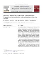
Quasi-one dimensional metal oxide semiconductors:
Preparation, characterization and application as chemical
sensors
E. Comini, C. Baratto, G. Faglia, M. Ferroni, A. Vomiero, G. Sberveglieri
*
SENSOR Lab, CNR-INFM, Dipartimento di Chimica e Fisica per l’Ingegneria e per i Materiali, Brescia University,
via Valotti 9, 25133 Brescia, Italy
article info
Article history:
Accepted 16 June 2008
abstract
The continuous evolution of nanotechnology in these years led to
the production of quasi-one dimensional (Q1D) structures in a
variety of morphologies such as nanowires, core–shell nanowires,
nanotubes, nanobelts, hierarchical structures, nanorods, nanorings.
In particular, metal oxides (MOX) are attracting an increasing
interest for both fundamental and applied science. MOX Q1D are
crystalline structures with well-defined chemical composition,
surface terminations, free from dislocation and other extended
defects. In addition, nanowires may exhibit physical properties
which are significantly different from their coarse-grained poly-
crystalline counterpart because of their nanosized dimensions.
Surface effects dominate due to the increase of their specific sur-
face, which leads to the enhancement of the surface related prop-
erties, such as catalytic activity or surface adsorption: key
properties for superior chemical sensors production.
High degree of crystallinity and atomic sharp terminations make
nanowires very promising for the development of a new genera-
tion of gas sensors reducing instabilities, typical in polycrystalline
systems, associated with grain coalescence and drift in electrical
properties. These sensitive nanocrystals may be used as resistors,
and in FET based or optical based gas sensors.
This article presents an up-to-date review of Q1D metal oxide
materials research for gas sensors application, due to the great
research effort in the field it could not cover all the interesting works
0079-6425/$ - see front matter Ó 2008 Elsevier Ltd. All rights reserved.
doi:10.1016/j.pmatsci.2008.06.003
* Corresponding author. Tel.: +39 030 3715771; fax: +39 030 2091271.
E-mail address: (G. Sberveglieri).
URL: (G. Sberveglieri).
Progress in Materials Science 54 (2009) 1–67
Contents lists available at ScienceDirect
Progress in Materials Science
journal homepage: www.elsevier.com/locate/pmatsci
reported, theonesthat,accordingto the authors,are goingto contrib-
ute to this field’s further development were selected and described.
Ó 2008 Elsevier Ltd. All rights reserved.
Contents
1. Introduction . . . . . . . . . . . . . 2
2. Deposition techniques and growth mechanisms . . . 3
2.1. Vapor phase growth . . . . . . . . . . . 4
2.1.1. Vapor–liquid–solid mechanism . . . . . . . . . 5
2.1.2. Vapor–solid mechanism. . . . . . . . . . . . . . . 9
2.2. Solution phase growth . . . . . . . . . 10
2.2.1. Template-assisted synthesis. . . . . . . . . . . . 11
2.2.2. Template-free methods . . . . . . . . . . . . . . . 12
3. Vertical and horizontal alignment techniques . . . . . 13
3.1. Electric field alignment . . . . . . . . . 18
3.2. Nanomanipulation. . . . . . . . . . . . . 21
4. Doping of quasi 1D metal oxide nanostructures . . . 22
5. Preparation of quasi 1D metal oxide heterostructures . . . . . . . . . . . . . . . . . 24
6. Applications of metal oxide nanostructures . . . . . . . 30
6.1. Metal oxide gas sensors . . . . . . . . 30
6.1.1. Surface adsorption 30
6.1.2. Detection through surface reactions . . . . . 31
6.1.3. DC resistance transduction . . . . . . . . . . . . 31
6.1.4. Conductometric gas sensors. . . . . . . . . . . . 31
6.1.5. Single nanowire transistor (SNT) based gas sensors . . . . . . . . . . . 45
6.1.6. PL based gas sensors . . . . . . . . . . . . . . . . . 50
6.2. Other application fields. . . . . . . . . 56
6.2.1. Lasers. . . . . . . . . . . 56
6.2.2. Solar cells . . . . . . . 57
6.2.3. Field emitters . . . . 57
6.2.4. Li-ion batteries . . . 59
6.2.5. Single nanowire transistors for biosensing 59
7. Conclusions. . . . . . . . . . . . . . 59
Acknowledgements . . . . . . . 60
References . . . . . . . . . . . . . . 60
1. Introduction
The increasing concerns with pollution on health and safety stress the need of monitoring all as-
pects of the environment in real time, and in turn led to a tremendous effort in terms of research
and funding for the development of sensors devoted to several applications [1–9].
As far as chemical sensing is concerned, it has been known, from more than five decades, that the
electrical conductivity of metal oxides semiconductors varies with the composition of the surrounding
gas atmosphere. The sensing properties of semiconductor metal oxides in form of thin or thick films
other than SnO
2
, like TiO
2
,WO
3
, ZnO, Fe
2
O
3
and In
2
O
3
, have been studied as well as the benefits from
the addition of noble metals – Pd, Pt, Au, Ag – in improving selectivity and stability.
In 1991 Yamazoe showed that reduction of crystallite size went along with a significant increase in
sensor performance [10]. In a nanosized grain metal oxide almost all the carriers are trapped in surface
states and only a few thermal activated carriers are available for conduction. In this configuration the
transition from activated to strongly not activated carrier density, produced by target gases species,
has a huge effect on sensor conductance. Thus, the technological challenge moved to the fabrication
of materials with small crystallize size which maintained their stability over long-term operation at
high temperature. A huge variety of devices have been developed mainly by an empirical approach
2 E. Comini et al. / Progress in Materials Science 54 (2009) 1–67
and a lot of basic theoretical research and spectroscopy studies have been carried out to improve the
well known ‘‘3S” of a gas sensor, namely sensitivity, selectivity and stability.
Nanotechnology is nowadays producing sensing materials such as quasi-1D metal oxides (MOX),
carbon nanotubes, and nano porous materials. In particular, metal oxides are an attractive and heter-
ogeneous class of active materials covering the entire range from metals to semiconductors and insu-
lators and almost all aspects of material science and physics in areas including superconductivity and
magnetism.
After the first publications demonstrating the ability of metal oxide nanowires in detecting a vari-
ety of chemical species [179,188], the interest in this research area was growing exponentially in the
past years as testified by literature.
Significant progress has been made both in terms of our fundamental understanding of the inter-
play between bulk and surface properties and processes in MOX nanowires sensors together with their
development as real world sensing platforms.
Q1D metal oxide nanostructures have several advantages with respect to traditional thin- and thick
film sensors such as very large surface-to-volume ratio, dimensions comparable to the extension of
surface charge region, superior stability owing to the high crystallinity [11], relatively simple prepa-
ration methods that allow large-scale production [14], possible functionalization of their surface with
a target-specific receptor species [190], modulation of their operating temperature to select the proper
gas semiconductor reactions, catalyst deposition over the surface for promotion or inhibition of spe-
cific reactions and finally the possibility of field-effect transistors (FET) configuration that allows the
use of gate potential controlling the sensitivity and selectivity [188].
Preparation and performances of these emerging nanosized structures have been reviewed by a
number of authors [12–15], but this research field is growing so fast that there is still the need of a
review focused on sensing applications.
This review article is focused on the description of metal oxide single crystalline Q1D nanostruc-
tures used for gas-sensing application, specifically on the promising approaches that are going to con-
tribute to the further development of this field. The overview will start from presenting the fabrication
techniques and the growth mechanisms, focusing on their development and improvements, and
pointing out the steps critical for application in real environments. Then the application as chemical
sensors will be addressed. Furthermore an outlook on other possible new applications of metal oxide
single crystalline nanowires will be presented.
2. Deposition techniques and growth mechanisms
Nanocrystalline materials can be classified into different categories depending on the number of
dimensions that are nanostructured (with dimensions lower than 100 nm); we will follow one of
the possible classification: i.e. zero dimensional for clusters, mono dimensional for nanowires and
two dimensional for films.
There are two different approaches to the production of 1D structures: top-down and bottom up
technologies.
The first one is based on standard micro fabrication methods with deposition, etching and ion beam
milling on planar substrates in order to reduce the lateral dimensions of the films to the nanometer
size. Electron beam, focused ion beam, X-ray lithography, nano-imprinting and scanning probe
microscopy techniques can be used for the selective removal processes. The advantages are the use
of the well developed technology of semiconductor industry and the ability to work on planar sur-
faces, while disadvantages are their extremely elevated costs and preparation times.
In the top-down approach highly ordered nanowires can be obtained [16–19], but at the moment
this technology does not fulfil the industrial requirements for the production of low cost and large
numbers of devices. Furthermore the 1D nanostructures produced with these techniques are in gen-
eral not single-crystalline.
The second approach, bottom-up, consists of the assembly of molecular building blocks or chemical
synthesis by vapor phase transport, electrochemical deposition, solution-based techniques or tem-
plate growth. Its advantages are the high purity of the nanocrystalline materials produced, their small
E. Comini et al. / Progress in Materials Science 54 (2009) 1–67
3
diameters, the low cost of the experimental set ups together with the possibility to easily vary the
intentional doping and the possible formation of junctions. The main disadvantage regards their inte-
gration on planar substrates for the exploitation of their useful properties, for example transfer and
contacting on transducers can be troublesome.
The bottom-up approach allows low cost fabrication although it could be very difficult to get them
well arranged and patterned [20].
Furthermore more control and insight into the growth process must be achieved for their fruitful
integration in functional devices.
The most promising approach to produce functional nanowires will be the combination of the two
preparation technologies.
This review article will be focused on the bottom-up techniques for the preparation of 1D single-
crystal nanostructures.
Numerous one-dimensional oxide nanostructures with useful properties, compositions, and mor-
phologies have recently been fabricated using bottom-up synthetic routes. Some of these structures
could not have been created easily or economically using top-down technologies.
A nomenclature for these peculiar structures has not been well established. In the literature a lot of
different names have been used, like whiskers, fibers, fibrils, nanotubules, nanocable, etc. The defini-
tion of these 1D nanostructures is not well established. A few classes of these new nanostructures with
potential as sensing devices are summarized schematically in Fig. 1. The geometrical shapes can be
tubes, cages, cylindrical wires, rods, nails, cables, belts, sheets and even more complex morphologies.
When developing 1D nanocrystals the most important requirements are dimensions and morphol-
ogy control, uniformity and crystalline properties. In order to obtain one-dimensional structures a
preferential growth direction with a faster growth rate must exists. Achieving 1D growth in systems
with a isotropic atomic bonding requires a break in the symmetry during the growth and not just stop-
ping the growth process at an early stage (0 and 2D).
In the past years the number of synthesis techniques has grown exponentially. We can divide these
growth mechanisms in different categories, first of all catalyst-free and catalyst assisted procedures
and then we can distinguish between vapor and solution phase growth. As far as metal oxides are con-
cerned the most used procedure is the vapor phase one. But solution phase growth techniques provide
a more flexible synthesis process with even lower production costs.
There are different growth mechanism depending on the presence of a catalyst, i.e. vapor–liquid–
solid (VLS), solution–liquid–solid (SLS) or vapor–solid (VS) process.
2.1. Vapor phase growth
The vapor phase approach was used in the early 60’ for the preparation of micrometer-size whis-
kers. These whiskers were prepared either by simple physical sublimation of the source material or
Fig. 1. Schematic drawing of some of the possible morphologies: (a) nanowire, (b) core–shell nanowire, (c) nanotube, (d)
nanobelt, (e) hierarchical structure, (f) nanorod and (g) nanoring.
4 E. Comini et al. / Progress in Materials Science 54 (2009) 1–67
through reduction of a volatile metal halide. In the last years this method was used to prepare differ-
ent materials in form of nanowires. The growth was performed in tubular furnace studied to obtain
the proper temperature gradient. The source material once evaporated is transported by a gas carrier
towards the growth site where it nucleates. The nucleation can start from particles or catalyst, follow-
ing the VS, VLS mechanisms.
2.1.1. Vapor–liquid–solid mechanism
The controlled catalytic growth of whiskers, and more recently nanowires, was discovered by Wag-
ner and Ellis in 1964 [21], they found that Si whiskers could be grown by heating a Si substrate cov-
ered with Au particles in a mixture of SiCl
4
and H
2
and their diameters was determined by the size of
Au particles. Wagner and Ellis named the VLS mechanism for the three phases involved: the vapor-
phase precursor, the liquid catalyst droplet, and the solid crystalline product (Fig. 5).
VLS in the last decades was one of the most important methods for preparing 1D structures, it is
promising as a scalable, economical and controllable growth of different materials (oxide, semicon-
ductors, ). Understanding the growth dynamics is important to have a greater control in the nano-
wires shape, diameter and for a selective growth.
In general the presence of a metal particle, of size comparable to the nanowire, at its apex leads to
the conclusion that the growth mechanism followed the vapor–liquid–solid (VLS) process, but this
does not determine the phase of the catalyst during growth.
In most of the catalytic growths, nanowires have uniform diameters. The section can be rounded or
polygonal with atomically sharp lateral terminations. The growth process takes some dead time, a
starting period before the real growth begins, this was experimented also for vapor phase processes
[22].
The catalytic particles can be formed by vapor phase and/or surface diffusion transport or be depos-
ited from the evaporation of a colloidal solution or by deposition of a thin film onto the substrate. If
the metal does not wet the substrate, it will form clusters as the result of Volmer–Weber growth [23]
or when the substrate is kept at the high temperatures required for the growth process, the onset of
Ostwald ripening [24] will lead to a distribution of cluster sizes. In some cases the catalyst clusters
that initiate the NWs growth can also be formed at the initial deposition step; for example when car-
bothermal reduction is used to generate a volatile metal that is transported from a carrier gas and then
condense on the substrate.
Sometimes the catalyst may undergo other processes before becoming active for the growth of
nanowires after its formation or deposition. A mixture of the growth compound and the metal might
be more active for the NW formation than the pure metal catalyst, and may be required to form an
alloy, a true eutectic or some solid/liquid solution. In this case, saturation of the catalytic particle with
the growth material or the formation of the proper composition may explain the dead time period be-
fore growth. The incorporation of a significant amount of growth material into the catalytic particle is
expected to change the volume and, in turn, the diameter of the catalyst from its initial value with a
change in the NW section. Consequently Ostwald ripening and incorporation of growth material con-
tribute in changing the size of the catalytic particles.
A constant section NWs growth may correspond to a condensation on the catalyst surface and dif-
fusion and segregation at the interface between catalyst and nanowire. When the condensation and
incorporation is occurring only on the catalyst and not onto the NW sides, a constant catalyst section
results in a constant nanowire section.
The dimensions of the catalyst clusters can determine the NW section either by direct matching of
the size or by mechanism involving the catalyst curvature in which strain and lattice matching are
important. The NW section will decrease and eventually the growth process will end if the catalyst
is consumed or evaporates during the growth, or when the material is no longer supplied, or if the
temperature is reduced below a critical value necessary for the growth process. Temperature is a
key factor in determining processes such as dissociative adsorption, surface diffusion, bulk diffusion
through the catalyst, solubility and thermodynamic stability of certain phases.
The catalyst cluster can offer a higher sticking coefficient, but the difference in sticking coefficients
alone cannot account for the NWs growth process. Further considerations must be performed to ex-
plain the preferential incorporation at the interface between nanowire and catalyst. For example
E. Comini et al. / Progress in Materials Science 54 (2009) 1–67
5
the catalytic particle can lower the energy barrier for the incorporation of new material at the growth
interface compared to the one needed for nucleation of an island on a sidewall or on the substrate.
Adsorption occurs from the fluid (gaseous, liquid or supercritical) phase, it can be molecular or dis-
sociative and may occur on nanowire, catalyst, or substrate. The catalyst can activate the growth with
a sticking coefficient higher on its surface and vanishing elsewhere. After the adsorption there is the
adatoms diffusion onto or into the catalyst, across the substrate, or on the NWs lateral sides. In order
to have the unidirectional growth, the last two processes must be rapid and avoid secondary
nucleation.
The nanowires can grow from the top or the bottom of the catalyst cluster and as reported in Fig. 2,
a catalyst cluster can give rise to single or multiple nanowires growth. The catalyst can be found at the
bottom or top of the nanowire. In single NW growth there is a one-to-one correspondence between
catalyst and nanowires. In single wire growth control over the nanowire diameter should be obtained
controlling the catalyst radius. While in multiple nanowires growth the section must be related to
other factors such as the curvature of the growth interface and lattice matching between the catalytic
particle and the nanowire.
Regardless of the phase of the catalyst, the major requirement is the mobility of the growth mate-
rial that can allow reaching the growth interface with a low probability of nucleation in sites other
than the nanowire–catalyst interface.
The growth activation energy can be related to activated adsorption or with surface or bulk diffu-
sion. The essential role of the catalyst appears to be lowering the activation energy of nucleation at the
interface. There is a substantial barrier associated with the formation of the critical nucleation cluster
at a random position on the substrate or nanowire according to classical nucleation theory. If the cat-
alyst can lower the nucleation barrier at the particle/nanowire interface, then growth may only occur
Fig. 2. The processes that occur during catalytic growth. (a) In root growth, the particle stays at the bottom of the nanowire. (b)
In float growth, the particle remains at the top of the nanowire. (c) In multiple prong growth, more than one nanowire grows
from one particle and the nanowires must necessarily have a smaller radius than the particle. (d) In single-prong growth, one
nanowire corresponds to one particle. One of the surest signs of this mode is that the particle and nanowire have very similar
radii. Reprinted from Ref. [22]. License number 1905961408030.
6 E. Comini et al. / Progress in Materials Science 54 (2009) 1–67
on the catalyst. The most important role of the catalyst particle is to ensure that the material is pref-
erentially incorporated at the growth interface.
Understanding the dynamics of VLS nanowires growth is essential in order to relate the properties
of the wire to their processing conditions. A theory for VLS growth has been presented in reference
[25] incorporating the surface energy of the solid–liquid, liquid–vapor, and solid–vapor interfaces.
The catalyst concentration profile in the droplet, the degree of supersaturation, and the modification
to the shape of the solid–liquid interface were predicted as functions of the material properties and
process parameters. The calculated growth rate found has the same dependence on diameter as the
flux of growth material at the liquid–vapor interface; thus, for radius independent flux, growth rate
results also radius independent.
It is often found that, the growth rate should decrease with decreasing diameter [26,27].
The effects of size on the growth kinetics of nanowires by the vapor–liquid–solid mechanism were
addressed from the theoretical point of view in [27]. The dependences of the growth rate and the acti-
vation energy of crystallization on size were given quantitatively. The obtained theoretical results
showed that the smaller the nanowire radius, the slower the growth rate, and the activation energy
of crystallization increases with decreasing radius of the nanowire. These theoretical predictions are
in agreement with the experimental cases. However, this conclusion depends on the growth condi-
tions [28] since the extent of supersaturation within the catalyst depends on the temperature and
gas-phase composition. Transitions from smaller diameters having lower growth rates to smaller
diameter having higher growth rates can occur as temperature and gas-phase composition are
changed.
Although it is commonly believed that in the VLS process, the size of the catalyst particles deter-
mines the NWs width, this is not true for all deposition conditions. Experimental studies on ZnO
NWs growth on Al
0.5
Ga
0.5
N substrate confirm that this rule only applies when the catalyst particles
are reasonably small (<40 nm) [29].
A linear relationship between the density of the nanowires and the thickness of the catalyst layer
was found, therefore catalyst thickness control could be a very simple and effective way to achieve
density control of aligned nanowires over a large surface area. To reveal why the density varies, but
the width remains constant, the wetting behavior of a gold layer on the substrate was investigated
when heated to the growth temperature.
The results classified the growth processes into three categories: separated dots initiated growth,
continuous layer initiated growth, and scattered particle initiated growth. Because of the wetting sit-
uation between the melted catalyst droplet and the substrate, more energy favorable sites were cre-
ated for nanowire growth with thinner catalyst layers. Moreover, when the catalyst layer was
sufficiently thick, a continuous ZnO network would be deposited simultaneously at the bottom of
the nanowires (Fig. 3).
Another important process controlling the cluster dimensions, that is in general forgotten, is the
thermodynamic limit for the minimum radius of the metal liquid clusters at high temperature
r
min
¼ 2r
LV
V
L
=RT ln s
where r
LV
is the liquid vapor surface free energy, V
L
is the molar volume of liquid, and s is the vapor
phase supersaturation.
Furthermore as well as the equilibrium vapor pressure of a solid surface also the solubility depends
on the surface curvature. As the size are reduced the solubility increases, as a result higher supersat-
uration in the vapor phase has to be created. Higher supersaturation may promote lateral growth on
the NWs side or homogeneous nucleation in the gas phase.
A procedure for controlling the radial and axial dimensions of SnO
2
NWs has been presented in
[30,31] by combining VLS approach with molecule-based chemical vapor deposition. The synthesis
was based on the decomposition of discrete molecular species, which allows growing nanowires at
low temperatures with a precise control over their diameter and length. The precursor chemistry
was chosen to facilitate the stripping of organic ligands and to achieve complete decomposition that
is critical for maintaining the gas phase supersaturation necessary for 1D growth. Axial and radial
dimensions of the NWs were varied by adjusting the precursor feedstock, deposition temperature,
and catalyst size.
E. Comini et al. / Progress in Materials Science 54 (2009) 1–67
7
Despite the success of all these growth procedures, there have been just few comparative studies on
catalysts and substrates influence. Such studies are valuable because both the catalyst and substrate play
important roles in NWs structure and properties. In reference [32], a case study of ZnO nanowire growth
was performed; four different catalysts and substrates of different materials, structure, and crystal ori-
entation were investigated. It was found that the growth depends on the choice of surface catalysts, e.g.
for the Fe catalysts, the growth of ZnO nanowires may occur via a vapor–solid process, while, for the case
of Au, Ag, and Ni catalysts, the vapor–liquid–solid process usually dominates the wire growth. Further-
more differences in growth were also closely related to the differences in materials properties of these
wires, including the degree of nanowire alignment on substrates and the atomic composition ratio of Zn/
O, as well as the relative intensity of the oxygen vacancy-related emission in PL spectra.
The use of different catalysts provides the versatility of growth for one-dimensional ZnO nano-
structures with different ranges of parameters such as diameters, areal densities, and aspect ratios.
Fig. 3. (a) Variation of density (left-hand vertical axis) and width (right-hand vertical axis) of the aligned ZnO nanowires with
the thickness of gold catalyst layer. Inset: Top-view SEM image of the aligned ZnO nanowires used for density calculation, the
scale bar represents 200 nm. (b, c) TEM images of ZnO nanowires catalyzed by 1 and 8 nm gold layers, respectively. Inset:
Selected area electron diffraction pattern recorded from a nanowire indicated by the circle in image c. catalyzed by the
corresponding gold layers. Reprinted with permission from [29].
Ó American Chemical Society 2006
8 E. Comini et al. / Progress in Materials Science 54 (2009) 1–67
This works suggested that, compared to noble-metal catalysts, growth using transition metal catalysts
occurs at a relatively faster rate and therefore typically yields thicker wires with higher aspect ratio.
However, the NWs have more oxygen vacancies affecting other properties, such as electrical transport
and surface chemistry.
Few in situ studies were performed especially regarding the Si NWs growth. Si nanowires growth
by the vapor–liquid–solid mechanism was monitored using real time in situ ultra high vacuum trans-
mission electron microscopy [33].
A growth rate independent of wire diameter was found. Showing that the irreversible, kinetically
limited, dissociative adsorption of disilane directly on the catalyst surface was the unique rate-limit-
ing step (Fig. 4).
The growth rates were independent of wire diameter, and increased linearly with pressure. From
the growth rate measurements, the reactive sticking probabilities of Si
2
H
6
at the droplet surface
and at the wire sidewall was determined. A novel dependence of growth rate on wire taper, which
was attributed to the deposition of excess Si from the shrinking droplets, was observed.
Many open questions still remain regarding the different experimental evidences on VLS growth,
top or bottom catalyst cluster, single or multiple nanowires growth, the relation between the catalyst
and nanowire size, the possibility of an auto-catalyzed growth. But, regardless of the catalyst phase
(either liquid or solid) the growth dynamics does not change and catalytic growth still appears to
be the most powerful method for producing 1D nanostructures.
2.1.2. Vapor–solid mechanism
The VS growth takes place when the nanowire crystallization originates from the direct condensa-
tion from the vapor phase without the use of a catalyser. At the beginnings the growth was attributed
to the presence of lattice defects, but when defects-free nanowires were observed this explanation
Fig. 4. (a) Representative bright field TEM images of a Si wire acquired at four successive times during deposition. White arrows
highlight a reference point on the wire sidewall. (b) Length L (open squares) and diameter d (solid circles) of the same wire as a
function of t. The straight line is a least-squares fit to the first 1200 s. Reprinted Fig. 2 with permission from [33]. http://
link.aps.org/abstract/PRL/v96/e096105.
Ó American Physical Society 2006
E. Comini et al. / Progress in Materials Science 54 (2009) 1–67
9
cannot be any longer accepted. Another peculiar effect registered was a nanowire growth rate higher
than the calculated condensation rate from the vapor phase. A possible interpretation is that all the
faces of the nanowire adsorb the molecules that afterwards diffuse on the principal growth surface
of the wire.
VS process occurs in many catalyst-free growth processes. Quite a few experimental and theoret-
ical works have proposed that the minimization of surface free energy primarily governs the VS pro-
cess. Under high temperature condition, source materials are vaporized and then directly condensed
on the substrate placed in the low temperature region. Once the condensation process happens, the
initially condensed molecules form seed crystals serving as the nucleation sites. As a result, they facil-
itate directional growth to minimize the surface energy.
This self-catalytic growth associated with many thermodynamic parameters is a rather compli-
cated process that needs quantitative modelling [34]. It was reported for indium oxide, In
2
O
3
wires
were synthesized through thermal evaporation of pure In
2
O
3
powders and the effect of substrate seed-
ing was studied for controlling density distribution and lateral dimensions of the wires. The wires ex-
hibit uniform section, atomically sharp lateral facets, and pyramidal termination, typical of a VS
growth mechanism assisted by oxidized nanocrystalline seeds.
Other growth conditions have been reported, for example ZnO NWs were synthesized by a VP pro-
cess using a thin film (10 nm) of tin as catalyst. Carbothermal reduction was used to reduce the source
temperature needed for the vapor phase production. The tip of the NWs resulted without the catalyst
and was attributed to VS process [35].
Many report also the NWs production by simple oxidation of the metal composing the metal oxide
[36], for example [37] report the growth of CuO NWs from copper foils oxidized in wet air at temper-
atures between 300 and 800 °C. Within the temperature range of 400–700 °C, the nanowires formed
have two different morphologies, curved and straight, with diameters between 50 and 400 nm and
lengths between 1 and 15
l
m. The growth behavior was explained in terms of kinetics involving
short-circuit diffusion, the strength of the nanowires, and the thickness ratio of the oxide scale and
the metal. The formation kinetic of CuO nanowires was governed by the short-circuit diffusion of
atoms or ions during the reaction. The deformation of thin oxide scale under thermal stresses may also
contribute to the formation of curved nanowires.
The vapor–solid VS growth was attributed also for a two-step high-temperature, catalyst-free,
physical evaporation of tungsten oxide NWs [38]. The procedure consisted in heating tungsten pow-
der, during the heating an oxide layer might be formed on the metal surface; the oxide then can evap-
orate and redeposit on the substrate surface, forming one dimensional nanostructures. Alternatively,
the tungsten metal was vaporized first; a subsequent oxidation during the deposition on the substrate
may also form the nanostructure.
2.2. Solution phase growth
Growth of nanowires, nanorods and nanoneedles in solution phase has been successfully achieved.
These growth methods usually require ambient temperature so that complexity and cost of fabrication
are considerably reduced. To develop strategies that can guide and confine the growth direction to
form Q1D nanostructures, researchers have used a number of approaches that may be grouped into
template-assisted and template-free methods.
The solution-based catalyzed-growth mechanism is similar to the previously described VLS
mechanism, in this case a nanometer-scale metallic droplet catalyze the precursors decomposition
and crystalline nanowire growth. The variants of VLS growth in solutions SLS and supercritical
fluid–liquid–solid (SFLS) growths provide nanowire solubility, control over surface ligation, and
smaller diameters. But the VLS growth in general produce nanowires of the best crystalline
quality.
There exist strong indications that the catalyst droplets in the SLS, as well as in VLS, mechanisms
play a catalytic role in precursor decomposition, in addition to catalyze the NWs growth (Fig. 6). The
early VLS literature claimed such a role on the basis of various experimental observations [21,39,40],
including that VLS crystal growth typically occurs at temperatures several hundreds of degrees lower
than epitaxial film growth from the same precursors.
10 E. Comini et al. / Progress in Materials Science 54 (2009) 1–67
Thus, the droplets perform a dual role as ideally rough surfaces for precursor adsorption and
decomposition and as a crystallization solvent supporting semiconductor crystal-lattice formation
and, hence, wire growth.
As well as for VLS, melting points, solvating abilities, and reactivities are the important criteria for
selecting the potential SLS catalyst materials. Moreover, at least one of the components of the product
semiconductor phase must have finite, but limited solubility in the catalyst material, so that high
supersaturations can be achieved. Finally, the catalyst should not react with or form a solid solution
with the target semiconductor phase (unless the catalyst material is the same as one of the constituent
elements of the semiconductor).
2.2.1. Template-assisted synthesis
Anodization growth technique is a well-established process to growth of oxide coatings and pro-
tecting layers on metal surfaces since the past century. Only in the last decades it was used for the
preparation of porous films that later were used also for the production of nanowires and nanotubes
[41–43].
The most used porous material is alumina and in general the starting metallic material is alumin-
ium [44].
There are several references reporting on this template-synthesis strategy for nanofabrication such
as Hulteen and Martin [45] considered as one of the pioneer groups in this subject, particularly in
functional nanowire arrays fabrication.
Fig. 6. Schematic representation of the solution–liquid–solid growth of nanowires. Precursors in the liquid phase react to form
the nanowire.
Fig. 5. Schematic representation of vapor–liquid–solid growth of nanowires. The catalyst is in the liquid phase and precursors
can adsorb and condense to form the nanowire.
E. Comini et al. / Progress in Materials Science 54 (2009) 1–67
11
The same experimental procedure is recently being used for the preparation of nanowires and
nanotubes of other materials such as TiO
2
[46].
The advantages of anodization and electroplating processes for 1D nanostructures production are
low costs, repeatability and potential compatibility with silicon technologies which make these nano-
structure synthesis procedures interesting, one of the main disadvantages is the poor crystallinity of
the produced NWs. Control in nanowire dimensions and the morphology of the ordered arrays can be
achieved. Because the diameter of these nano-channels and the inter-channel distance are easily con-
trolled by the anodization voltage, it provides a convenient way to manipulate the aspect ratio and the
area density of Q1D nanostructures.
The use of two anodization processes to obtain hexagonal close packed highly ordered nanoporous
alumina membranes was reported by Masuda and Fukuda’s [47]. After this report different procedures
to obtain porous templates have been presented for the production of 1D nanostructures ordered
arrays.
With the use of a periodic structured template, such as anodic aluminium oxide (AAO), molecular
sieves, and polymer membranes, 1D nanostructures can be prepared thanks to the confinement effect
or the porous template.
The arrays grow with ordered hexagonal cells with central pores parallel to each other and with a
symmetry axis perpendicularly oriented to the substrate surfaces. The most used procedure to obtain
functionalized AAO is electrochemical growth technique [48–51]. In 2003 great advances were
achieved by using a combination of nano-imprint and lithographic techniques with a subsequent
anodization process of aluminium metal and other metallic or semiconductor substrates [52,53].
Q1D nanostructures can be deposited into the pores using electrodeposition or sol–gel deposition
methods.
In the latter case, as the first step, colloidal (sol) suspension of the desired particles is prepared
from the solution of precursor molecules, afterwards an AAO template is immersed into the sol sus-
pension, so that the sol can aggregate on the AAO template surface. Deposition time must be carefully
chosen in order to allow the sol particles to fill the template pores and form 1D nanostructures. The
final step consists in a thermal treatment to remove the gel.
Finally also the 1D nanostructures can be used as templates for the physical confinement of the
growth, for example the synthesis of LaCoO
3
nanowires using carbon nanotubes (CNT) as template
has been reported [54]. The precursor solution for the nanowires was obtained by dissolving La(NO
3
)
3
and Co(NO
3
)
2
in water. CNT were dispersed in the precursor solution by sonication and stirring. Then
the solution was centrifugated, dried and finally calcinated to remove the CNT template. This synthesis
is a combination of solution and templates methods, but without the use of electrochemical deposition.
Despite of its simplicity template based growth is characterized by the production of polycrystal-
line nanowires that can limit their potential for both fundamental studies and applications.
2.2.2. Template-free methods
A big research effort has been reserved to the template-free methods for the deposition of 1D nano-
structures in liquid environment; the most important procedures are surfactant assisted, sonochem-
ical, hydrothermal, organometallic methods and electrospinning.
The use of a surfactant can promote the anisotropic crystal growth required for the production of
1D crystals. The anisotropic growth is in general performed in a three phases system, oil, surfactant
and aqueous phase. These surfactants confine the crystal growth as in microreactors. Key points are
the selection of precursor and surfactants, and parameters such as temperature, pH value, and reac-
tants concentration.
Different surfactants were proposed depending on the material that is addressed, for example oleic
acid, hexylphosphonic acid (HPA), tetradecylphosphonic acid (TDPA), trioctylphosphine oxide (TOPO),
and trioctylphosphine (TOP). Surfactant-assisted methods is a trial-and-error procedure and requires
much effort to select the appropriate capping agents and reaction environment [55–57].
In the sonochemical method, instead ultrasonic wave are exploited to modify the crystal growth
changing the reaction conditions, by acoustic stirring.
During sonication bubbles are formed in the aqueous solution, they grow and then collapse. In such
environments it’s easy to reach extreme reaction conditions (temperature greater than 5000 K, pres-
12 E. Comini et al. / Progress in Materials Science 54 (2009) 1–67
sure larger than 500 atm, and cooling rate higher than 1010 K/s) that can allow the formation of 1D
nanostructures [58,59].
As an example, magnetite (Fe
3
O
4
) nanorods were synthesized by ultrasonically irradiating aqueous
iron acetate in the presence of beta-cyclodextrin, which serves as a size-stabilizer [60].
A well-known procedure for material synthesis is the hydrothermal process, it has been carried out
to produce crystalline structures since the 1970s. This process begins with aqueous mixture of soluble
metal salt (metal and/or metal-organic) of the precursor materials. The mixed solution is placed in an
autoclave under elevated temperature and relatively high pressure conditions necessary to force the
1D nanostructures formation.
Typically, the temperature ranges between 100 °C and 300 °C and the pressure exceeds 1 atm.
Many work have been reported to synthesize ZnO nanorods by using wet-chemical hydrothermal ap-
proaches [61–64] but other oxides were prepared such as CuO [65], ceria [66] and titania [67].
The preparation of crystalline manganese oxide nanorods is reported in [68], consisting in an easy
one-pot hydrothermal treatment of commercial granular/bulky MnO
2
in ammonia solution. Post-cal-
cination treatment of the hydrothermal products was not necessary and no organic solvent was
needed in the process.
The synthesis of Cu
2
O nanowires was achieved by the reduction of cupric acetate with o-anisidine,
pyrrole, or 2,5-dimethoxyaniline under hydrothermal conditions [69]. The diameter and morphology
of Cu
2
O nanowires can be easily tuned by the choice of reductant type and synthetic temperature.
It has just been published in [70] the growth of ZnO nanowires aligned to Si and C coated substrates
with the appropriate choice of process conditions without the use of a ZnO thin film.
Another interesting approach for the formation of nanorods is the organometallic method presented
in [71,72]. It has been used for the synthesis, at room temperature, of homogeneous ZnO nanostruc-
tures of isotropic or rod shape. Organometallic complexes have been used as precursors to overcome
the problem of interaction of ionic species with the particles growth process [72]. The synthesis of me-
tal nanoparticles takes advantage of the reactivity of metal-organic precursors to CO, H
2
, UV irradia-
tion or heat treatment. The method uses both the exothermic reaction of the organometallic precursor
with water to produce crystalline zinc oxide and a kinetic control of the decomposition by long-alkyl-
chain amine ligands in the presence or absence of additional solvents to control size and morphology.
Quantitative yields of ZnO nanostructures is reported. The mechanism of particle growth involves
mass transport of zinc atoms, the amine ligand playing a fundamental role in the process and remain-
ing coordinated to the particles throughout the synthesis. The metal oxide products were dissolved in
common organic solvents forming clean and clear luminescent solutions that could easily be depos-
ited on various surfaces as monolayers or thick layers.
Finally another template-free synthesis process is electrospinning. Electrospinning uses an electrical
charge to form a mat of fine fibers. It may be considered as an electrospray process. A high voltage
induces the formation of a liquid jet. In electrospinning, a solid fiber is generated as the electrified
jet is continuously stretched due to the electrostatic repulsions between the surface charges and
the evaporation of solvent. Whipping due to a bending instability in the electrified jet and concomi-
tant evaporation of solvent (and, in some cases reaction of the materials in the jet with the environ-
ment) allow this jet to be stretched to nanometer-scale diameters. The elongation by bending
instability results in the fabrication of uniform fibers with nanometer-scale diameters.
The first patent that described the operation of electrospinning appeared in 1934, when Formalas
disclosed an apparatus for producing polymer filaments by taking advantage of the electrostatic repul-
sions between surface charges [73].
A number of oxides that include Al
2
O
3
, CuO, NiO, TiO
2
, SiO
2
,V
2
O
5
, ZnO, Co
3
O
4
,Nb
2
O
5
, MoO
3
, and
MgTiO
3
have been fabricated as fibrous structures [74–83].
3. Vertical and horizontal alignment techniques
The assembly of nanowires into ordered arrays is critical to the realization of integrated electronic
architectures. Methodologies for development of large-scale hierarchical organization of nanowire ar-
rays have been recently developed [84].
E. Comini et al. / Progress in Materials Science 54 (2009) 1–67
13
One of the possible strategies to avoid complex and time expensive manipulation of single wires for
suitable alignment is the epitaxial growth of single-crystalline nanowires onto lattice-matched sub-
strates, where the most of the nanowires grow along a precise direction with respect to the substrate
plane. Such techniques can allow direct integration of single nanowires and nanowire arrays into
effective devices. The epitaxial growth on lattice-matched substrates plays a key role in the ordered
assembling of nanowires. Frequently used substrates are crystalline silicon [85,86] and sapphire
[87] as well as yttrium stabilized zirconia (YSZ) [88] and GaN [89,90]. Typically, catalytic seeds of no-
ble metals (Pt and Au) are dispersed either randomly or in ordered arrays onto the substrate, leading
to nanowires growth according to the VLS mechanism. The regular alignment of nanowires being ob-
tained via VLS growth assisted by noble-metal catalyst [91] or through the deposition of a buffer layer
preliminary to the growth of the nanowires [92].
It has been recently reported the possibility of industrial scale patterning using nanolithographic
techniques [93]. This indication suggests the effective possibility of deserving patterned substrates
for large-scale applications, and foresees industrial use of nanowires.
The experimental techniques to measure the relative orientation between the grown nanostruc-
tures and the substrate basically rely on the diffraction of X-rays [94] or electrons [95], which allow
respectively high sampling capability over large sample areas or investigating the crystalline arrange-
ment at a small scale [96].
The direct integration of In
2
O
3
nanowires grown using a bottom-up approach has been applied by
Meyyappan and co-workers [87] to obtain a vertical field-effect transistor (Fig. 7). Optical sapphire (
a
-
Al
2
O
3
) has been used for the growth of the nanowires, due to the good lattice matching with the [001]
axis of cubic In
2
O
3
(lattice constant a = 10.1 Å, JCPDS 89-4595).
With respect to the traditional VLS mechanism, in which single crystalline nanowire grows from
the catalytically active seed, dynamic simultaneous nucleation and epitaxial growth events can occur
due to the presence of single-crystal substrate, driven by competitive growth mechanisms: namely
nucleation, 2D buffer layer formation over the substrate, nanowire elongation and nanothread
formation.
Epitaxial growth and characterization of perfectly aligned and three-dimensionally branched ITO
nanowire arrays with a controlled crystallographic growth direction has been exploited [97]. Yt-
trium-stabilized zirconia (YSZ) has been used as the substrate because YSZ, with a fluorite crystal
Fig. 7. FE-SEM micrographs of vertical In
2
O
3
nanowire arrays on single crystalline optical a-sapphire substrates. (a) A 45°
perspective view of an array of nanowires on a-sapphire. The inset shows a schematic (not to scale) of a typical nanowire with
an aspect ratio a/b $ 4. (b) A zoom-in 45° perspective view of the nanowires showing orthogonal directionality, nanosized Au
catalytic heads, and nanothread cladding along the square core of the nanowires. (c) A 5° pperspective view of the array,
revealing uniform growth over the surface of the substrate and the rectangular footprint of the pyramidal base. The inset shows
a zoom-in top view of a square columnar nanowire with its pyramidal base. Scale bars: 2
l
m, 0.25
l
m, and 1
l
m for A, B, and C
respectively; 500 nm for the inset of C. Reprinted with permission from Ref. [87].
Ó American Chemical Society 2004
14 E. Comini et al. / Progress in Materials Science 54 (2009) 1–67
structure (cubic, lattice constant a = 0.514 nm), is ideal for heteroepitaxial growth of ITO films with a
bixbyite crystal structure (cubic, lattice constant a = 1.01 nm). The branched ITO arrays were obtained
using sequential Au catalyst seeding and VLS steps. In this case, no ITO buffer layer was observed,
which indicates that the vertically aligned ITO nanowire array was epitaxially grown directly on the
YSZ substrate.
The formation of the buffer layer critically depends on the growth conditions. In Ref. [87] the con-
densation occurs at $1000 °C (argon flux 20–50 sccm), and the formation of a thin film epitaxially
grown over the substrate is key step for nanowires growth. In Ref. [97], instead, condensation occurs
at $800–900 °C (nitrogen flux 150 mL min
À1
).
Detailed analysis of the role of the buffer layer has been carried out in the process of nucleation and
growth of square-shaped SnO
2
nanotubules arrays over quartz substrate [98]. Each tubule is single-
crystal of rutile structure with four {110} peripheral surfaces structure and h001i growth direction.
The cross sectional dimensions of the tubes increased exponentially with the temperature at which
they were grown, with an activation energy for tube growth of about 0.44 eV. The tubules were found
to grow according to a self-catalyzed, direct VS process, where most new material is incorporated into
the bottom parts of each tubule through surface diffusion. The simple control of the temperature
determines the lateral dimensions of the condensation products. Initially, grains of the condensed bulk
layer are randomly oriented. As condensation continues, grains with energetically favorable crystallo-
graphic planes will preferentially grow larger, while grains with energetically unfavorable surfaces
gradually shrink.
Many studies pointed out the attention on the heteroepitaxial growth of ZnO nanostructures of
various shapes over different substrates.
Aligned growth of ZnO nanorods has been successfully achieved via a VLS process, with the use of
gold [99,100] and tin [101] as catalysts.
A combined technique based on epitaxial growth and substrate template has been investigated.
The self-assembly-based mask technique and the surface epitaxial approach were combined to grow
large-area hexagonal arrays of aligned ZnO nanorods [102]. The synthesis used a gold catalyst tem-
plate produced by a self-assembled monolayer (SAM) of submicron polystyrene spheres (Fig. 8) and
guided VLS growth on a single-crystal sapphire ð2
1
10Þ substrate (Fig. 9). The nanorod grows along
[0001] direction and its side surfaces are defined by f2
1
10g. The collective optical properties of
the aligned ZnO nanorods were investigated using PL. It was shown that luminescence was emitted
mainly along the axis of the ZnO nanorods, indicating that collective properties can be tailored under
proper orientation of nanowire arrays.
Aligned ZnO nanowire/nanorod arrays following a predesigned pattern and feature with controlled
site, shape, distribution, and orientation were also obtained by Wang and co-workers [103]. The tech-
Fig. 8. Gold pattern produced by an evaporation technique using the shadow provided by the monolayer of self-assembled
polystyrene spheres. Reprinted in part with permission from Ref. [102].
Ó American Chemical Society 2004
E. Comini et al. / Progress in Materials Science 54 (2009) 1–67
15
nique relies on the integration of atomic force microscopy (AFM) nanomachining with catalytically
activated VLS growth. Single-crystal sapphire (11
20) substrate was chosen to grow ZnO nanorods.
Si(100) substrate was also proven effective for aligned growth of ZnO quasi 1D nanostructures
[104]. Well-aligned ZnO nanorod and nanobolt arrays were synthesized on p-type Si(100) substrates
by a simple physical vapor deposition method (Fig. 10). The effect of the atmosphere on the shape of
the condensation products was investigated: the switch from Ar to air during the growth causes the
change from nanorods into nanobolts completely. The element ratio of Zn to O in the vapor phase dur-
ing the growth discriminates the formation of nanorods and nanobolts. Photoluminescence (PL) spec-
tra indicate a strong emission peak around 3.26 eV attributed to exciton-related emission and another
peak at 2.48 eV related to defects. In case of the nanobolts, the peak at 2.48 is weaker as compared to
the nanorods.
Aside to vertical alignment, horizontal alignment of nanowires via heteroepitaxial growth is being
explored. First attempts are reported for lateral orientated growth of In
2
O
3
nanowire (NW) and nano-
rod (NR) arrays on (001) and (111) surfaces of Si substrates [105].The lateral self-aligned In
2
O
3
nano-
wire and nanorod arrays on Si can offer some unique advantages for fabricating parallel nanodevices
that can be integrated directly with silicon technology.
Evidence of epitaxial growth have been recorded mainly in systems where metal catalysts have
been used for promoting the formation of nanowires. Indeed, the VLS mechanism and the formation
Fig. 9. (a) Low-magnification top-view SEM image of aligned ZnO nanorods grown onto a honeycomb catalyst pattern. (b) Side
view of the aligned ZnO nanorods at an angle of 30°. (c, d) Top and a 30° view of aligned ZnO nanorods, where the hexagonal
pattern is apparent. (d) Aligned ZnO nanorods at the edge of the growth pattern. Reprinted with permission from Ref.
[102].
Ó American Chemical Society 2004
16 E. Comini et al. / Progress in Materials Science 54 (2009) 1–67
of a nucleation center are expected to magnify the interaction between the crystalline substrate and
the nucleating nanowire [106]. Nagashima et al. report about MgO nanowires prepared through Au
catalyst [107], while ZnO on Si via Pt catalyst was described by [108]. Patterned and epitaxial struc-
tures were investigated by [103,109].
As far as catalyst-free preparation is concerned, Baxter et al. reports that the orientation of ZnO
nanowires prepared on sapphire is governed by epitaxial relations [110]. Fig. 11 highlights the parallel
orientation and dense arrangement of ZnO nanowires, which were produced in absence of metal cat-
alysts. It turned out that the epitaxy is favored when the substrate is oriented normal to the a-plane, as
the [0 001] direction of ZnO is matched by the ½11
20 direction of sapphire and vice versa, according
also to the findings of Chen et al. [111].
The epitaxial growth of ZnO nanowires on c-plane of sapphire was investigated by [112], as well as
the orientation of ZnO on m-plane oriented sapphire [113]. Fig. 12 shows the nanowires inclined in
opposite directions at about 30°. This arrangement was preserved over a wide pressure range for
the deposition, resulting in different aspect ratio for the nanowires.
The buffer layer is often homogenous to the composition of the nanowires, a notable example being
reported by Wan et al. [88,114], where vertically aligned tin-doped indium oxide (ITO) nanowires over
a ITO buffer layer were obtained by thermal evaporation on lattice-matched [100] YSZ substrate.
In some cases an heterogeneous buffer layer has been used to implement a functional properties in
addition to the promotion of epitaxial growth: In fact, TiN performed as a good electrode and diffusion
barrier material. Lin et al. [92] developed a ZnO (nanowires)/TiN (buffer layer)/Si (substrate), where
the following lattice distance matching has been determined: ½1
210
ZnO
k½111
TiN
k½01
1
Si
and
½0001
ZnO
k½111
TiN
k½111
Si
. TiN features a lattice mismatch of about 8% with respect to ZnO and fa-
vored a Volmer–Weber growth mechanism.
Fig. 10. (a) SEM image of the aligned ZnO nanorods, (b) magnified SEM image of the aligned ZnO nanorods, (c) SEM image of the
aligned ZnO nanobolts, (d) top view of the hexagonal structure of the nanotips, (e) single ZnO nanobolt, and (f) ZnO nanobolts
directly grown on a p-type Si(100) substrate. Reprinted with permission from Ref. [104].
Ó American Chemical Society 2007
E. Comini et al. / Progress in Materials Science 54 (2009) 1–67
17
Template alignment of quasi 1D nanostructures can be achieved by suitable application of tem-
plate-assisted growth, as described in Section 2.2.1.
3.1. Electric field alignment
In principle dielectrophoresis (DEP), which is the electrokinetic motion of dielectrically polarized
materials in non-uniform electric fields, could be a powerful tool for self alignment of nanowires into
a well defined space region, in which an external electric field is induced, without mechanical nanom-
anipulation techniques.
DEP has been shown to be capable of aligning metallic nanostructures, like carbon nanotubes and
gold nanowires directly between electrodes [115,116]. Effective manipulation of gold nanowires
[117], synthesized by template electrodeposition in porous aluminium oxide membranes, was ob-
tained. The dielectrophoretic force was modelled on the basis of the interaction between the alternat-
ing applied field and the induced dipole moment of gold nanowires, and allowed the electrical
characterization of the nanowires (see Fig. 13).
Very recently dielectrophoresis was applied also for manipulating semiconducting and oxide nano-
wires to obtain prototype devices.
Fig. 11. SEM view of ZnO nanowires grown on a-plane sapphire. The nanowires grow perpendicular to the substrate and with
nearly perfect rotational alignment with respect to the substrate lattice. Scale bar corresponds to 100 nm. Reprinted from Ref.
[110], Copyright (2005), with permission from Elsevier.
Fig. 12. Tilted view (30°) SEM images of ZnO nanowire samples grown by high-pressure pulsed laser deposition with an oxygen
flow of (a) 0 sccm, (b) 20 sccm and (c) 35 sccm. Reprinted from Ref. [113], with permission from IOP Publishing.
18 E. Comini et al. / Progress in Materials Science 54 (2009) 1–67
Positive ac DEP has been used to align CdSe semiconductor nanowires near patterned microelec-
trodes Fig. 14 [118]. The induced dipole of the wires is proportional to their conductivity, due to their
large geometric aspect ratio.
AC dielectrophoretic manipulation was applied for fabrication of nanosensors based on tin oxide
nanobelts [119]. Positive and negative DEP was used for the assembly of a nanodevice, which con-
sisted of SnO
2
nanobelts attached to castellated gold electrodes defined on a glass substrate, and cov-
ered by a microchannel (Fig. 15).
Controlled assembly of ZnO nanowires was carried out using DEP [120]. A structure similar to a
field-effect transistor with two isolated top electrodes comprising the source and drain and a lower
substrate electrode as the gate was used for the dielectrophoresis-based assembly of zinc oxide nano-
wires. The geometry of the electrodes as well as the magnitude and frequency of the applied electric
Fig. 14. Dielectrophoretically aligned CdSe NWs using an ac electric field (10 V) with electrodes separated by a 20
l
m gap. [(a)
and (b)] (1 MHz) Resulting bright field image after alignment and epifluorescence image taken at t = 50 s during the alignment,
respectively. [(c) and (d)] (10 kHz) Resulting alignment in 190 s, under illumination ($100 W/cm
2
at 488 nm) and in dark,
respectively. Reprinted with permission from Ref. [118].
Ó American Institute of Physics 2007
Fig. 13. Schematic diagram of nanowire assembly, and RC circuit representation. Reprinted from Ref. [117], with permission
from IOP Publishing.
E. Comini et al. / Progress in Materials Science 54 (2009) 1–67
19
field was proven significantly affecting the density of the nanowires assembled between the elec-
trodes (Fig. 16).
Dielectrophoretic alignment was employed to design simple structures such as Schottky diodes
formed across Au electrodes using ZnO nanobelts and nanowires [121]. The formation of the Schottky
diodes is suggested due to the asymmetric contacts formed in the dielectrophoresis aligning process.
The detailed IV characteristics of the Schottky diodes have been investigated at low temperatures.
Dielectrophoretic integration of nanodevices with CMOS VLSI circuitry [122] was also achieved, en-
abling the creation of integrated circuits that include readout, signal processing and communication
circuitry. The nanostructures have been manipulated using dielectrophoretic forces, allowing their
individual assembly and characterization (see Fig. 17).
ZnO nanowire-based UV photosensor have been fabricated and characterized using DEP [123]. ZnO
nanowires, which were synthesized by nanoparticle-assisted pulsed laser deposition, were suspended
Fig. 15. SnO
2
nanobelts bridging DEP electrode gaps during positive dielectrophoresis. Smaller nanobelts are sticking out of the
electrodes due to the action of the electric field. Reprinted from Ref. [119], with permission from Copyright 2005 Elsevier.
Fig. 16. SEM images of assembled ZnO nanowires between electrodes with different gap distances. An ac voltage of 10V
pp
at a
frequency of 20 MHz was applied to the right electrode relative to the left grounded electrode. (a) The left four fingers are all
part of the left electrode and the right four fingers are all part of the right electrode. The four gap distances are 2, 4, 6, and 10
l
m
respectively and are enlarged in (b)–(e). The scale bars are 10 mm in (a) and 2
l
m in (b)–(e). Reprinted with permission from
Ref. [120].
Ó American Institute of Physics 2007
20 E. Comini et al. / Progress in Materials Science 54 (2009) 1–67
in ethanol, and were trapped in the microelectrode gap where the electric field became higher. The
trapped ZnO nanowires were aligned along the electric field line and bridged the electrode gap.
3.2. Nanomanipulation
The manipulation of nanostructures has been pursued in the last years to probe individual nano-
wire-like structures and to fabricate prototypes of electronic micro-sized devices, when direct integra-
tion of the growth of nanowires into a functional substrate has not been achieved.
Various approaches for manipulation of metal oxide nanowires have been proposed, including
mechanical [124], electrostatic [125], and dielectrophoretic [121] methods. Alignment of single nano-
wires or assembling of several identical nanostructures is obtained under vacuum condition or in li-
quid or standard atmospheric environment, most of the manipulation being performed in association
with highly-resolved imaging techniques such as scanning microscopy (SPM and SEM) and even trans-
mission electron microscopy (TEM) [126,127]. The methodology for manipulation of metal oxide
nanostructures has largely benefited from the previous efforts expended for the characterization of
carbon nanotubes and nanostructures [128,129].
Fig. 17. SEM photograph of assembly sites initially electrically isolated from the readout circuitry. Assembled nanowires are
clamped and connected to the readout circuit using a post-assembly e-beam lithography and metallization step. Reprinted from
Ref. [122].
Ó IEEE 2006
Fig. 18. Bending of a helical silica nanospring through AFM manipulation. (a) and (b) before and after manipulation. Reprinted
with permission from Ref. [132].
Ó American Chemical Society 2003
E. Comini et al. / Progress in Materials Science 54 (2009) 1–67
21
Manipulation has been proved as a powerful technique tool for studying the intrinsic transport
properties of nanowires, and to provide an experimental proof for innovative functional concepts
[130].
The electrical characterization of metal oxide nanowires has been performed via two-contacts or
four-contacts methods, where the conductive paths are provided by either patterned structures
[112], piezo-actuated probes, or metallic deposits obtained by focused ion beam [131]. These ap-
proaches allow the measurement of physical quantities such as free-electron concentration, electrical
mobility, and conductivity in single tin oxide nanowires, accounting for the contribution of the metal-
lic contact, as reported in Ref. [131].
Mechanical manipulation of oxidic structures has been performed in air through AFM [132] for sil-
icon oxide helical structures (see Fig. 18) and has been also implemented in electron microscopes.
Recently, nanoindentation has been introduced to determine the hardness and elastic modulus of
zinc or tantalum oxide nanowires, and to determine the Young modulus of several nanostructures
[133–135].
4. Doping of quasi 1D metal oxide nanostructures
Doping of nanowires is pursued to the controlled modification of the characteristics of the nano-
wires, in terms of morphological features as well as electrical or optical properties. Differently from
heterogeneous systems formed by metallic catalytic particles and metal-oxide nanowires, the intro-
duction of dopants assumes preservation of the crystalline structure for the nanowire and avoids for-
mation of precipitates, segregation phenomena, or nucleation of second phases.
The presence of dopants may introduce a distorsion of the lattice and guide the growth of the nano-
wires to a specific crystallographic direction [136]. As an example, Fan et al. reported about the change
in morphology and crystalline habit in ZnO nanostructures in consequence of introduction of indium.
Fig. 19 summarizes the proposed model that suggest a change in the nucleation behavior of ZnO at the
solid–liquid interface upon supersaturation and oxidation of Zn.
The quantitative description of the correlation between the atomic structure and the properties of
the nanostructure makes the investigation of dopant dispersion a challenging task. Indeed, the small
dimension of the nanowires requires both spatial resolution and chemical sensitivity [137]; therefore
a reliable determination of dopant dispersion may be achieved through a complementary approach,
where the spatial distribution of dopants is associated to the measurement of the electrical activation
of ionized atoms. For these reasons, electron microscopy, scanning probe microscopy, X-ray and syn-
chrotron radiation diffraction techniques are associated to photoluminescence spectroscopy and elec-
trical transport measurements. Elemental analysis was also carried out by Rahm et al. using particle
induced X-ray emission, Rutherford backscattering spectroscopy, and Q-band electron spin resonance
Fig. 19. Schematic model of the growth processes for ZnO nanowire and nanobelt (dimensions not to scale). The main
difference is that the [0001]-axial nanowire (a) grows upwards on the top (0001) plane of a ZnO columnar/pyramidal nuclei,
whereas the h11
20inanobelt (b) grows mainly from the side faces of a quasi-hexagonal indium doped ZnO pad. Reprinted from
Ref. [136] with permission from IOP Publishing.
22 E. Comini et al. / Progress in Materials Science 54 (2009) 1–67
[138], while analysis of as light an element as Mg was determined by X-ray photoelectron spectros-
copy [139].
In metal oxide semiconductors, modification of the electrical properties can be achieved either by
introduction of foreign elements in the crystal structure or by variation of the oxygen stoichiometry
[140], resulting in large variation of the concentration of carriers, their mobility, and the electrical
resistivity.
Xiang et al. report about the synthesis of doped ZnO nanowires produced via chemical vapor depo-
sition (CVD) and characterized through photoluminescence (PL) and electrical measurements [141].
Their systematic approach highlighted the capability to achieve p-type conduction in phosphor-doped
nanowires (see Fig. 20).
ZnO is usually a n-type semiconducting material, and the p-type behavior of ZnO nanowires is a
remarkable achievement. The inherent difficulty in producing stable p-type behavior and the effect
of P on the photoemission of ZnO has been discussed by Shan et al. [142].
The papers of Xiang et al., and Shan et al. [141,142] also introduce the issue of the doping method-
ology. The concentration of oxygen vacancies can be controlled through variation of the oxygen con-
centration in the Ar/O
2
gas carrier during the synthesis of nanowires, and similar results can be
obtained via post-synthesis treatment in reducing atmosphere [140].
Dopant addition is basically carried out by modifying the composition of the precursor in the evap-
oration–condensation process, despite the limited capability to manage the amount of dopant even-
tually introduced in the nanowires. The significant difference between the elemental ratio in the
Fig. 20. (left) SEM image of P-doped ZnO nanowires, showing that the nanowires have uniform diameter (about 55 nm). The
marker corresponds to 200 nm. (center). X-ray diffraction pattern of ZnO nanowires with no peaks associated to second phases
or clusters (right) Excitonic peaks of PL spectra at 10 K of n-type (green line), as-grown (red line), and annealed (blue line) P-
doped ZnO nanowires. Reprinted with permission from Ref. [141].
Ó American Chemical Society 2007
E. Comini et al. / Progress in Materials Science 54 (2009) 1–67
23
precursor material and the composition obtained for the nanowires marks a critical issue of the evap-
oration–condensation approach, that is discussed by Nguyen et al. [143]. Liquid solution syntheses
and hydrothermal methods are promising for good reproducibility, controlled stoichiometry, and pre-
cise doping of the nanowires (as discussed in Section 2.2).
Post-synthesis treatments in controlled conditions of atmosphere and temperature allow an im-
proved dopant addition, as the temperature activated diffusion of dopants into the nanostructure
may be tailored.
The effort of ZnO doping with V-group elements such as As, P, and N has been documented
[144,145,139,146], and also doping with Tm, Yb, and Eu using ion implantation and post annealing
was reported in the literature [147].
Similarly to ZnO nanowires, SnO
2
and In
2
O
3
nanowires were doped with Sb, Ta and other elements,
which could favorably substitute the cation in the nanowire crystalline [148–150]. In addition, the
preparation of nanowires of the ternary system of In-stabilized tin oxide has been investigated [143].
Wan et al., together with Dattoli et al. highlight the effect of donor dopants on the electrical prop-
erties of tin oxide nanowires [148,149]: an increased mobility in excess of 100 cm
2
/V s was statisti-
cally determined from field-effect transistor (FET) devices as shown in Fig. 21, and a metallic
behavior associated to as low a electrical resistivity as 4 Â10
À4
X
cm have been recorded though elec-
trical transport measurements.
5. Preparation of quasi 1D metal oxide heterostructures
The creation of heterostructures is being strongly investigated in the last years in order to exploit
the functional properties arising from the junction of different materials and/or the effect of hierarchi-
cal organization of 1D nanostructures. In Fig. 22 the typical shapes of heterostructures fabricated up to
now are reported (dendritic growth, superlattice in a single nanowire, polycrystals coalescence on a
single backbone, core–shell geometry), each shape enabling exploitation of different functional prop-
erties of these innovative structures. Typically VLS and VS growth mechanisms can be combined for
enabling or inhibiting predefined growth directions and modifications of the crystalline assembly.
As an instance, combined VLS–VLS growth under sequential seeding of the catalyst leads to formation
of dendritic shapes; while VLS–VS process can lead to formation of core–shell structures, or decoration
of nanowires with small crystals.
III–V heterostructures have been created since 2002 by Yang and co-workers [151]. The laser abla-
tion process was applied as a programmable pulsed vapor source, allowing a block-by-block growth of
Fig. 21. I
ds
–V
ds
curves for back-gated Ta-doped SnO
2
nanowire FET devices fabricated on silicon substrates and operated with
V
gs
ranging between 6 and À4VinÀ2 V steps from top to bottom. Reprinted with permission from Ref. [149].
Ó American Chemical Society 2007
24 E. Comini et al. / Progress in Materials Science 54 (2009) 1–67
the nanowire with a well-defined compositional profile along the wire axis via CVD process. Si/SiGe
superlattices in a single-crystalline nanowire have been obtained (Fig. 23).
Dendritic nanowires growth mediated by a self-assembled catalyst was also exploited for produc-
tion of InAs structures [152].
Typically, heterostructures of metal oxides are more difficult to be synthesized with respect to III–V
semiconductors, and in fact the block-by-block mechanism was never reported for oxides.
Fig. 23. (a) SEM image of the heterostructured nanowire array on Si (111) substrate. The scale bar is 1
l
m. The inset shows the
tip of one nanowire. The scale bar is 100 nm. (b) STEM image of two nanowires in bright field mode. The scale bar is 500 nm. (c)
EDS spectrum of the Ge rich region on Si/SiGe superlattice nanowires. (d) Line profile of EDS signal from Si and Ge components
along the nanowire growth axis. The experiments were carried out on a Philip CM200 TEM operated at 200 keV. Reprinted from
Ref. [151].
Ó American Chemical Society 2002
Fig. 22. Typical shapes for heterostructures fabricated using various methodologies of synthesis.
E. Comini et al. / Progress in Materials Science 54 (2009) 1–67
25