- Trang chủ >>
- Khoa Học Tự Nhiên >>
- Vật lý
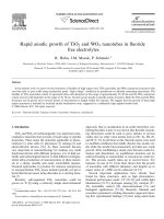
rapid anodic growth of tio2 and wo3 nanotubes in fluoride free electrolytes
Bạn đang xem bản rút gọn của tài liệu. Xem và tải ngay bản đầy đủ của tài liệu tại đây (871.1 KB, 6 trang )
Rapid anodic growth of TiO
2
and WO
3
nanotubes in fluoride
free electrolytes
R. Hahn, J.M. Macak, P. Schmuki
*
Department of Materials Science, WW4-LKO, University of Erlangen-Nuremberg, Martensstrasse 7, D-91058 Erlangen, Germany
Received 17 November 2006; received in revised form 28 November 2006; accepted 30 November 2006
Available online 5 January 2007
Abstract
In the present work we report on the formation of bundles of high aspect ratio TiO
2
nanotubes and WO
3
nanopores structures with
very thin tube or pore walls using anodization under ‘‘high voltage’’ conditions in perchlorate or chloride containing electrolytes. The
bundles of TiO
2
nanotubes consist of separated tubes with diameters in the range of approximately 20–40 nm and the WO
3
nanopores
consist of pores with diameters in the range of 30–50 nm. Growth occurs locally at specific surface locations. Both the TiO
2
and the WO
3
structures can be grown up to several dozens of micrometers in length within few minutes. We suggest that the growth of these high
aspect structures is initiated by localized anodic breakdown event, triggered by a sufficiently high applied anodic field.
Ó 2006 Elsevier B.V. All rights reserved.
Keywords: Titanium dioxide; Tungsten trioxide; Nanotubes; Nanopores; Anodization
1. Introduction
TiO
2
and WO
3
are technologically very important semi-
conductive materials that provide a broad range of specific
properties. These make the materials applicable in photo-
catalysis [1], solar cells [2], photolysis [3] , sensing [4], and
electrochromic devices [5,6]. As these materials become
very important in nanotechnology for making very small
functional devices with different purposes, it is of high sci-
entific and technological interest to find different strategies,
which allow production of nanostructures of these materi-
als in a cheap, tunable and easily controllable manner.
Classical approaches to produce for instance nanoporous
or nanoparticulate TiO
2
layers include typically sol–gel or
hydrothermal processes using alkoxides as a starting mate-
rial [7].
Recently, self-organized TiO
2
nanotubes could be
grown on Ti [8] using a relatively simple electrochemical
approach, that is, anodization in an acidic electrolyte con-
taining fluorides. Later, it was shown that fluoride contain-
ing electrolytes could be used to grow tubular or porous
oxides also on other valve metals such as Nb, Ta, Hf, Zr,
and W [9–13]. In all these works, fluoride anions were used
to establish conditions that mildly dissolve the anodic oxi-
des while the anodic bias permanently provides new oxide
growth. After establishing a steady state between oxide for-
mation and dissolution, an equilibrium situation can be
achieved leading to nanotubular or nanoporous oxide lay-
ers. This process usually takes up to several hours. For
instance, in case of Ti, it has been shown that the growth
of nanotubes with different diameters and lengths up to
aspect ratios of $2000 can be achieved [14–19].
Several important applications have already been
found for these structures, such as high photoelectro-
chemical performance under UV [20–22] and visible light
illumination [23–25], hydrogen sensing [26], catalysis [27–
29], wettability control [30], electrochromism [31],and
biological applications [32–34]. Recently, Masuda and
coworkers presented a striking alternative approach show-
ing first experimental findings [35] that using electrolytes
1388-2481/$ - see front matter Ó 2006 Elsevier B.V. All rights reserved.
doi:10.1016/j.elecom.2006.11.037
*
Corresponding author. Tel.: +49 9131 852 7575; fax: +49 9131 852
7582.
E-mail address: (P. Schmuki).
www.elsevier.com/locate/elecom
Electrochemistry Communications 9 (2007) 947–952
containing perchlorate anions and using a set of specific
anodization conditions, it is possible to form bundles of
high aspect ratio TiO
2
nanotubes on Ti under very rapid
growth conditions. These structures are intended to be
used in dye-senstitized solar cells. In the present work,
we investigate the anodization of Ti and W substrates
in aqueous electrolytes with perchlorates or chlorides
additions, to explore the general feasibility of this princi-
ple and to gain some insight into the growth mechanism
of this novel growth approach.
2. Experimental part
Titanium and tungsten foils (0.1 mm, 99.6% purity,
Advent Materials) were prior to electrochemical experi-
ments degreased by sonication in acetone, isopropanol
and metha nol, afterwards rinsed with deionized (DI) water
and finally dried in nitrogen stream. The samples were
pressed together with a Cu-plate contact against an O-ring
in an electrochemical cell (1 cm
2
exposed to the electrolyte)
and anodized at different potentials in the range of
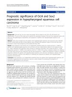
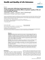
Fig. 1. SEM images of (a) TiO
2
nanotubes prepared in 0.1 M HClO
4
at 30 V for 60 s in the cross-sectional view; (b) WO
3
nanopores prepared in 0.1 M
HClO
4
at 50 V for 60 s in the cross-sectional view; (c) TiO
2
nanotubes prepared in 0.3 M NaCl solution (buffered pH 4) at 40 V for 60 s in the cross-
sectional view; (d) WO
3
nanopores prepared in 0.3 M NaCl (buffered pH 4) at 50 V for 60 s in the cross-sectional view.
948 R. Hahn et al. / Electrochemistry Communications 9 (2007) 947–952
10–100 V in aqueous electrolytes containing HClO
4
and
NaClO
4
(0.01; 0.05; 0.1, 1 M). Anodization was carried
out by stepping the potential to the desired value and hold-
ing it at the final value for a given time (typically several
minutes). For the electrochemical experiments, a high-volt-
age potentiostat Jaissle IM P 88 and a conventional three-
electrode configuration with a platinum gauze as a counter
electrode and the Haber–Luggin capillary with Ag/AgCl
(1 M KCl) as a reference electrode were used. All electro-
lytes were prepared from reagent grade chemicals. Some
experiments were conducted at lower temperatures using
a Lauda RM6 thermostat with a cooling coil, which was
directly immersed in the electrolyte solution. A scanning
electron microscope Hitachi FE-SEM S4800 and a trans-
mission electron microscope Phillips CM 30 T/STEM were
employed for the morphological and structural character-
ization of the formed layers. Energy dispersive X-ray ana-
lyser (EDX) fitted to the SEM chamber was used for
determining the composition.
3. Result s and discussion
After some preliminary anodization experiments it was
clear that using potential steps in perchlorate or chloride
containing electrolytes, passivity breakdown conditions
could be established – the latter being in line with extended
Fig. 1 (continued )
R. Hahn et al. / Electrochemistry Communications 9 (2007) 947–952 949
work on ‘‘pitting corrosion’’ on Ti, see e.g., Ref. [36]. The
result is that specific spots on the electrode surface become
activated and very high current densities are observed.
When stopping this process, after a few minutes, one can
see (by eye) several white spots on the sample surface.
Using a FE-SEM and zooming in on these locations, one
can clearly observe nanotubular morphologies as shown
in Fig. 1. Fig. 1a and b shows SEM images of bundles of
closely packed TiO
2
nanotubes prepared in ClO
À
4
and
Cl
À
solutions. The tubes have an average diameter of
40 nm, a length of 30 lm, and a wall thickness of about
10 nm. Fig. 1c and d shows SEM images of nanoporous
WO
3
prepared in ClO
À
4
and Cl
À
containing electrolytes.
In this case, bundles of WO
3
nanopore structures show
an average pore diameter of 40 nm, and a structure length
of 16 lm.
Based on our direct observations and as confirmed by a
time sequence of experiments, the tube growth in every case
starts randomly on certain points on the surface, and the
amount of these tubular bundles increases with anodiza-
tion time until the whole surface is covered. In order to
form these nanostructured materials, sufficiently ‘‘harsh’’
anodization conditions must be established to cause break-
down events during the experiments. Specifically the elec-
trolyte composition, temperature and applied potential
must be such that the anodized metals undergo localized
breakdown. For breakdown to occu r in the case of TiO
2
(or WO
3
) in chloride containing electrolytes, typically
potentials of several 10 V must be applied [37–39]. Further,
it is very impor tant how these potentials are applied, either
by sweeping or by stepping the voltage. This fact influences
the formed oxide layers in terms of its density, porosity,
and defects [40]. When we applied the potential by sweep-
ing (‘‘mild anodization’’) to relatively high potentials (up to
80 V) only the formation of compact TiO
2
and WO
3
layers
with thicknesses proportional to the app lied potentials
could be observed. However, when the potential is stepped,
a completely different situation occurs, i.e., breakdown
events take place (as a result of the higher applied field
strength) and as a side-effect, formation of the nanostruc-
tures takes place. This very different behaviour is demon-
strated in Fig. 2a. In one case, it shows the current–time
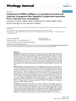
Fig. 2. (a) Current transients of Ti sample anodized in 0.05 M HClO
4
at 30 V final potential recorded after a potential step and a potential sweep (with
1 V/s); (b) current transients of W sample anodized in 0.1 M HClO
4
at 50 V final potential after a potential step and a potential sweep (1 V/s); (c) current
transients of Ti sample recorded after 20 V potential step in aqueous solutions containing different HClO
4
concentrations. Insets are typically SEM top
views of the surface acquired under these conditions.
950 R. Hahn et al. / Electrochemistry Communications 9 (2007) 947–952
dependence recorded for Ti sample anodized in 0.05 M
HClO
4
after applying the 30 V in one step and in the other
case, after sweeping the potential to 30 V with 1 V/s. It is
apparent that anodization occurs under very different cur-
rent flow (the currents in the case of step anodization are
more than 10 · higher) considering the localized nature
of the events. The local dissolution currents are anticipated
to be several decades higher (as expected for ‘‘pitting’’ cor-
rosion [36]).
For Ti as a substrate, the formation of TiO
2
nanotubes
in ClO
À
4
containing solution is possible over a broad range
of the experimental conditions. Bundles of nanotubes can
be observed between applied potentials of 15 and 60 V, in
the ClO
À
4
electrolyte with concentrations in the range
between 0.01 and 3 M. This rapid process leads to forma-
tion of flower-like bundles of nanotubes, with lengths of
3–50 lm within some minutes. Changes in the conditions
do not affect the geometry of the individual tubes – rather
they affect nucleation density and growth rate. The final
surface coverage and amo unt of tubular bundles seem to
be strongly dependent on the conditions used to induce
the initial localized breakdown. Applying a high potential
step leads to a higher number of initiation sites and thus
to a rapid growth and coverage of the surface with nanotu-
bular bundles. The same effect can be observed when using
W as the substrate material instead of Ti (Fig. 2b). In the
case of W, the formation of nanoporous WO
3
in ClO
À
4
solution typically requires higher applied potentials (by
steps), in the range between 50 and 80 V. Cooling the elec-
trolytes (down to 4 °C) for both cases led to formation of
similar nanostructures, but the growth rate could be
decreased and in general it allowed us to use higher poten-
tials, which in turn, increased the nucleation density and
thus led to more homogeneous and denser coverage of
the surfaces by the nanostructures. Fig. 2c presents the cur-
rent transients of Ti samples recorded after a potential step
to 20 V in HClO
4
solutions with different concentrations. It
is evident that with higher concentrations, higher currents
are recorded due to breakdown and nanotube formation.
For very low HClO
4
, stable and reproducible breakdown
conditions can hardly be establ ished, therefore no or only
a few locations are present on the sample surface where
successful nanotube growth was achieved. If the HClO
4
concentration is too high, the formed nanomaterial
appears much more disordered; rough and porous struc-
tures are formed instead of tubes. Therefore, not only ano-
dic potential steps are required, but also the optimized
concentration of the ions in the solutions as well.
In order to gain more insight in these structures, we
investigated them further by TEM and analyzed the com-
position by EDX. Fig. 3a shows a TEM image of the
TiO
2
bundles in detail and clearly demonstrates that these
bundles consist of nanotubes with tube diameters of
20–40 nm and a wall thickness of up to 20 nm. X-ray dif-
fraction measurements (XRD, not shown) revealed an
amorphous structure of the as-formed TiO
2
nanotubes.
Subsequent annealing at 450 °C for 3 h in air led to crystal-
lization to anatase TiO
2
, which is of significance for, e.g.,
photoelectrochemical applications [1,2,21]. XRD of WO
3
nanoporous layers also revealed their amorphous struc ture.
Fig. 3b shows examples of EDX spectra of the nanotubular
TiO
2
and the nanoporous WO
3
structures. As can be seen
for the Ti sample, there are four elements detected (Ti, O,
Cl, Al). By evaluating these spectra, we found out that the
approximate atomic ratio of Ti to O is 1 : 2 (matching TiO
2
)
and the Cl content in all samples is lower than 3% (from
the traces of the electrolyte remaining in the tubes). The
small Al peak stems from the screw of the sample holder
Fig. 3. (a) TEM image of TiO
2
nanotubes; (b) EDX spectra of a
nanotubular TiO
2
and a nanoporous WO
3
layer.
R. Hahn et al. / Electrochemistry Communications 9 (2007) 947–952 951
used to anchor the sample. In the case of W, the ratio
between W and O is 1 :3 (matching WO
3
), but in this case,
no chlorine peaks are detected. To summarize, the best and
the most dense coverage can be achieved by using cooling ,
medium concentrations of perchlorates (0.1–0.5 M) and
applying rather higher voltages (>40 V for Ti and >50 V
for W) in one or just a few steps and stabilizing the pH with
buffers. In contrast to well-ordered, self-organized nanotu-
bular arrays grown in electrolytes containing fluorides [14–
20], the approach presented here is considerably more sto-
chastic in nature. As for other localized corrosion processes
initiation takes place at the ‘‘weakest’’ sites of an anodized
surface. This leads to a less controlled growth and inhomo-
geneous distributions not only in surface coverage but also
in tube length at different locations on the surface. How-
ever, as discus sed above, several measures can make the
layers more uniform. Key to achieve homogeneous and
dense packaging is triggering a higher number of initiation
sites by a higher voltage. Other possibilities may be the
introduction of predefined initiation sites or using pH-buf-
fers to smoothen the pH-profile over the surface. At pres-
ent, this breakdown approach does not seem to be
limited to ClO
À
4
or Cl
À
ions, but may be achieved by any
ion that supports localized breakdown on anodized Ti or
W surfaces.
4. Conclusions
The results of the present work demonstrate that bun-
dles of high aspect ratio TiO
2
nanotubes and WO
3
nanop-
ores can successfully be formed using a fluoride free
approach – the anodization in perchlorate or chloride con-
taining electrolytes. The results clearly indicate that this
method is capable of producing high aspect ratio nano-
structures (several dozens of micrometers in length vs. sev-
eral dozens of nanometers in diameter) in a very short time
(some minutes). As the formation is induced by localized
anodic breakdown and its progression, the grow th process
is somewhat arbitrary. However, it is possible to tailor the
conditions to achieve relatively homogeneous and dense-
packed nano-bundles consisting of nanotubes or nanop-
ores on the metallic surface.
Acknowledgements
The authors acknowledge DFG for financial support.
Hans Rollig and Martin Kolacyak are acknowledged for
valuable technical help.
References
[1] A. Fujishima, K. Honda, Nature 238 (1972) 37.
[2] B. O’Regan, M. Gra
¨
tzel, Nature 353 (1991) 737.
[3] M.A. Butler, R.D. Nashby, R.K. Quinn, Solid State Commun. 19
(1976) 1011.
[4] O.K. Varghese, C.A. Grimes, J. Nanosci. Nanotech. 3 (2003) 277.
[5] H. Tokudome, M. Miyauchi, Angew. Chem., Int. Ed. 44 (2005)
1974.
[6] A.E. Aliev, H.W. Shin, Solid State Ion. 154 (2002) 425.
[7] M. Gotic, M. Ivanda, A. Sekulic, S. Music, S. Popovic, A. Turkovic,
K. Furic, Mater. Lett. 28 (1996) 225.
[8] V. Zwilling, E. Darque-Ceretti, A. Boutry-Forveille, Electrochim.
Acta 45 (1999) 921.
[9] H. Tsuchiya, P. Schmuki, Electrochem. Commun. 6 (2004) 1131.
[10] H. Tsuchiya, P. Schmuki, Electrochem. Commun. 7 (2005) 49.
[11] I. Sieber, B. Kannan, P. Schmuki, Electrochem. Solid State 8 (2005)
J10.
[12] I. Sieber, H. Hildebrand, A. Friedrich, P. Schmuki, Electrochem.
Commun. 7 (2005) 97.
[13] H. Tsuchiya, J.M. Macak, I. Sieber, L. Taveira, A. Ghicov, K.
Sirotna, P. Schmuki, Electrochem. Commun. 7 (2005) 295.
[14] J.M. Macak, K. Sirotna, P. Schmuki, Electrochim. Acta 50 (2005)
3679.
[15] J.M. Macak, H. Tsuchiya, P. Schmuki, Angew. Chem., Int. Ed. 44
(2005) 2100.
[16] L. Taveira, J.M. Macak, H. Tsuchiya, L.F.P. Dick, P. Schmuki, J.
Electrochem. Soc. 152 (2005) B405.
[17] S. Albu, A. Ghicov, J.M. Macak, P. Schmuki, Phys. Status Solidi.
(RRL) 1 (2007) R65.
[18] H. Tsuchiya, J.M. Macak, L. Taveira, E. Balaur, A. Ghicov, K.
Sirotna, P. Schmuki, Electrochem. Commun. 7 (2005) 576.
[19] S. Bauer, S. Kleber, P. Schmuki, Electrochem. Commun. 8 (2006)
1321.
[20] K.S. Raja, M. Misra, K. Paramguru, Electrochim. Acta 51 (2005)
154.
[21] R. Beranek, H. Tsuchiya, T. Sugishima, J.M. Macak, L. Taveira, S.
Fujimoto, H. Kisch, P. Schmuki, Appl. Phys. Lett. 87 (2005) 243114.
[22] S. Berger, H.Tsuchiya.A. Ghicov, P. Schmuki, Appl. Phys. Lett. 88
(2006) 203119.
[23] J.M. Macak, H. Tsuchiya, A. Ghicov, P. Schmuki, Electrochem.
Commun. 7 (2005) 1138.
[24] A. Ghicov, J.M. Macak, H. Tsuchiya, J. Kunze, V.Heaublein.L. Frey,
P. Schmuki, Nanoletters 6 (2006) 1080.
[25] J.M. Macak, A. Ghicov, R. Hahn, H. Tsuchiya, P. Schmuki, J.
Mater. Res. 21 (2006) 2824.
[26] O.K. Varghese, D. Gong, K.G. Ong, C.A. Grimes, Sensors Actuator.
B93 (2003) 338.
[27] J.M. Macak, P.J. Barczuk, H. Tsuchiya, M.Z. Nowakowska, A.
Ghicov, M. Chojak, S. Bauer, S. Virtanen, P.J. Kulesza, P. Schmuki,
Electrochem. Commun. 7 (2005) 1417.
[28] P.J. Barczuk, H. Tsuchiya, J.M. Macak, P. Schmuki, D. Szymanska,
O. Makowski, K. Miecznikowski, P.J. Kulesza, Electrochem. Solid
State 9 (2006) E13.
[29] Y. Lai, L. Sun, Y. Chen, H. Zhuang, Ch. Lin, J.W. Chin, J.
Electrochem. Soc. 153 (2006) D123.
[30] E. Balaur, J.M. Macak, H. Tsuchiya, P. Schmuki, J. Mater. Chem. 15
(2005) 4488.
[31] A. Ghicov, H. Tsuchiya, R. Hahn, J.M. Macak, A.G. Munoz,
Electrochem. Commun. 8 (2006) 528.
[32] H. Tsuchiya, J.M. Macak, L. Muller, J. Kunze, F. Muller, S.P. Greil,
S. Virtanen, P. Schmuki, J. Biomed. Mater. Res. 77A (2006) 534.
[33] J.M. Macak, H. Tsuchiya, L. Taveira, A. Ghicov, P. Schmuki, J.
Biomed. Mater. Res. 75A (2005) 928.
[34] S. Oh, Ch. Daraio, L.H. Chen, T.R. Pisanic, R.R. Fin
˜
ones, S. Jim, J.
Biomed. Mater. Res. 78A (2006) 97.
[35] K. Nakayama, T. Kubo, A. Tsubokuira, Y. Nishikitani, H. Masuda,
Abstract # 819, in: 208th ECS Meeting, Hawai, 2005.
[36] S. Szklarska-Smialowska, Pitting Corrosion of Metals, NACE,
Houston, 1986.
[37] C.K. Dyer, J.S.L. Leach, J. Electrochem. Soc. 125 (1978) 1032.
[38] N. Sato, Electrochim. Acta 16 (1971) 1683.
[39] J.W. Schultze, M.M. Lohrengel, Electrochim. Acta 45 (2000)
2499.
[40] T. Ohtsuka, T. Otsuki, Corros. Sci. 40 (1998) 951.
952 R. Hahn et al. / Electrochemistry Communications 9 (2007) 947–952