- Trang chủ >>
- Khoa Học Tự Nhiên >>
- Vật lý
synthesis of hematite (r-fe2o3) nanorods diameter-size and shape effects on their
Bạn đang xem bản rút gọn của tài liệu. Xem và tải ngay bản đầy đủ của tài liệu tại đây (554.62 KB, 7 trang )
Synthesis of Hematite (r-Fe
2
O
3
) Nanorods: Diameter-Size and Shape Effects on Their
Applications in Magnetism, Lithium Ion Battery, and Gas Sensors
Changzheng Wu, Ping Yin, Xi Zhu, Chuanzi OuYang, and Yi Xie*
Department of Nano-materials and Nano-chemistry, Hefei National Laboratory for Physical Sciences at
Microscale, UniVersity of Science & Technology of China, Hefei, Anhui 230026, China
ReceiVed: June 1, 2006; In Final Form: July 16, 2006
We demonstrated in this paper the shape-controlled synthesis of hematite (R-Fe
2
O
3
) nanostructures with a
gradient in the diameters (from less than 20 nm to larger than 300 nm) and surface areas (from 5.9 to 52.3
m
2
/g) through an improved synthetic strategy by adopting a high concentration of inorganic salts and high
temperature in the synthesis systems to influence the final products of hematite nanostructures. The benefits
of the present work also stem from the first report on the <20-nm-diameter and porous hematite nanorods,
as well as a new facile strategy to the less-than-20-nm nanorods, because the less-than-20-nm diameter size
meets the vital size domain for magnetization properties in hematite. Note that the porous and nonporous
hematite one-dimensional nanostructures with diameter gradients give us the first opportunity to investigate
the Morin temperature evolution of nanorod diameter and porosity. Evidently, the magnetic properties for
nanorods exhibit differences compared with those for the spherical particle counterparts. Hematite nanorods
are strongly dependent on their diameter size and porosity, where the magnetization is not sensitive to the
size evolution from submicron particles to the 60-90 nm nanorods, while the magnetic properties change
significantly in the case of <20 nm. In other words, for the magnetic properties of nanorods, in a comparable
size range, the porous existence could also influence the magnetic behavior. Moreover, applications in
formaldehyde (HCHO) gas sensors and lithium batteries for the hematite nanostructures with the diameter/
surface area gradient reveal that the performance of electrochemical and gas-sensor properties strongly depends
on the diameter size and Brunauer-Emmett-Teller (BET) surface areas, which is consistent with the crystalline
point of view. Thus, this work not only provides the first example of the fabrication of hematite nanostructure
sensors for detecting HCHO gas, but also reveals that the surface area or diameter size of hematite nanorods
can also influence the lithium intercalation performances. These results give us a guideline for the study of
the size-dependent properties for functional materials as well as further applications for magnetic materials,
lithium-ion batteries, and gas sensors.
1. Introduction
Developing new methods for the preparation of nanomaterials
as well as the modification of their size, morphology, and
porosity, has been intensively pursued not only for their
fundamental scientific interest but also for many technological
applications. Nanoparticles (zero-dimensional (0-D)) and nano-
wires/nanorods (one-dimensional (1-D)) with controlled size and
shape are of key importance because their electrical, optical,
and magnetic properties strongly depend on their size and
shape.
1
Hematite (R-Fe
2
O
3
), the most stable iron oxide, with
n-type semiconducting properties under ambient conditions, is
of scientific and technological importance because of its usage
in catalysts, pigments, magnetic materials, gas sensors, and
lithium-ion batteries.
2
Its size and shape effect on corresponding
properties has attracted much attention. For example, the Morin
transition temperature (T
M
)ofR-Fe
2
O
3
nanoparticles (0-D)
decreases with decreasing spherical particle size according to a
1/d dependence.
3
Additionally, 1-D R-Fe
2
O
3
nanostructures,
such as nanorods,
4
nanowires,
5
nanobelts,
6
and nanotubes
7
have
also been synthesized and used for investigating their peculiar
properties. For example, Woo et al. synthesized R-Fe
2
O
3
nanorods by a sol-gel mediated reaction of ubiquitous Fe
3+
ions in reverse micelles.
8
Zhang et al. managed to grow R-Fe
2
O
3
nanowires out of the oxidized surface of iron substrates.
9
Recently, R-Fe
2
O
3
hollow nanowires with outer diameters of
ca. 50 nm have been synthesized through a vacuum-pyrolysis
route from β-FeOOH nanowires.
10
Nevertheless, it still remains
a challenge to develop simple and versatile approaches to
synthesize 1-D nanostructures of R-Fe
2
O
3
with slimmer diam-
eters, which will then facilitate our understanding of the shape-
and size-dependent properties of R-Fe
2
O
3
.
Since the Morin temperature of R-Fe
2
O
3
spherical particles
was found to be strongly dependent on particle size and tends
to disappear (<5 K) below a diameter of 8-20 nm,
11
their
counterpart nanorods/nanowires with a diameter of <20 nm are
then significantly necessary for further understanding of the
magnetic properties. Currently, because of limited studies on
R-Fe
2
O
3
nanorods/nanowires with a diameter of <20 nm and
because their <20 nm and porous nanorods have not been
obtained so far, their subsequent applications in magnetization
fields and investigations on the size-dependent properties of iron
oxides are significantly delayed. Herein, we demonstrate the
synthesis of R-Fe
2
O
3
nanorods with a gradient in the surface
* Corresponding author. Address: Department of Nano-materials and
Nano-chemistry. Hefei National Laboratory for Physical Sciences at
Microscale, University of Science and Technology of China, Hefei, Anhui
230026, P. R. China. Tel: 86-551-3603987. Fax: 86-551-3603987. E-
mail:
17806 J. Phys. Chem. B 2006, 110, 17806-17812
10.1021/jp0633906 CCC: $33.50 © 2006 American Chemical Society
Published on Web 08/19/2006
areas and diameter sizes via an improved strategy: first, by
adopting high-concentration salts and high temperature, the as-
produced R-orβ-FeOOH nanorods are slimmer than usual in
our synthetic system. Then with the influence of inorganic salt
ions, the samples pyrolyze at a slower rate, and then the
corresponding well-defined hematite nanostructures can be
achieved. Note that the hematite crystal structure is a rhombo-
hedrally centered hexagonal structure of the corundum type with
a closed-packed lattice; there are no tunnels or interlayer spacing
for accommodating the inorganic ions any more, as is the case
for R-FeOOH or β-FeOOH crystal structures (see Supporting
Information). Therefore, the inorganic ions can be easily
removed after calcining, and the pure hematite (R-Fe
2
O
3
) could
be obtained after rinsing with water. Here, the hematite
morphology with different sizes and shapes could be well
controlled by simply choosing different kinds of inorganic salts.
This work presents not only a new strategy to produce R-Fe
2
O
3
nanorods with diameters of <20 nm, but also the first report
on the synthesis of porous R-Fe
2
O
3
nanorods with diameters of
<20 nm. Evidently, the magnetic properties were strongly
dependent on the size of their diameter and the porosity in the
present work, while the lithium intercalation and HCHO gas
sensor properties were significantly dependent on the surface
area. Therefore, the present work provides not only the first
example of investigating the magnetic property evolution of
nanorods/nanowire diameters and porosity, but also the first
example of the fabrication of hematite nanostructure sensors
for detecting HCHO gas.
2. Experimental Section
To prepare FeOOH nanostructure precursors, 50 mL of 0.06
M iron chloride (FeCl
3
) aqueous solution, with/without the
addition of 0.300 mol of inorganic salts (NH
4
Cl, KCl, and Na
2
-
SO
4
) was put in a conical flask and stirred with a magnetic
stirrer for 30 min. The homogeneous solution was then
transferred into a 60 mL Teflon-lined stainless steel autoclave,
sealed, and then heated to 120 °C. After the autoclaves were
maintained at 120 °C for 12 h, the resulting yellow product
was centrifuged, rinsed with distilled water, and finally dried
at 40 °C in a vacuum. The obtained yellow solid products were
collected for the following experiments and characterization.
To prepare hematite nanostructures, the as-prepared FeOOH
nanostructures were heated to 520 °C with a ramping rate of
10 °C min
-1
and then maintained at 520 °Cfor8h.The
decomposition was performed in air, and the synthetic conditions
are summarized in Table 1, where the as-obtained R-Fe
2
O
3
nanostructures have been named S1, S2, S3, and S4. The as-
collected R-Fe
2
O
3
products were rinsed with distilled water and
finally dried at 40 °C in a vacuum.
The samples of as-prepared FeOOH and R-Fe
2
O
3
nanostruc-
tures were characterized by X-ray powder diffraction (XRD)
with a Philips X’Pert Pro Super diffractometer with Cu KR
radiation (λ ) 1.54178 Å). The transmission electron micros-
copy (TEM) images for both FeOOH and R-Fe
2
O
3
were
obtained on a Hitachi Model H-800 instrument with a tungsten
filament at an accelerating voltage of 200 kV. The selected-
area electron diffraction patterns and high-resolution transmis-
sion electron microscopy (HRTEM) images were obtained on
a JEOL-2010 TEM at an acceleration voltage of 200 kV. The
porosity and adsorption performance of R-Fe
2
O
3
were deter-
mined via a Micromeritics ASAP-2000 nitrogen adsorption
apparatus. The magnetic properties of R-Fe
2
O
3
were measured
using a vibrating sample magnetometer and superconducting
quantum interference device. The performance of the R-Fe
2
O
3
as a cathode was evaluated using a Teflon cell with a lithium
metal anode. The cathode was a mixture of β-FeOOH/acetylene
black/poly(vinylidene fluoride) with a weight ratio of 85/10/5.
The electrolyte was 1 M LiPF
6
in a 1:1 mixture of ethylene
carbonate/diethyl carbonate, and the separator was Celgard 2500.
The cell was assembled in a glovebox filled with highly pure
argon gas (O
2
and H
2
O levels < 5 ppm). A galvanostatic charge/
discharge experiment was performed between 3.0 and 0.5 V at
a current density of 0.2 mA cm
-2
.
Gas sensing measurements were performed with a WS-30A
system (Weisheng Instruments Co., Zhengzhou, China), and the
system integral error for the WS-30A system was less than
(1%. The sensors of the as-prepared samples were fabricated
on ceramic tubes with the connection of gold electrodes that
were connected by four platinum wires. Here, the sensor
structure and the testing principle were similar to that for
previous reports.
12
In this case, the mixture of the as-prepared
hematite nanomaterials and ethanol was coated as a thin film
spanning across the two Au electrodes. After drying at 150 °C
for2hinairtoimprove stability, the electrical contact was
made through connecting the four platinum wires with the
instrument base by silver paste. Before analysis, the sensors-
settled chamber was kept under a continuous flow of fresh air
for 30 min. During the measurement, the sensors were hosted
in a closed plastic tube equipped with appropriate inlets and
outlets for gas flow. A given amount of formaldehyde (HCHO)
was injected into the chamber by a microinjector. The sensitivity
could be measured when the detecting gas was mixed with air
homogeneously. Here, the response magnitude, S, is defined as
R
s(air)
/R
s(gas)
, where R
s(air)
and R
s(gas)
are the resistance of the
sensor in clean air and in detected gas, respectively.
3. Results and Discussion
3.1. Morphology, Characterization, and Formation Mech-
anism of the As-Obtained Hematite Nanostructures. The
hematite nanostructures could be originated from the well-
controlled FeOOH nanostructure precursors (see Supporting
Information), and all the synthetic conditions are summarized
in Table 1. Furthermore, the phase and morphology information
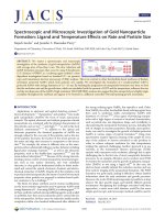
for the as-obtained products are revealed by Figure 1, where
panels c, f, i, and m are the corresponding XRD patterns for
panels a-b, d-e, g-h, and j-l, respectively. All the XRD
patterns in Figure 1 show characteristics of pure hexagonal
R-Fe
2
O
3
(JCPDS card 33-664, a ) 5.035 Å and c ) 13.74 Å).
No characteristic peak was observed for other impurities such
as β-FeOOH, Fe
3
O
4
, γ-Fe
2
O
3
, and other inorganic ions. As
TABLE 1: Synthetic Conditions for Different r-Fe2O3 Nanostructures.
R-Fe
2
O
3
sample morphologies
average
diameter (nm)
reaction condition
for FeOOH precursors
S1 submicron particles 300-500 direct hydrolysis systems
S2 nanorods with porosity nanorods: 60-90
porosity: 20-50
FeCl
3
-KCl systems
S3 nanorods 5-16 FeCl
3
-Na
2
SO
4
systems
S4 nanorods with porosity nanorods: 5-19
porosity: 2-16
FeCl
3
-NH
4
Cl systems
Synthesis of Hematite (R-Fe
2
O
3
) Nanorods J. Phys. Chem. B, Vol. 110, No. 36, 2006 17807
is shown in Figure 1a,b, the appearance of S1 is the
hematite submicrometer particles with the diameter range of
300-500 nm, and no hollow structures were found even from
the amplified TEM image for the direct hydrolysis system. The
calcined products (S2) from the FeCl
3
-KCl system have the
regular pores (20-50 nm) distributed along the hematite
nanorods with a diameter-size range of 60-90 nm, as shown
in Figure 1d,e. The calcining products (S3) obtained in the
FeCl
3
-Na
2
SO
4
system were mostly solid nanorods with diam-
eters of <15 nm, as shown in Figure 1g. The HRTEM image
of a single-crystalline solid nanorod in Figure 1h shows a clear
interplanar distance of 0.25 nm, matching well with the d
110
spacing of pure hexagonal hematite. Figure 1j displays that
heating the products prepared in the FeCl
3
-NH
4
Cl system
yielded the nanoporous crystalline R-Fe
2
O
3
nanostructures (S4)
without altering the morphology of the 1-D and even the
nanorod bundles, and many holes with sizes of 8-30 nm form
in the nanorods (Figure 1k). The TEM image with higher
magnification shows that the porous appearance can be clearly
observed in all the visible nanorods, with uniform pores of <10
Figure 1. Representative TEM and HRTEM images of the as-obtained R-Fe
2
O
3
nanostructures with different diameter sizes for S1 (a-b), S2
(d-e), S3 (g-h), and S4 (j-l). The corresponding XRD patterns for the samples of S1, S2, S3, and S4 are shown in panels c, f, i, and m, respectively.
(n) The magnified (110) peaks for these four samples, where the (110) peak becomes narrower in the sequence of S4-S1, revealing the size
evolution.
17808 J. Phys. Chem. B, Vol. 110, No. 36, 2006 Wu et al.
nm (Figure 1l). Evidently, the above TEM images were
consistent with the analysis of the magnified (110) peak, as
shown in Figure 1n, where the (110) peak becomes narrower
in the sequence of S4-S1, and the sharper peaks for S1 indicate
its good crystallinity and greater grain size than the other three
products (S2-S4) whose precursors grew under the control. On
the basis of the combination analysis of TEM images and XRD
patterns, the as-obtained R-Fe
2
O
3
nanostructures possess diameter-
sized gradients in the sequence from S4 to S1 with increasing
sizes.
As described above, the systems with the addition of inorganic
salts retained the morphology of the FeOOH precursors, and
regular nanopores formed along the nanorods, while the direct
hydrolysis system produced only particles under air conditions.
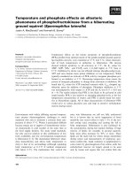
The phenomenon can be explained by the difference in
thermalstability behavior based on DrTGA, as shown in Figure
2. From DrTGA curves, one can see that there is a broad
exothermal peak with a coexistence of feeble shoulder peaks
in the temperature range of 200-400 °C for each of S2-S4,
showing that their weight loss is much more lagged. The
intensity of the exothermal peak for S1 (Figure 2a) without salt
addition in the temperature range of 200-400 °C is evidently
stronger than the corresponding peaks for the other three samples
with the addition of high-concentration salt ions, indicating that
the weight loss is much quicker. Compared with the direct
hydrolysis systems (S1), the final products of FeOOH in the
other three systems will possess more ions to bind with the
tunnel structures or the surface sites of R-orβ-FeOOH crystal,
and the total amounts of the residual ions that can be removed
in the calcination process
13
are too small to be reflected by the
XRD pattern. Thus, the small amount of residual inorganic salt
ions seems to be responsible for the formation of hollow
structures in our synthetic conditions.
In fact, the addition of inorganic salt ions enables the samples
to pyrolyze at a slower rate. As for the products of β-FeOOH
with the absence of adequate ions in the direct hydrolysis
systems, this high-rate pyrolysis process will produce too much
energy in a short time to be effectively released from the
systems, as indicated by a stronger peak in the curve. Most of
the energy was adsorbed in the systems, resulting in the collapse
of the nanorods to form larger aggregated particles, as shown
in Figure 1a,b, whereas, for the inorganic salt systems, the
existence of salt ions binding with the FeOOH precursors
impedes the samples to pyrolyze at the higher rates, and the
as-produced energy could have enough time to be effectively
released from the systems, and the final products of R-Fe
2
O
3
obtained possess the regular pores and the morphology remi-
niscent of their precursors (β-FeOOH). In a word, the pyrolysis
rates of β-FeOOH seem to be a significantly influencing
parameter for the formation of porous R-Fe
2
O
3
and reminiscent
of the orientation-ordered nanostructures for R-Fe
2
O
3
in air
conditions based on the combined analysis of DrTGA and TEM
results.
Additionally, it is interesting that when the precursors are
prepared in high-concentration Cl
-
ions, the calcined products
have the appearance of porosity (S2 and S4), while in high-
concentration SO
4
2-
, S3 only has the solid appearance. These
results indicate that the existence of large amounts of Cl
-
ions
held in the tunnels in β-FeOOH might favor the appearance of
porosity in the calcined products such as S2 and S4. However,
the high-concentration large anions such as SO
4
2-
, which existed
in the surface sites,
14
might favor the formation of a solid
morphology for S3.
3.2. BET Surface Areas of r-Fe
2
O
3
Nanostructures. The
Brunauer-Emmett-Teller (BET) surface areas of S1 and S2
were found to be 5.9 and 15.8 m
2
/g, respectively, by calculating
from the results of N
2
adsorption. The BET values of S3 and
S4 show relatively higher surface areas of 32.5 and 52.3 m
2
/g,
respectively. Considering the factors that affect specific surface
area, we can conclude that, in a comparable size range, it is the
pores that increase specific surface area, according to the
comparison between S3 and S4, whereas, when there is a wide
size discrepancy, it is the size that determines the specific surface
area, according to the comparison between S2 and S3. It is worth
noting that the as-obtained R-Fe
2
O
3
nanostructures with the
gradient in BET surface area and diameter size, provide a fine
example to study the size-dependent properties of magnetization,
lithium batteries, and gas sensors.
3.3. Magnetic Properties for r-Fe
2
O
3
Nanostructures.
Owing to their gradient in the BET surface area and the diameter
size, the magnetic behavior of as-obtained R-Fe
2
O
3
nanostruc-
tures, which is of importance for practical applications, was
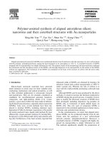
investigated for samples S1-S4. Figure 3 shows the curves for
the temperature dependence of zero-field-cooled (ZFC) and
field-cooled (FC) magnetizations from 4 to 300 K, under an
applied field of 500 Oe. The insets are the corresponding
differential ZFC curves.
As for the submicron solid particle sample S1, the FC and
ZFC magnetization curves overlap in the entire concerned
temperature range, as shown in Figure 3a, displaying the
characteristic behavior for R-Fe
2
O
3
with a Morin transition
temperature (T
M
) of 255 K, which is determined by the sharp
peak in the differential ZFC curve (inset in Figure 3a). Normally,
bulk hematite has a Morin transition from the low-temperature
antiferromagnetic phase to a weakly ferromagnetic phase at 263
K.
15
Here, the T
M
value for the submicron R-Fe
2
O
3
solid
particles is approaching that for bulk hematite. As for the sample
with 60-90 nm nanorods with porosities of 20-50 nm (S2),
as shown in Figure 3b, the characteristics of the ZFC and FC
magnetization curves show the same trend as those of S1, except
that these two curves slightly split in the temperature ranges of
4-100 and 260-300 K. Notably, the Morin transition temper-
ature of S2 remains 255 K, showing no change compared to
that of S1, which indicates that the magnetization is not sensitive
to the size evolution from submicron particles to the 60-90
nm nanorods. As for the 5-16 nm nanorods (S3), as shown in
Figure 2. DrTGA curves for the samples of the FeOOH precursors
obtained by the direct hydrolysis system (a), the FeCl
3
-KCl system
(b), the FeCl
3
-Na
2
SO
4
system (c), and the FeCl-NH
4
Cl system (d) at
heating rate of 10 °C min
-1
, from which the calcining influence
parameters for the formation of S1, S2, S3, and S4 could be discussed,
respectively. The relation between these system and the final products
of S1, S2, S3, and S4 mentioned in this work can be seen in Table 1.
Synthesis of Hematite (R-Fe
2
O
3
) Nanorods J. Phys. Chem. B, Vol. 110, No. 36, 2006 17809
Figure 3c, the FC and ZFC magnetization curves split signifi-
cantly; the FC magnetization rises significantly, while the ZFC
curve decreases slowly. The split between the FC and ZFC
curves reflects the existence of a large size distribution of
magnetic units resulting from the decrease in effective size,
whose moments block progressively with decreasing tempera-
ture.
16
Additionally, the Morin transition temperature for S3 (235
K) is lower than that for S1 and S2, which may be related to
the decrease in diameters for 1-D nanohematite, agreeing with
the theory that T
M
decreases with decreasing particle size. Since
the temperature of the overlap point is much higher than 100
K, the character of this curve should stem from a pilling center
effect, rather than spin glass freezing.
17
As for the sample with
5-19 nm nanorods with porosities of 2-16 nm (S4) in Figure
3d, the FC and ZFC magnetization curves split significantly,
and the Morin transition disappears in the concerned temperature
range of 4-300 K, indicating that the porous nanorods with
diameters less than 20 nm exhibit no Morin transition.
In summary, first, although our nanorods are grown prefer-
entially along (110) as single crystalline, the wire diameter
greatly restrains the maximal volume of the domain. Evidently,
T
M
decreased to 235 K when the diameters are less than 20 nm
for S3, while it seems to be insensitive to the size effect in the
case of diameters larger than 60 nm (S1 and S2). Second, the
experimental results show that the decreasing diameter of
nanorods could lead to the split in the ZC and ZFC magnetiza-
tion curves, which may result from the decrease in effective
size, whose moments block progressively with decreasing
temperature. Third, the porosity could also influence the
magnetic behavior in a comparable size range. For example,
for the case of S3 and S4, the porous product of S4 exhibits
no Morin transition in the concerned temperature range of
4-300 K.
3.4 r-Fe
2
O
3
Nanostructures in a Lithium-Ion Battery. It
is found that the lithium intercalation performance is related to
the intrinsic crystal structure, where the lithium ions can
intercalate into the interlayer, the tunnels, and the holes in the
crystal structure.
18
As for the hematite crystal structure, each
Fe atom is surrounded by six O atoms, whereas each O atom is
bound to four Fe atoms in a typical hematite crystal unit. A
hematite crystal has a rhombohedrally centered hexagonal
structure of the corundum type with a closed-packed lattice in
which two-thirds of the octahedral sites are occupied by Fe
3+
ions (see Supporting Information). As seen from the hematite
structure along [001], [100], and [110], there are no interlayer
spacings and tunnels through the crystal structure (See Sup-
porting Information). Upon careful observation of the hematite
surface structure, the holes could be observed in the first
octahedral layer projected along [001] and [100]; however, the
tunnels could not be seen as the layer number was increased,
as shown in Figure 4. That is to say, holes existed in the surface
hematite crystal, which allowed foreign atoms or molecules to
be introduced, for example, Li
+
ions. When the introduction of
lithium ions to the holes in the hematite surface is concerned,
it gives us the impression that the lithium intercalation perfor-
mance will improve by increasing the surface area or the
porosity of the hematite crystals. Therefore, the synthesis of
hematite nanocrystals with higher surface area or porosity
structures is much needed because of the intercalation capacities
and affinities for Li
+
to the more exposed holes in the hematite
Figure 3. Temperature dependence of ZFC and FC magnetization for an applied field of 500 Oe for S1 (a), S2 (b), S3 (c), and S4 (d). Insets are
their corresponding differential ZFC curves.
17810 J. Phys. Chem. B, Vol. 110, No. 36, 2006 Wu et al.
surface with higher surface area, which could then shorten the
diffusion length of lithium ions.
19
Evidently, the electrochemical performance of lithium ions
strongly depends on the diameter size and BET surface areas,
which agrees with the above considerations. As mentioned
above, the sample possesses a surface area with the sequence
of S4 > S3 > S2 > S1. The electrochemical performance of
the as-prepared hematite R-Fe
2
O
3
samples of S1-S4 in the cell
configuration of Li/R-Fe
2
O
3
was evaluated. Figure 5a shows
the comparison discharge curves for the concerned four samples
of S1-S4 on the first cycle with a cutoff voltage of 0.6 V at a
current density of 0.2 mA cm
-2
, which is similar to that of the
R-Fe
2
O
3
particles.
20
The S4 electrode exhibited a high discharge
capacity of 1151 mAh/g, corresponding to 6.8 Li per R-Fe
2
O
3
,
while the S3, S2, and S1 electrodes exhibited 1088, 981, and
894 mAh/g, corresponding to 6.5, 5.8, and 5.3 Li per R-Fe
2
O
3
,
respectively. According to the results presented above, it is
evident that the electrochemical properties of the first discharge
capacity possess the sequence of S4 > S3 > S2 > S1, which
is consistent with that of the surface areas for the as-obtained
R-Fe
2
O
3
nanostructures in this case.
3.5. The r-Fe
2
O
3
Nanostructures in Formaldehyde (HCHO)
Gas Sensors. As a toxic chemical component to our health,
formaldehyde (HCHO) widely exists in building materials and
in the combustion gas of organic materials. Thus, finding a way
to fabricate effective sensors for detecting the existence of
HCHO is much needed. R-Fe
2
O
3
, an n-type semiconductor with
an electrical conductivity highly sensitive to gaseous environ-
ments, has been used as a sensor for ethanol and H
2
.
21
Inspired
by this, we suspected that the as-obtained R-Fe
2
O
3
with different
BET surface areas should also be useful for the fabrication of
the HCHO sensors. From the crystalline point of view, there
are no interlayer spacings and tunnels through the crystal
structure, revealing that increasing the surface area could then
produce more activity sites for the HCHO sensors. The gas-
sensing characteristics of the as-obtained products from S1 to
S4 in response to HCHO are shown in Figure 6, in which the
curves are the plot of the gas sensitivity versus HCHO
concentration. The gas sensitivity, S
g
, is defined as R
air
/R
gas
,
where R
air
and R
gas
are the electrical resistances for sensors in
air and in gas.
22
Although the sensitivity of all the Fe
2
O
3
Figure 4. Schematic hematite structure projected along either [001]
(a) or [100] (b), where holes can be observed in the first octahedral
layer. No tunnels can be found as the layer number is increased.
Figure 5. First charge-discharge curves of hematite (R-Fe
2
O
3
) samples
(S1-S4) at a current density of 0.2 mA cm
-2
.
Figure 6. Room-temperature sensor sensitivity to formaldehyde
(HCHO) of the as-prepared hematite (R-Fe
2
O
3
) nanostructures for S1
(a), S2 (b), S3 (c), and S4 (d).
Synthesis of Hematite (R-Fe
2
O
3
) Nanorods J. Phys. Chem. B, Vol. 110, No. 36, 2006 17811
nanostructures (S1-S4) gradually increases with an increase
in HCHO gas concentration, as indicated in Figure 6, it can be
seen that the sensitivity of the as-obtained Fe
2
O
3
nanostructures
follows the sequence S4 > S3 > S2 > S1 under a given HCHO
concentration and testing temperature. Notably, this sensitivity
sequence is consistent with that for the BET surface area,
indicating the sensitivity for the nanostructures is coherent with
its corresponding surface area. These results verify the generally
accepted opinion that, for R-Fe
2
O
3
-based sensors, the change
in resistance is mainly caused by the adsorption and desorption
of gas molecules on the surface of the sensing structure. For
example, the superior sensing properties for S4 could be due to
its porous structure associated with the small grain size, which
enables HCHO gas to access more surfaces of the porous-
nanorod structures contained in the sensing unit. Therefore, the
higher surface area for the R-Fe
2
O
3
nanostructure provides more
chances to adsorb and desorb HCHO gas molecules, thus leading
to higher sensitivity at room temperature. This will give us a
guideline to devise the R-Fe
2
O
3
sensors for detecting the
concentration of HCHO gas, which is certainly scientifically
and technically interesting.
4. Conclusions
In summary, we have described in this paper the shape-
controlled synthesis of hematite (R-Fe
2
O
3
) nanostructures with
a gradient in the diameters (from less than 20 nm to larger than
300 nm) and surface areas (from 5.9 to 52.3 m
2
/g) through an
improved synthetic strategy. The benefits of the present work
also stem from the first report on the porous hematite nanorods
with diameters of <20 nm, as well as a new facile strategy to
the less-than-20-nm nanorods, because the less-than-20-nm
diameter meets the vital size domain for magnetization proper-
ties in hematite. Here, the first systematic investigation on the
Morin temperature evolution of nanorod/nanowire diameter or
porosity found that hematite nanorods are strongly dependent
on the diameter size and porosity of the nanorod products. The
magnetization is not sensitive to the size evolution from
submicron particles to 60-90 nm nanorods, while the magnetic
properties change significantly in the case of <20 nm nanorods.
In other words, in a comparable size range, the porous existence
could also influence the magnetic behavior. Moreover, applica-
tions in lithium battery and formaldehyde (HCHO) gas sensors
for the hematite nanostructures with diameter/surface area
gradients reveal that the performance of the electrochemical and
gas-sensor properties strongly depends on the BET surface areas,
which can be well understood by the crystalline analysis. Note
that this work not only provides the first example of the
fabrication of hematite nanostructure sensors for detecting
HCHO gas, but also reveals that the nanorod diameter size or
porosity can also influence the lithium intercalation perfor-
mances. Further work is under way to further study the size-
dependent properties for other functional materials as well as
further applications for magnetic materials, lithium-ion batteries,
and gas sensors.
Acknowledgment. This work was financially supported by
the National Natural Science Foundation of China (No. 20321101)
and the state key project of fundamental research for nanoma-
terials and nanostructures (2005CB623601).
Supporting Information Available: Crystal structural analy-
sis, synthesis, characterization, and discussion about the forma-
tion mechanism for R- and β-FeOOH, as well as the crystal
structural analysis for R-Fe
2
O
3
. This material is available free
of charge via the Internet at .
References and Notes
(1) Yu, D. B.; Yam, V. W. J. Am. Chem. Soc. 2004, 126, 13200.
(2) (a) Huynh, W.; Peng, X. G.; Alivisatos, A. P. AdV. Mater. 1999,
11, 923. (b) Mattoussi, H.; Radzilowski, L. H.; Dabbousi, B. O.; Thomas,
E. L.; Bawendi, M. G.; Rubner, M. F. J. Appl. Phys. 1998, 83, 7965.
(3) Zysler, R. D. Phys. ReV.B2003, 68, 212408.
(4) Vayssieres, L.; Beermann, N.; Lindquist, S E.; Hagfeldt, A. Chem.
Mater. 2001, 13, 233.
(5) Wang, R. M.; Chen, Y. F.; Fu, Y. Y.; Zhang, H.; Kisielowski, C.
J. Phys. Chem. B 2005, 109, 12245.
(6) Wen, X. G.; Wang, S. H.; Ding, Y.; Wang, Z. L.; Yang, S. H. J.
Phys. Chem. B 2005, 109, 215.
(7) Jia, C. J.; Sun, L. D.; Yan, Z. G.; You, L. P.; Luo, F.; Han, X. D.;
Pang, Y. C.; Zhang, Z.; Yan, C. H. Angew. Chem., Int. Ed. 2005, 44, 4328.
(8) Woo, K.; Lee, H. J.; Ahn, J. P.; Park, Y. S. AdV. Mater. 2003, 15,
1761.
(9) Fu, Y. Y.; Wang, R. M.; Xu, J.; Chen, J.; Yan, Y.; Narlikar, A. V.;
Zhang, H. Chem. Phys. Lett. 2003, 379, 373.
(10) Xiong, Y. J.; Li, Z. Q.; Li, X. X.; Hu, B.; Xie, Y. Inorg. Chem.
2004, 43, 6540.
(11) Amin, N.; Arajs, S. Phys. ReV.B1987, 35, 4810. (b) Nininger, C.,
Jr.; Schroeer, D. Solids 1978, 39, 137.
(12) (a) Zhang, G. Y.; Guo, B.; Chen, J. Sens. Actuators, B 2006, 114,
402. (b) Wang, Y.; Jiang, X.; Xia, Y. J. Am. Chem. Soc. 2003, 125, 16176.
(c) Li, W. Y.; Xu, L. N.; Chen, J. AdV. Funct. Mater. 2005, 15, 851.
(13) Cai, J.; Liu, J.; Gao, Z.; Navrotsky, A.; Suib, S. L. Chem. Mater.
2001, 13, 4595.
(14) Paterson, R.; Rahman, H. J. Colloid Interface. Sci. 1983, 94, 60.
(15) Morin, F. J. Phys. ReV. 1950, 78, 819.
(16) Mansilla, M. V.; Zysler, R.; Fiorani, D.; Suber, L. Physica B 2002,
320, 206.
(17) Xu, Y. Y.; Rui, X. F.; Fu, Y. Y.; Zhang, H. Chem. Phys. Lett.
2005, 410, 36.
(18) Wang, Y.; Takahashi, K.; Shang, H.; Cao, G. J. Phys. Chem. B
2005, 109, 3085.
(19) Nishizawa, M.; Mukai, K.; Kuwabata, S.; Martin, C. R.; Yoneyama,
H. J. Electrochem. Soc. 1997, 144, 1923.
(20) Morimoto, H.; Tobishima, S. I.; Iizuka, Y. J. Power Sources 2005,
146, 315.
(21) Chen, J.; Lu, L. N.; Li, W. Y.; Guo, X. H. AdV. Mater. 2005, 17,
582.
(22) Zhao, Q. R.; Gao, Y.; Bai, X.; Wu, C. Z.; Xie, Y. Eur. J. Inorg.
Chem. 2006, 8, 1643.
17812 J. Phys. Chem. B, Vol. 110, No. 36, 2006 Wu et al.