the induction machine handbook chuong (11)
Bạn đang xem bản rút gọn của tài liệu. Xem và tải ngay bản đầy đủ của tài liệu tại đây (1010.53 KB, 49 trang )
Author: Ion Boldea, S.A.Nasar………… ………
Chapter 11
LOSSES IN INDUCTION MACHINES
Losses in induction machines occur in windings, magnetic cores, besides
mechanical friction and windage losses. They determine the efficiency of energy
conversion in the machine and the cooling system that is required to keep the
temperatures under control.
In the design stages, it is natural to try to calculate the various types of
losses as precisely as possible. After the machine is manufactured, the losses
have to be determined by tests. Loss segregation has become a standard method
to determine the various components of losses, because such an approach does
not require shaft-loading the machine. Consequently, the labor and energy costs
for testings are low.
On the other hand, when prototyping or for more demanding applications, it
is required to validate the design calculations and the loss segregation method.
The input-output method has become standard for the scope. It is argued that,
for high efficiency machines, measuring of the input and output P
in
, P
out
to
determine losses Σp on load
outin
PPp −=Σ
(11.1)
requires high precision measurements. This is true, as for a 90% efficiency
machine a 1% error in P
in
and P
out
leads to a 10% error in the losses.
However, by now, less than (0.1 to 0.2)% error in power measurements is
available so this objection is reduced considerably.
On the other hand, shaft-loading the IM requires a dynamometer, takes
time, and energy. Still, as soon as 1912 [1] it was noticed that there was a
notable difference between the total losses determined from the loss segregation
method (no-load + short – circuit tests) and from direct load tests. This
difference is called “stray load losses.” The dispute on the origin of “stray load
losses” and how to measure them correctly is still on today after numerous
attempts made so far. [2 - 8]
To reconcile such differences, standards have been proposed. Even today,
only in the USA (IEEE Standard 112B) the combined loss segregation and
input-output tests are used to calculate aposteriori the “stray load losses” for
each motor type and thus guarantee the efficiency.
In most other standards, the “stray load losses” are assigned 0.5 or 1% of
rated power despite the fact that all measurements suggest much higher values.
The use of static power converters to feed IMs for variable speed drives
complicates the situation even more, as the voltage time harmonics are
producing additional winding and core losses in the IM.
Faced with such a situation, we decided to retain only the components of
losses which proved notable (greater than (3 to 5%) of total losses) and explore
their computation one by one by analytical methods.
© 2002 by CRC Press LLC
Author: Ion Boldea, S.A.Nasar………… ………
Further on numerical, finite element, loss calculation results are given.
11.1. LOSS CLASSIFICATIONS
The first classification of losses, based on their location in the IM, includes:
• Winding losses – stator and rotor
• Core losses – stator and rotor
• Friction & windage losses – rotor
Electromagnetic losses include only winding and core losses.
A classification of electromagnetic losses by origin would include
• Fundamental losses
• Fundamental winding losses (in the stator and rotor)
• Fundamental core losses (in the stator)
• Space harmonics losses
• Space harmonics winding losses (in the rotor)
• Space harmonic core losses (stator and rotor)
• Time harmonic losses
• Time harmonics winding losses (stator and rotor)
• Time harmonic core losses (stator and rotor)
Time harmonics are to be considered only when the IM is static converter
fed, and thus the voltage time harmonics content depends on the type of the
converter and the pulse width modulation used with it. The space harmonics in
the stator (rotor) mmf and in the airgap field are related directly to mmf space
harmonics, airgap permeance harmonics due to slot openings, leakage, or main
path saturation.
All these harmonics produce additional (stray) core and winding losses
called
• Surface core losses (mainly on the rotor)
• Tooth flux pulsation core losses (in the stator and rotor teeth)
• Tooth flux pulsation cage current losses (in the rotor cage)
Load, coil chording, and the rotor bar-tooth contact electric resistance
(interbar currents) influence all these stray losses.
No-load tests include all the above components, but at zero fundamental
rotor current. These components will be calculated first; then corrections will be
applied to compute some components on load.
11.2. FUNDAMENTAL ELECTROMAGNETIC LOSSES
Fundamental electromagnetic losses refer to core loss due to space
fundamental airgap flux density– essentially stator based–and time fundamental
conductor losses in the stator and in the rotor cage or winding.
The fundamental core losses contain the hysteresis and eddy current losses
in the stator teeth and core,
© 2002 by CRC Press LLC
Author: Ion Boldea, S.A.Nasar………… ………
+
+
+
+
≈
core
2
cs1
teeth
2
ts1
2
1e
core
n
cs1
teeth
n
ts1
1h1Fe
G
1
B
G
1
B
fC
G
1
B
G
1
B
fCP
(11.2)
where C
h
[W/kg], C
e
[W/kg] n = (1.7 – 2.0) are material coefficients for
hysteresis and eddy currents dependent on the lamination hysteresis cycle shape,
the electrical resistivity, and lamination thickness; G
teeth
and G
core
, the teeth and
back core weights, and B
1ts
, B
1cs
the teeth and core fundamental flux density
values.
At any instant in time, the flux density is different in different locations and,
in some regions around tooth bottom, the flux density changes direction, that is,
it becomes rotating.
Hysteresis losses are known to be different with alternative and rotating,
respectively, fields. In rotating fields, hysteresis losses peak at around 1.4 to 1.6
T, while they increase steadily for alternative fields.
Moreover, the mechanical machining of stator bore (when stamping is used
to produce slots) is known to increase core losses by, sometimes, 40 to 60%.
The above remarks show that the calculation of fundamental core losses is
not a trivial task. Even when FEM is used to obtain the flux distribution,
formulas like (11.2) are used to calculate core losses in each element, so some
of the errors listed above still hold. The winding (conductor) fundamental losses
are
2
r1r
2
s1sco
IR3IR3P +=
(11.3)
The stator and rotor resistances R
s
and R
r
’ are dependent on skin effect. In
this sense R
s
(f
1
) and R
r
’(Sf
1
) depend on f
1
and S. The depth of field penetration
in copper δ
Co
(f
1
) is
()
m
f
60
1094.0
60
f
60210256.1
2
f2
2
f
1
2
1
6
Co10
1Co
−
−
⋅=
π⋅
=
σπµ
=δ
(11.4)
If either the elementary conductor height d
Co
is large or the fundamental
frequency f
1
is large, whenever
2
d
Co
Co
>δ
(11.5)
the skin effect is to be considered. As the stator has many layers of conductors
in slot even for δ
Co
≈ d
Co
/2, there may be some skin effect (resistance increase).
This phenomenon was treated in detail in Chapter 9.
In a similar way, the situation stands for the wound rotor at large values of
slip S. The rotor cage is a particular case for one conductor per slot. Again,
© 2002 by CRC Press LLC
Author: Ion Boldea, S.A.Nasar………… ………
Chapter 9 treated this phenomenon in detail. For rated slip, however, skin effect
in the rotor cage is, in general, negligible.
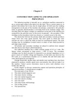
In skewed cage rotors with uninsulated bars (cast aluminum bars), there are
interbar currents (Figure 11.1a).
The treatment of various space harmonics losses at no-load follows.
R /n
q
R /n
b
R /n
q
R /n
b
R /n
q
R /n
b
R /n
q
R /n
b
R /n
q
R /n
b
R /n
q
R
er
R
er
C
(skewing)
I (y+ y)
∆
m
I
m
R - bar resistance
R - end ring segment resistance
R - bar to core resistance
er
b
q
B
r
g
y
stack
straight bars
skewed bars
S=S
n
Figure 11.1 Interbar currents (I
m
(Y)) in a skewed cage rotor a.)
and the resultant airgap flux density along stack length b.)
Depending on the relative value of the transverse (contact) resistance R
q
and
skewing c, the influence of interbar currents on fundamental rotor conductor
losses will be notable or small.
The interbar currents influence also depends on the fundamental frequency
as for f
1
= 500 Hz, for example, the skin effect notably increases the rotor cage
resistance even at rated slip.
On the other hand, skewing leaves an uncompensated rotor mmf (under
load) which modifies the airgap flux density distribution along stack length
(Figure 11.1b).
As the flux density squared enters the core loss formula, it is obvious that
the total fundamental core loss will change due to skewing.
As skewing and interbar currents also influence the space harmonics losses,
we will treat their influence once for all harmonics. The fundamental will then
become a particular case.
Fundamental core losses seem impossible to segregate in a special test
which would hold the right flux distribution and frequency. However a standstill
© 2002 by CRC Press LLC
Author: Ion Boldea, S.A.Nasar………… ………
test at rated rotor frequency f
2
= Sf
1
would, in fact, yield the actual value of
R
r
’(S
n
f
1
). The same test at various frequencies would produce precise results on
conductor fundamental losses in the rotor. The stator fundamental conductor
losses might be segregated from a standstill a.c. single-phase test with all phases
in series at rated frequency as, in this case, the core fundamental and additional
losses may be neglected by comparison.
11.3. NO-LOAD SPACE HARMONICS (STRAY NO-LOAD) LOSSES IN
NONSKEWED IMs
Let us remember that airgap field space harmonics produce on no-load in
nonskewed IMs the following types of losses:
• Surface core losses (rotor and stator)
• Tooth flux pulsation core losses (rotor and stator)
• Tooth flux pulsation cage losses (rotor)
The interbar currents produced by the space harmonics are negligible in
nonskewed machines if the rotor end ring (bar) resistance is very small (R
cr
/R
b
<
0.15).
11.3.1. No-load surface core losses
As already documented in Chapter 10, dedicated to airgap field harmonics,
the stator mmf space harmonics (due to the very placement of coils in slots) as
well the slot openings produce airgap flux density harmonics. Further on, main
flux path heavy saturation may create third flux harmonics in the airgap.
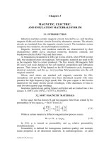
It has been shown in Chapter 10 that the mmf harmonics and the first slot
opening harmonics with a number of pole pairs ν
s
= N
s
± p
1
are attenuating and
augmenting each other, respectively, in the airgap flux density.
For these mmf harmonics, the winding factor is equal to that of the
fundamental. This is why they are the most important, especially in windings
with chorded coils where the 5th, 7th, 11th, and 17th stator mmf harmonics are
reduced considerably.
pole pitch
t
s
b
os
stator slotting
θ
m
Figure 11.2 First slot opening (airgap permeance) airgap flux density harmonics
Let us now consider the fundamental stator mmf airgap field as modulated
by stator slotting openings (Figure 11.2).
© 2002 by CRC Press LLC
Author: Ion Boldea, S.A.Nasar………… ………
() ()
msm11
0
1m10
mpN
Ncosptcos
a
aF
t,B
1s
θθ−ω
µ
=θ
±
(11.6)
This represents two waves, one with N
s
+ p
1
pole pairs and one with N
s
– p
1
pole pairs, that is, exactly, the first airgap magnetic conductance harmonic.
Let us consider that the rotor slot openings are small or that closed rotor
slots are used. In this case, the rotor surface is flat.
The rotor laminations have a certain electrical conductivity, but they are
axially insulated from each other by an adequate coating.
For frequencies of 1,200 Hz, characteristic to N
s
± p
1
harmonics, the depth
of field penetration in silicon steal for µ
Fe
= 200 µ
0
is (from 11.4) δ ≈ 0.4 mm,
for 0.6 mm thick laminations. This means that the skin effect is not significant.
Therefore we may neglect the rotor lamination-induced current reaction to
the stator field. That is, the airgap field harmonics (11.6) penetrate the rotor
without being disturbed by induced rotor surface eddy currents. The eddy
currents along the axial direction are neglected.
But now let us consider a general harmonic of stator mmf produced field
B
ν
g
.
ω−
ν
=
ω−
τ
νπ
=
ννννν
tS
R
x
cosBtS
p
x
cosBB
m
1
m
g
(11.7)
R–rotor radius; τ–pole pitch of the fundamental.
The slip for the ν
th
mmf harmonic, S
ν
, is
() ()
1
0S
1
0S
p
1S1
p
1S
ν
−=
−
ν
−=
=
=
ν
(11.8)
For constant iron permeability µ, the field equations in the rotor iron are
0B ,0Bdiv ,0rotB
z
===
νν
(11.9)
This leads to
0
y
B
x
B
0
y
B
x
B
2
y
2
2
y
2
2
x
2
2
x
2
=
∂
∂
+
∂
∂
=
∂
∂
+
∂
∂
(11.10)
In iron these flux density components decrease along y (inside the rotor)
direction
()
ω−
ν
=
ν
tS
R
x
cosyfB
m
yy
(11.11)
According to
0
y
B
x
B
y
x
=
∂
∂
+
∂
∂
.
© 2002 by CRC Press LLC
Author: Ion Boldea, S.A.Nasar………… ………
()
ω−
ν
ν
∂
∂
=
ν
tS
R
x
sin
R
y
yf
B
m
y
x
(11.12)
From (11.10),
()
()
0yf
R
y
yf
y
2
2
y
2
=
ν
−
∂
∂
(11.13)
or
()
R
y
y
eByf
ν
ν
=
(11.14)
Equation (11.14) retains one term because y < 0 inside the rotor and f
y
(y) should
reach zero for y ≈ −∞.
The resultant flux density amplitude in the rotor iron B
r
ν
is
R
y
r
eBB
ν
νν
=
(11.15)
But the Faraday law yields
dt
B
J
1
rotErot
Fe
∂
−=
σ
= (11.16)
In our case, the flux density in iron has two components B
x
and B
y
, so
t
B
z
J
t
B
z
J
y
Fe
x
x
Fe
y
∂
∂
σ−=
∂
∂
∂
∂
σ−=
∂
∂
(11.17)
The induced current components J
x
and J
y
are thus
ω−
ν
ωσ−=
ω−
ν
ωσ−=
ν
ν
νν
ν
ν
νν
tS
R
x
sinzeBSJ
tS
R
x
coszeBSJ
m
R
y
Fey
m
R
y
Fex
(11.18)
The resultant current density amplitude J
r
ν
is
zeBSJJJ
R
y
Fe
2
y
2
xr
ν
ννν
ωσ=+=
(11.19)
The losses per one lamination (thickness d
Fe
) is
© 2002 by CRC Press LLC
Author: Ion Boldea, S.A.Nasar………… ………
∫∫∫
−
−∞=
=
π
=
νν
σ
=
2/d
2/d
y
0y
R2
0x
2
r
Fe
lam
Fe
Fe
dzdydxJ
1
P
(11.20)
For the complete rotor of axial length l
stack
,
()
stack
2
Fe
22
Fe
0
Rl2
R
dSB
24
P
π
ν
ω
σ
=
ννν
(11.21)
Now, if we consider the first and second airgap magnetic conductance
harmonic (inversed airgap function) with a
1,2
(Chapter 10),
β
=
s
os
2,12,1
t
b
F
g
a
(11.22)
β(b
os,r
/g) and F
1,2
(b
os,r
/t
s,r
) are to be found from Table 10.1 and (10.14) in
Chapter 10 and
gK
1
a ;
a
a
BB
c
0
0
2,1
1g
==
ν
(11.23)
where B
g1
is the fundamental airgap flux density with
()
1
s
1
1s
1s
p
N
p
pN
1S and pN ≈
±
−=±=ν
ν
(11.24)
The no-load rotor surface losses P
o
ν
are thus
() ()
+
ππ
σ
≈
±
ν
2
0
2
2
2
1
stack
s
1
2
Fe
2
1
2
1
s
2
1g
Fe
PN
0
a
a2a
Rl2
N
Rp
df2
p
N
B
24
2P
1s
(11.25)
Example 11.1.
Let us consider an induction machine with open stator slots and 2R = 0.38 m, N
s
= 48 slots, t
s
= 25 mm, b
os
= 14 mm, g = 1.2 mm, d
Fe
= 0.5 mm, B
g1
= 0.69 T,
2p
1
= 4, n
0
= 1500 rpm, N
r
= 72, t
r
= 16.6 mm, b
or
= 6 mm, σ
Fe
= 10
8
/45 (Ωm)
-1
.
To determine the rotor surface losses per unit area, we first have to determine a
1
,
a
2
, a
0
from (11.22). For b
os
/g = 14/1.2 = 11.66 from table 10.1 β = 0.4. Also,
from Equation (10.14), F
1
(14/25) = 1.02, F
2
(0.56) = 0.10.
Also,
gK
1
a
2,1c
0
=
; K
c
(from Equations (5.3 – 5.5)) is K
c1,2
= 1.85.
Now the rotor surface losses can be calculated from (11.25).
()
()()
2
2
22
62
2
2
6
stack
0
m/W68.8245
85.1
1.04.0202.14.0
19.0105.0602
2
48
69.0
24
1022.22
Rl2
P
=
⋅+⋅
⋅
⋅⋅⋅⋅π
⋅⋅
⋅⋅
=
π
−
ν
© 2002 by CRC Press LLC
Author: Ion Boldea, S.A.Nasar………… ………
As expected, with semiclosed slots, a
1
and a
2
become much smaller; also,
the Carter coefficient decreases. Consequently, the rotor surface losses will be
much smaller. Also, increasing the airgap has the same effect. However, at the
price of larger no-load current and lower power factor of the machine. The
stator surface losses produced by the rotor slotting may be calculated in a
similar way by replacing F
1
(b
os
/t
s
), F
2
(b
os
/t
s
), β(b
os
/g) with β(b
or
/g), F
1
(b
or
/t
s
),
F
2
(b
or
/t
s
), and N
s
/p
1
with N
r
/p
1
.
As the rotor slots are semiclosed, b
or
<< b
os
, the stator surface losses are
notably smaller than those of the rotor, They are, in general, neglected.
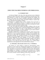
11.3.2. No-load tooth flux pulsation losses
As already documented in the previous paragraph, the stator (and rotor) slot
openings produce variation in the airgap flux density distribution (Figure 11.3).
t
s
g
b
os
max
stator tooth
flux
B
gmax
minimum
stator tooth
flux
B
gmax
a.)
φ
tooth
s
φ
0
φ
max
φ
min
π
N
r
2π
N
r
3π
N
r
θ
m
b.)
Figure 11.3 Airgap flux density as influenced by rotor and stator slotting a.)
and stator tooth flux versus rotor position b.)
In essence, the total flux in a stator and rotor tooth varies with rotor position
due to stator and rotor slot openings only in the case where the number of stator
and rotor slots are different from each other. This is, however, the case, as N
s
≠
N
r
at least to avoid large synchronous parasitic torques at zero speed (as
demonstrated in Chapter 10).
The stator tooth flux pulsates due to rotor slot openings with the frequency
()
1
r
1
rPS
p
f
N
p
S1
fNf =
−
=
, for S = 0 (no-load). The flux variation coefficient K
φ
is
© 2002 by CRC Press LLC
Author: Ion Boldea, S.A.Nasar………… ………
0
minmax
2
K
φ
φ−φ
=
φ
(11.26)
The coefficient K
φ
, as derived when the Carter coefficient was calculated in [6]
s
2
t2
g
K
γ
=
φ
(11.27)
with γ
2
as
g
b
5
g
b
or
2
or
2
+
=γ
(11.28)
Now, by denoting the average flux density in a stator tooth with B
ots
, the
flux density pulsation B
p1
in the stator tooth is
s
2
otsPs
t2
g
BB
γ
=
(11.29)
oss
s
0gots
bt
t
BB
−
=
(11.30)
B
g0
–airgap flux density fundamental.
We are now in the classical case of an iron region with an a.c. magnetic flux
density B
Ps
, at frequency f
Ps
= N
r
f/p
1
. As N
r
f/p
1
is a rather high frequency, eddy
current losses prevail, so
ght teeth weistatorG ;G
50
f
1
B
CP
steethsteeth
2
Ps
2
Ps
ep0Ps
−
= (11.29)
In (11.31), C
ep
represents the core losses at 1T and 50Hz. It could have been
for 1T and 60 Hz as well.
Intuitively, the magnetic saturation of main flux path places the pulsation
flux on a local hysteresis loop with lower (differential) permeability, so
saturation is expected to reduce the flux pulsation in the teeth. However,
Equation (11.31) proves satisfactory even in the presence of saturation. Similar
tooth flux pulsation core losses occur in the rotor due to stator slotting.
Similar formulas as above are valid.
1
sprteeth
2
Pr
2
Pr
ep0Pr
p
f
Nf ;G
50
f
1
B
CP =
=
© 2002 by CRC Press LLC
Author: Ion Boldea, S.A.Nasar………… ………
orr
r
0gotr
r
1
otrPr
bt
t
BB ;
t2
g
BB
−
=
γ
=
(11.32)
g
b
5
g
b
os
2
os
1
+
=γ
As expected, C
ep
– power losses per Kg at 1T and 50 Hz slightly changes
when the frequency increases, as it does at
1
s
p
f
N
or
1
r
p
f
N
. C
ep
= C
e
K, with K
= 1.1 – 1.2 as an empirical coefficient.
Example 11.2
For the motor in Example 10.1, let us calculate the tooth flux pulsation losses
per Kg of teeth in the stator and rotor.
Solution
In essence, we have to determine the flux density pulsations B
Ps
, B
Pr
, then
f
Ps
, f
Pr
and apply Equation (11.31).
From (11.26) and (11.32),
5.2
2.1
6
5
2.1
6
g
b
5
g
b
2
or
2
or
2
=
+
=
+
=γ
166.8
2.1
14
5
2.1
14
g
b
5
g
b
2
os
2
os
1
=
+
=
+
=γ
()
T094.0
14252
2.15.269.0
t2
g
bt
t
BB
s
2
ors
s
0gPs
=
−
⋅⋅
=
γ
−
=
()
T3189.0
66.162
2.1166.869.0
t2
g
bt
t
BB
r
1
orr
r
0gPr
=
−
⋅⋅
=
γ
−
=
With C
ep
= 3.6 W/Kg at 1T and 60 Hz,
Kg/W3643.59
502
6072
1
094.0
6.3
50
f
1
B
CP
222
Pr
2
Ps
epPs
=
⋅
⋅
=
=
© 2002 by CRC Press LLC
Author: Ion Boldea, S.A.Nasar………… ………
Kg/W66.303
502
6048
1
3189.0
6.3
50
f
1
B
CP
22
2
Ps
2
Pr
epPr
=
⋅
⋅
=
=
The open slots in the stator produce large rotor tooth flux pulsation no-load
specific losses (P
Pr
).
The values just obtained, even for straight rotor (and stator) slots, are too
large.
Intuitively we feel that at least the rotor tooth flux pulsations will be notably
reduced by the currents induced in the cage by them. At the expense of no-load
circulating cage-current losses, the rotor flux pulsations are reduced.
Not so for the stator unless parallel windings are used where circulating
currents would play the same role as circulating cage currents.
When such a correction is done, the value of B
Pr
is reduced by a subunitary
coefficient, [4]
1
s
Prdk
1r
tkPrPr
p
N
K ;BK
R2
pKt
sinKB'B ==
⋅⋅=
(11.33)
−+++
+
−=
1
K
1
LLLL
LL
1K
skewk
2
mkslotdk2mk
dk2mk
tk
(11.34)
where L
mk
is the magnetizing inductance for harmonic K, L
2dk
the differential
leakage inductance of K
th
harmonic, K
skewk
the skewing factor for harmonic K,
and L
slot
– rotor slot leakage inductance.
2
mmk
K
1
LL ≈
(11.35)
mkdk2dlkdk2
LKL ⋅τ⋅≈
(11.36)
Fe
Fe
Fe
Fe
dlk
2
d
2
d
tanhK
δ
δ
=
; d
Fe
– lamination thickness;
FekFediff
Fe
S
2
ωσµ
=δ
(11.37)
where
µ
Fediff
is the the iron differential permeability for given saturation level of
fundamental.
1
s
kk
p
N
2f2S
π=π=ω
(11.38)
© 2002 by CRC Press LLC
Author: Ion Boldea, S.A.Nasar………… ………
1
R
Kp
sin
R
Kp
2
1
1
dk2
−
π
π
=τ
(11.39)
R
cKp
R
cKp
sin
K
1
1
skewk
=
(11.40)
Skewing is reducing the cage circulating current reaction which increases
the value of K
tk
and, consequently, the teeth flux pulsation core losses stay
undamped.
Typical values for K
dk
–the total damping factor due to cage circulating
currents–would be in the range K
dk
= 1 to 0.05, depending on rotor number
slots, skewing, etc.
A skewing of one stator slot pitch is said to reduce the circulating cage
reaction to almost zero (K
dk
≈ 1), so the rotor tooth flux pulsation losses stay
high. For straight rotor slots with K
dk
≈ 0.1 – 0.2, the rotor tooth flux pulsation
core losses are reduced to small relative values, but still have to be checked.
11.3.3. No-load tooth flux pulsation cage losses
Now that the rotor tooth flux pulsation, as attenuated by the corresponding
induced bar currents, is known, we may consider the rotor bar mesh in Figure
11.4.
R
bk
I
(1)
bk
I
(2)
bk
∆φ
rk
Figure 11.4 Rotor mesh with two bars
()
stackorrprkdkrk
lbtBK
−=φ∆
(11.41)
In our case,
1
s
p
N
K
=
. For this harmonic, the rotor bar resistance is
increased due to skin effect by K
Rk
(
1
1
s
k
f
p
N
f =
).
© 2002 by CRC Press LLC
Author: Ion Boldea, S.A.Nasar………… ………
The skin effect in the end ring is much smaller, so the ring resistance may
be neglected. If we also neglect the leakage reactance in comparison with rotor
bar resistance, the equation of the mesh circuit in Figure 11.4 becomes
() ( )
(
)
2
bk
1
bk
Rkbrk
IIKRfK2
−=φ∆π
(11.42)
The currents I
bk
in the neighbouring bars (1) and (2) are phase shifted by an
angle
r
s
N
N
2
π
, so
() ( )
r
s
bk
2
bk
1
bk
N
N
sinI2II π=−
(11.43)
From (11.41) and (11.42),
Rkb
r
s
rk
bk
KR
N
N
sin2
fK2
I
π
πφ∆
=
(11.44)
Finally, for all bars, the cage losses for harmonic K are
2
bk
Rkbrocagek
2
I
KRNP
=
(11.45)
or
()()
Rkb
r
s
2
2
1
s
22
rk
r
ocagek
KR
N
N
sin
p
N
f2
8
N
P
π
πφ∆
≈
(11.46)
Expression (11.46) is valid for straight rotor slots. In a skewed rotor, the
rotor tooth flux pulsation is reduced (per stack length) and, thus, the
corresponding no-load cage losses are also reduced. They should tend to zero
for one stator slot pitch skewing.
Example 11.3. Consider the motor in Example 11.1, 11.2 with the stack length
l
stack
= 0.4 m, rotor bar class section A
bar
= 250 mm
2
, (N
s
= 48, N
r
= 72, 2p
1
= 4).
The rotor bar skin effect coefficient for
Hz144060
2
48
f
p
N
f
1
s
k
=⋅==
is K
Rk
=
15. Let us calculate the cage losses due to rotor tooth flux pulsations if the
attenuating factor of K
dk
= 0.05.
Solution
With K
dk
= 0.05 and B
pr
= 0.3189, from Example 11.2 we may calculate ∆φ
k
(from 11.41).
© 2002 by CRC Press LLC
Author: Ion Boldea, S.A.Nasar………… ………
() ( )
Wb10067.0
4.01066.163189.005.0lbtBK
3
3
stackorrprkdkrk
−
−
⋅=
=⋅⋅−⋅⋅=−=φ∆
The d.c. bar resistance R
b
is
Ω⋅=
⋅⋅
=
σ
≈
−
−
4
76
Albar
stack
b
10533.0
100.3
1
10250
4.01
A
l
R
So the bar current
()
1
r
p
N
K
bk
I
=
is (11.43)
A443
1510533.0
72
48
sin2
2
48
60210067.0
I
4
3
bk
=
⋅⋅⋅π
⋅π⋅⋅
=
−
−
This is indeed a large value, but let us remember that the rotor bars are
many (N
r
>> N
s
) and the stator slots are open, with a small airgap.
Now the total rotor flux pulsation losses P
ocagek
are (11.45)
W2.56821510533.0
2
443
72P
4
2
cagek0
=⋅⋅⋅
⋅=
−
Let us compare this with the potential power of the IM under consideration
(f
x
= 3⋅10
4
N/cm
2
– specific force),
kW427
2
502
4.019.02103
p
f2
RLR2fP
24
1
xn
≈
π
⋅⋅⋅π⋅⋅=
π
⋅⋅⋅π⋅≈
In such a case, the no-load cage losses would represent more than 1% of all
power.
11.4. LOAD SPACE HARMONICS (STRAY LOAD) LOSSES
IN NONSKEWED IMs
Again, slot opening and mmf space harmonics act together to produce space
harmonics load (stray load) losses in the presence of larger stator and rotor
currents.
In general, the no-load stray losses are augmented by load, component by
component. The mmf space harmonics of the stator, for integral-slot windings,
is
()
1
p1c6 ±=ν
(11.47)
The slot opening (airgap magnetic conductance) harmonics are
1s1s
pNc ±=ν
(11.48)
As expected, they overlap. The first slot harmonics (c
1
= 1) ν
smin
= N
s
± p
1
are most important as their winding factor is the same as for the fundamental.
© 2002 by CRC Press LLC
Author: Ion Boldea, S.A.Nasar………… ………
The mmf harmonic F
ν
amplitude is
ν
=
ν
ν
1
1w
w
1
p
K
K
FF
(11.49)
where K
w1
and K
w
ν
are the winding factors of the fundamental and of harmonic
ν, respectively.
If the number of slots per pole and phase (q) is not very large, the first slot
(opening) harmonics N
s
± p
1
produce the largest field in the airgap.
Only for full – pitch windings may the phase belt mmf harmonics (ν = 5, 7,
11, 13) produce airgap fields worthy of consideration because their winding
factors are not small enough (as they are in chorded coil windings). However,
even in such cases, the losses produced by the phase belt mmf harmonics may
be neglected by comparison with the first slot opening harmonics N
s
± p
1
. [6]
Now, for these first slot harmonics, it has been shown in Chapter 10 that
their mmf companion harmonics of same order produce an increase for N
s
– p
1
and a decrease for N
s
+ p
1
, [6]
()
1
K
1
a2
a
p
pN
1
c0
1
1
1s
0pN
1s
>
−
+=ξ
−
(11.50)
()
1
K
1
a2
a
p
pN
1
c0
1
1
1s
0pN
1s
<
+
−=ξ
+
where a
1
, a
0
, K
s
have been defined earlier in this chapter for convenience.
For load conditions, the amplification factors
()
0pN
1s
−
ξ
and
()
0pN
1s
+
ξ
are to be
replaced by [6]
()
()
()
()
2
0
1
1
1s
n
0
0
1
1
1s
n
0
n
c
npN
2
0
1
1
1s
n
0
0
1
1
1s
n
0
n
c
npN
a2
a
p
pN
I
I
a2
a
p
pN
I
I
sin21
K
1
a2
a
p
pN
I
I
a2
a
p
pN
I
I
sin21
K
1
1s
1s
+
+
+
ϕ−=ξ
−
+
−
ϕ+=ξ
+
−
(11.51)
I
0
is the no-load current, I
n
the current under load, and ϕ
n
the power factor
angle on load.
From now on using the above amplification factors, we will calculate the
correction coefficients for load to multiply the various no-load stray losses and
thus find the load stray losses.
Based on the fact that losses are proportional to harmonic flux densities
squared, for N
s
± P
1
slot harmonics we obtain
• Rotor surface losses on load
The ratio between load P
0n
and no-load P
00
surface losses C
loads
is
© 2002 by CRC Press LLC
Author: Ion Boldea, S.A.Nasar………… ………
1C ;CPP
loadsloads00n0
>⋅=
(11.52)
() ()
() ()
ξ
+
+ξ
−
ξ
+
+ξ
−
=
+−
+−
0pN
2
2
1s
1
0pN
2
2
1s
1
npN
2
2
1s
1
npN
2
2
1s
1
2
0
n
loads
1s1s
1s1s
pN
p
pN
p
pN
p
pN
p
I
I
C
(11.53)
• Tooth flux pulsation load core losses
For both stator and rotor, the no-load surface P
sp0
, P
rp0
are to be augmented
by amplification coefficients similar to C
load
,
loads0rprpn
loadr0spspn
CPP
CPP
⋅=
⋅=
(11.54)
where C
loadr
is calculated with N
r
instead of N
s
.
• Tooth flux pulsation cage losses on load
For chorded coil windings the same reasoning as above is used.
loadrcage0ncage
CPP ⋅=
(11.55)
For full pitch windings the 5
th
and 7
th
(phase belt) mmf harmonics losses are
to be added.
The cage equivalent current I
r
ν
produced by a harmonic ν is
ν
ν
ν
ν
ν
τ+
=
τ+
ν
1
p
K
K
F
1
F
~I
1
1w
w
1r
(11.56)
τ
ν
is the leakage (approximately differential leakage) coefficient for harmonic ν
(τ
ν
≈ τ
d
ν
).
The cage losses,
ννν Rb
2
rr
KRI~P
(11.57)
K
R
ν
is, again, the skin effect coefficient for frequency f
ν
.
()
S1
p
1S ;fSf
1
1
−
ν
−==
ννν
(11.58)
The differential leakage coefficient for the rotor (Chapter 6),
1
N
sin
1
N
2
r
2
2
r
d
−
πν
πν
=τ
ν
(11.59)
© 2002 by CRC Press LLC
Author: Ion Boldea, S.A.Nasar………… ………
Equation (11.57) may be applied both for 5
th
and 7
th
(5p
1
, 7p
1
), phase belt,
mmf harmonics and for the first slot opening harmonics N
s
± p
1
.
Adding these four terms for load conditions [6] yields
()
()
() ()
ξ+ξ
τ+
τ+
+⋅≈
+−
2
nPN
2
nPN
s
1
2
6d
2
dN
2
1w
5w
loadrcage0ncage
1s1s
s
N
p6
1
1
K
K
2
1CPP
(11.60)
()
()
π
π
=τ+
π
π
=τ+
r
s
2
2
r
s
dN
r
1
2
2
r
1
6d
N
N
sin
N
N
1 ;
N
p6
sin
N
p6
1
s
(11.61)
Magnetic saturation may reduce the second term in (11.60) by as much as
60 to 80%. We may use (11.61) even for chorded coil windings, but, as K
w5
is
almost zero, the factor in parenthesis is almost reduced to unity.
Example 11.4. Let us calculate the stray load amplification with respect to no-
load for a motor with nonskewed insulated bars and full pitch stator winding;
open stator slots, a
0
= 0.67/g, a
1
= 0.43/g, I
0
/I
n
= 0.4, cosϕ
n
= 0.86, N
s
= 48, N
r
=
40, 2p
1
= 4, β = 0.41, K
c
= 1.8.
Solution
We have to first calculate from (11.50) the amplification factors for the
airgap field N
s
± P
1
harmonics by the same order mmf harmonics.
()
()
cc0
1
1
1s
c
0pN
K
4.8
67.02
43.0
2
248
1
K
1
a2
a
p
pN
1
K
1
1s
=
⋅
⋅
−
+=
−
+=ξ
−
()
()
cc0
1
1
1s
c
0pN
K
7
67.02
43.0
2
248
1
K
1
a2
a
p
pN
1
K
1
1s
−
=
⋅
⋅
−
−=
+
−=ξ
+
Now, the same factors under load are found from (11.51).
()
c
2
c
npN
K
6.3
67.02
43.0
2
248
4.0
67.02
43.0
2
248
4.053.021
K
1
1s
=
⋅
⋅
−
⋅+
⋅
⋅
−
⋅⋅⋅+=ξ
−
()
c
2
c
npN
K
8.2
67.02
43.0
2
248
4.0
67.02
43.0
2
248
4.053.021
K
1
1s
=
⋅
⋅
+
⋅+
⋅
⋅
+
⋅⋅⋅−=ξ
+
The stray loss load amplification factor C
loads
is (11.53)
© 2002 by CRC Press LLC
Author: Ion Boldea, S.A.Nasar………… ………
() ()
() ()
!0873.1
74.8
80.260.3
4.0
1
I
I
C
22
22
2
0pN
2
0pN
2
npN
2
npN
2
2
0
n
loads
1s1s
1s1s
=
+
+
=
ξ+ξ
ξ+ξ
≈
+−
+−
So the rotor surface and the rotor tooth flux pulsation (stray) load losses are
increased at full load only by 8.73% with respect to no-load.
Let us now explore what happens to the no-load rotor tooth pulsation (stray)
cage losses under load. This time we have to use (11.60),
()
()
() ()
ξ+ξ
τ+
τ+
+⋅=
+− npN
2
npN
2
s
1
2
6d
2
dN
2
1w
5w
s
load
cage0
ncage
1s1s
s
N
p6
1
1
K
K
K2
1C
P
P
with K
s
a saturation factor (K
s
= 0.2), K
w5
= 0.2, K
w1
= 0.965. Also τ
d48
and τ
d6
from (11.61) are τ
d48
= 42, τ
d6
= 0.37. Finally,
()
()
!43.1
80.260.3
48
26
37.01
421
965.0
2.0
2.02
10873.1
P
P
22
2
2
2
cage0
ncage
=
+
⋅
+
+
⋅
+⋅=
As expected, the load stray losses in the insulated nonskewed cage are
notably larger than for no-load conditions.
11.5. FLUX PULSATION (STRAY) LOSSES IN SKEWED INSULATED
BARS
When the rotor slots are skewed and the rotor bars are insulated from rotor
core, no interbar currents flow between neighboring bars through the iron core.
In this case, the cage no-load stray losses P
0cage
due to first slot (opening)
harmonics N
s
± p
1
are corrected as [6]
()
()
()
()
−
π
−
π
+
+
π
+
π
=
2
1s
ss
1s
ss
2
1s
ss
1s
ss
cage0
cages0
pN
Nt
c
pN
Nt
c
sin
pN
Nt
c
pN
Nt
c
sin
2
P
P
(11.62)
where c/t
s
is the skewing in stator slot pitch t
s
units.
When skewing equals one stator slot pitch (c/t
s
= 1), Equation (11.62)
becomes
()
2
s
1
cage0
1t/c
cages0
N
p
PP
s
⋅≈
=
(11.63)
© 2002 by CRC Press LLC
Author: Ion Boldea, S.A.Nasar………… ………
Consequently, in general, skewing reduces the stray losses in the rotor
insulated (on no-load and on load) as a bonus from (11.60). For one stator pitch
skewing, this reduction is spectacular.
Two things we have to remember here.
•
When stray cage losses are almost zero, the rotor flux pulsation core losses
are not attenuated and are likely to be large for skewed rotors with insulated
bars.
• Insulated bars are made generally of brass or copper.
For the vast majority of small and medium power induction machines, cast
aluminum uninsulated bar cages are used. Interbar current losses are expected
and they tend to be augmented by skewing.
We will treat this problem separately.
11.6. INTERBAR CURRENT LOSSES IN
NONINSULATED SKEWED ROTOR CAGES
For cage rotor IMs with skewed slots (bars) and noninsulated bars,
transverse or cross-path or interbar additional currents occur through rotor iron
core between adjacent bars.
Measurements suggest that the cross-path or transverse impedance Z
d
is, in
fact, a resistance R
d
up to at least f = 1 kHz. Also, the contact resistance between
the rotor bar and rotor teeth is much larger than the cross-path iron core
resistance. This resistance tends to increase with the frequency of the harmonic
considered and it depends on the manufacturing technology of the cast
aluminum cage rotor. To have a reliable value of R
d
, measurements are
mandatory.
I
rm
C
(skewing)
I (y+ y)
∆
bm
BA
I (y+ y)
∆
bm+1
I
rm+1
end ring
I (y+ y)
∆
dm
I (y)
bm
I (y)
dm
I (y+ y)
∆
dm+1
I (y)
bm+1
I (y)
dm+1
CD
x
y
0
γ
bar
m
bar
m+1
I
rm
l
stack
l /2
stack
end ring
I
I
ν2π
N
r
bm
bm+1
Figure 11.5 Bar and interbar currents in a rotor cage with skewed slots
© 2002 by CRC Press LLC
Author: Ion Boldea, S.A.Nasar………… ………
To calculate the interbar currents (and losses), a few analytical procedures
have been put forward [9, 6, 10]. While [9, 10] do not refer especially to the
first slot opening harmonics, [6] ignores the end ring resistance.
In what follows, we present a generalization of [9, 11] to include the first
slot opening harmonics and the end ring resistance.
Let us consider the rotor stack divided into many segments with the interbar
currents lumped into definite resistances (Figure 11.5).
The skewing angle γ is
stack
l
c
tan
=γ
(11.64)
What airgap field harmonics are likely to produce interbar currents? In
principle, all space harmonics, including the fundamental, do so. Additionally,
time harmonics have a similar effect. However, for chorded coil stator windings,
the first slot harmonic N
s
– p
1
is augmented by the same stator mmf harmonic;
N
s
+ p
1
harmonic is attenuated in a similar way as shown in previous
paragraphs.
Only for full-pitch stator windings, the losses produced by the first two 5
th
and 7
th
phase belt stator mmf harmonics are to be added. (For chorded coil
windings, their winding factors, and consequently their amplitudes, are
negligible).
At 50(60) Hz apparently the fundamental component losses in the cross-
path resistance for skewed noninsulated bar rotor cages may be neglected.
However, this is not so in high (speed) frequency IMs (above 300Hz
fundamental frequency). Also, inverter fed IMs show current and flux time
harmonics, so additional interbar current losses due to the space fundamental
and time harmonics are to be considered. Later in this chapter, we will return to
this subject.
For the time being, let us consider only one stator frequency f with a general
space harmonic ν with its slip S
ν
.
Thus, even the case of time harmonics can be dealt with one by one
changing only f, but for ν = p
1
(pole pairs), the fundamental.
The relationship between adjacent bar and cross-path resistance currents on
Figure 11.5 are
() () ()
() () ()
r
rm
N
j
1rmrm
r
dm
N
j
1dmdm
r
bm
N
j
1bmbm
N
sinIje2II
N
sinyIje2yIyI
N
sinyIje2yIyI
r
r
r
πν
=−
πν
=−
πν
=−
πν
−
+
πν
−
+
πν
−
+
(11.65)
© 2002 by CRC Press LLC
Author: Ion Boldea, S.A.Nasar………… ………
Kirchoff’s first law in node A yields
() ()
() ()
y
yIyyI
yyIyyI
1bmbm
1dmdm
∆
−∆+
≈∆+−∆+
+
+
(11.66)
Note that the cross path currents I
dm
, I
dm+1
refer to unity stack length.
With (11.65) in (11.66), we obtain
() ()
yI
dy
d
N
sin2
e
jyI
bm
r
N
j
dm
r
⋅
πν
−≈
πν
−
(11.67)
Also, for the ring current I
rm
,
()
2
l
y
1bm1rmrm
stack
III
=
++
=−
(11.68)
with (11.65), (11.68) becomes
()
2
l
y
bm
r
N
j
rm
stack
r
I
N
sin2
e
jI
=
πν
−
πν
=
(11.69)
The second Kirchoff’s law along the closed path ABCD yields
()()()()()
() ()()
stack
l
yj
m
stack
1bmbm
d0bdmdmstackd
l
y
eE
l
y
yIyI
1XjSRyIyyIlR
stack
∆
⋅⋅=
∆
⋅−⋅
⋅τ+++−∆+
γν
−
ν
+
νννν
(11.70)
E
m
ν
represents the stator current produced induced voltage in the contour
ABCD. X
0
ν
represents the airgap reactance for harmonic ν seen from the rotor
side; τ
d
ν
is the differential leakage coefficient for the rotor (11.59).
Making use of (11.67) into (11.70) yields
()
()
stack
l
y
j
mbmbe
2
bm
2
2
stackde
eEyIZ
dy
yId
lR
γν
−
ν
=−
(11.71)
The boundary conditions at y = ±l
stack
/2 are
() ()
r
2
d
destackd
2/ly
dmer
2/ly
rm
N
sin4
R
R ;lRIZI
stack
stack
νπ
==⋅
±=
±=
m
(11.72)
Z
er
represents the impedance of end ring segment between adjacent bars.
© 2002 by CRC Press LLC
Author: Ion Boldea, S.A.Nasar………… ………
bebebe
r
2
er
ereererer
jXRZ ;
N
sin4
Z
Z ;jXRZ +=
νπ
=+=
νν
(11.73)
R
er
ν
, X
er
ν
are the resistance and reactance of the end ring segment. Z
be
is bar
equivalent impedance.
Solving the differential Equation (11.71) with (11.72) yields [10]
()
()
−−
γν
−
γν
⋅
⋅
γν+
−
=
ν
de
be
stackde
be
stackstackstack
stackde
22
be
m
bm
R
Z
l
y
sinhB
R
Z
l
y
coshA
l
y
sinj
l
y
cos
lRZ
E
yI
(11.74)
The formula of the cross-path current I
dm
(y) is obtained from (11.67) with
(11.74).
Also,
+
νγ
νγ−
νγ
=
de
be
de
be
de
de
be
ere
deere
R
Z
2
1
sinh
R
Z
R
R
Z
2
1
coshZ
2
sinR
2
cosZ
A
(11.75)
+
νγ
νγ−
νγ
−=
de
be
de
be
de
de
be
ere
deere
R
Z
2
1
cosh
R
Z
R
R
Z
2
1
sinhZ
2
cosR
2
sinZ
jB
(11.76)
When the skewing is zero (γ = 0), B = 0 but A is not zero and, thus, the bar
current in (11.74) still varies along y (stack length) and therefore some cross-
path currents still occur. However, as the end ring impedance Z
ere
tends to be
small with respect to R
de
, the cross-path currents (and losses) are small.
However, only for zero skewing and zero end ring impedance, the interbar
current (losses) are zero (bar currents are independent of y). Also, as expected,
for infinite transverse resistance (Rde ~ ∞), again the bar current does not
depend on y in terms of amplitude. We may now calculate the sum of the bar
losses and interbar (transverse) losses together,
d
cage
P
ν
.
() ()
++=
∫∫
−−
ν
2
rmer
2
l
2
l
2
dmstackd
2
l
2
l
stack
b
2
bmr
d
cage
IR2dyyIlRdy
l
R
yINP
stack
stack
stack
stack
(11.77)
Although (11.77) looks rather cumbersome, it may be worked out rather
comfortably with I
bm
(bar current) from (11.74), I
dm
from (11.67), and I
rm
from
(11.69).
© 2002 by CRC Press LLC
Author: Ion Boldea, S.A.Nasar………… ………
We still need the expressions of emfs E
m
ν
which would refer to the entire
stack length for a straight rotor bar pair.
value)(RMS ;
2
leBBV
E
stack
N
2
j
r
m
r
−
=
νπ
−
ννν
ν
(11.78)
V
r
ν
is the field harmonic ν speed with respect to the rotor cage and B
ν
the ν
th
airgap harmonic field. For the case of a chorded coil stator winding, only the
first stator slot (opening) harmonics ν = N
s
± p
1
are to be considered.
For this case, accounting for the first airgap magnetic conductance
harmonic, the value of B
ν
is
()
11ss
0
1
g1N
ppNN ;
2a
a
BB
s
m±==
(11.79)
a
1
and a
0
from (11.22 and 11.23).
The speed V
r
ν
is
ν
±
π
=
ν
1
1
r
p
1
60p
f2
RV
(11.80)
with
s
N
1
r1s
V
60p
f2
RV pN =
π
≈±=ν
ν
(11.81)
The airgap reactance for the ν = N
s
± p
1
harmonics, X
0
ν
, is
s
1
p0N0
N
p
XX
s
≈
(11.82)
X
0p
, the airgap reactance for the fundamental, as seen from the rotor bar,
r
2
w1
2
1
2
m
p0
N
KW34
;
X
X
⋅⋅
=α
α
=
(11.83)
where X
m
is the main (airgap) reactance for the fundamental (reduced to the
stator),
()
sc1
stack
2
w1
2
1
2
10
m
K1gKp
lKW6
X
+
τ
π
ωµ
=
(11.84)
(For the derivation of (11.83), see Chapter 5.) W
1
–turns/phase, K
w1
–winding
factor for the fundamental, K
s
–saturation factor, g–airgap, p
1
–pole pairs, τ–pole
pitch of stator winding.
Now that we have all data to calculate the cage losses and the transverse
losses for skewed uninsulated bars, making use of a computer programming
© 2002 by CRC Press LLC
Author: Ion Boldea, S.A.Nasar………… ………
environment like Matlab etc., the problem could be solved rather comfortably in
terms of numbers.
Still we can hardly draw any design rules this way. Let us simplify the
solution (11.74) by considering that the end ring impedance is zero (Z
er
= 0) and
that the contact (transverse) resistance is small.
• Small transverse resistance
Let us consider R
q
= R
dl
⋅l
stack
, the contact transverse resistance per unit rotor
length and that R
q
is so small that
()
stack
d0
r
2
2
q
l
1X
N
sin4
R
R
νν
τ+
νπ
<<
νγ
(11.85)
For this case in [6], the following solution has been obtained:
()
()
()
R
1
n
l
1X
N
sin2
ejE
I ;
1X
ejE
yI
stack
d0
r
l
y
j
m
dm
d0
l
y
j
m
bm
stackstack
γ
τ+
νπ
−
=
τ+
−
=
νν
νγ
−
ν
νν
νγ
−
ν
(11.86)
n–the number of stack axial segments.
The transverse losses P
d0
are
2
d
2
0
m
2
3
r
stack
q
0d
R
c
1
1
X
E
4
N
l
R
P
⋅
τ+
⋅
π
≈
νν
ν
(11.87)
The bar losses P
b0
are:
()
()
2
d
0
2
2
m
ber0b
1X
E
RNP
ν
ν
ν
τ+
=
(11.88)
Equations (11.87 and 11.88) lead to remarks such as
• For zero end ring resistance and low transverse resistance R
d
, the transverse
(interbar) rotor losses P
d
are proportional to R
d
and to the skewing squared.
• The bar losses are not influenced by skewing (11.88), so skewing is not
effective in this case and it shall not be used.
• Large transverse resistance
In this case, the opposite of (11.85) is true. The final expressions of
transverse and cage losses P
d0
, P
b0
are
()
2
R
R2
l
sin
3
1
1
1
1
l
R
c
l
E
N
2
P
q
stack
2
d
3
stack
2
2
stack
m
r
2
0q
ν
−
⋅
τ+
⋅
π
≈
ν
ν
(11.89)
© 2002 by CRC Press LLC