International Journal of Machine Tools & Manufacture pot
Bạn đang xem bản rút gọn của tài liệu. Xem và tải ngay bản đầy đủ của tài liệu tại đây (999.45 KB, 7 trang )
Simulation of an active vibration control system in a centerless grinding
machine using a reduced updated FE model
M.H. Fernandes
a
, I. Garitaonandia
a,
Ã
, J. Albizuri
b
, J.M. Herna
´
ndez
a
, D. Barrenetxea
c
a
Faculty of Mining Engineering, Department of Mechanical Engineering, University of the Basque Country, Colina de Beurko s/n, 48902 Barakaldo, Spain
b
Faculty of Engineering, Department of Mechanical Engineering, University of the Basque Country, Alameda de Urquijo s/n 48013 Bilbao, Spain
c
IDEKO Pol. Industrial de Arriaga, 2. 20870 Elgoibar, Spain
article info
Article history:
Received 22 August 2008
Received in revised form
28 October 2008
Accepted 13 November 2008
Available online 27 November 2008
Keywords:
Centerless grinding
Active control
Modelling
Vibration simulation
abstract
In this paper, a novel and complete process to simulate an active vibration control system in a centerless
grinding machine is presented. Based on the updated finite element (FE) model of the machine, the
structural modifications performed to incorporate active elements are detailed, as well as the
subsequent reduction procedure to obtain a low-order state space model. This reduced structural model
was integrated in the cutting process model giving a tool adapted for the purpose of simulating different
control laws. Using the developed model, a control algorithm, which previously had been implemented
in the centerless grinding machine under study, was checked. The simulation results were in agreement
with the experimentally obtained ones, showing that the designed model is able to reproduce machine
behaviour with the control activated. This model constitutes a powerful tool to evaluate the
effectiveness of different approaches to that of the described one, making it possible to tackle an
optimisation process of the control system by means of simulations and, thus, avoiding the costs that
would involve the practical implementation of each one.
& 2008 Elsevier Ltd. All rights reserved.
1. Introduction
One of the most important problems limiting the circularity of
round parts in centerless grinding is the occurrence of self-excited
vibrations caused by regenerative chatter. Due to the fact that this
process is usually used to machine cylindrical elements with high
surface finish requirements, the appearance of roundness errors is
undesirable, and the study of procedures to minimize this
negative effect has aroused the interest of several researchers.
Traditionally, the developed solutions consist of avoiding the
unstable operating regions through an adequate selection of set-
up conditions, combining properly the geometric configuration of
the machine with workpiece rotational speed [1–5]. However,
from a productivity point of view, these solutions are not
necessarily the recommended ones because the optimum cutting
conditions can differ from the chatter-free configurations.
Other procedures have been based on structural modifications
to stiffen the most flexible components in the force transmission
loop [6,7]. This stiffening produces an increase in the first
resonant frequency, widening the low workpiece rotational speed
stability zone. Nevertheless, such an alternative involves a
redesign of the machine structure, giving rise to solutions that
can be economically unfeasible.
Taking into account the above-mentioned limitations, Albizuri
et al. [8] proposed a novel approach based on the application of
active vibration control. Using commercial piezoelectric actuators
(A) in a feedback loop, they reduced the structural vibration level
and, consequently, the roundness errors of the workpieces.
Although the results they obtained were promising, they were
presented without a previous mathematical development, which
would allow them to optimise the active vibration system by
means of simulations, concerning both the programmed con-
trollers and the used sensors and actuators.
Later, Garitaonandia et al. [9] characterized the dynamic
properties of the machine combining finite element (FE) model
updating and model order reduction techniques. The proposed
approach was effective for the estimation of machine dynamic
behaviour under usual cutting conditions, but the study was not
extended to the simulation of any active vibration control scheme.
The availability of a theoretical model describing both the
structural and the controller characteristics is of major interest, as
it permits one to predict the effectiveness of different control
alternatives, giving insight into their behaviour before their
practical implementation and providing valuable information to
select the most suitable one. Therefore, the high costs (both
economic and time costs), involving the experimental evaluation
of each possible solution to make this selection, can be avoided.
ARTICLE IN PRESS
Contents lists available at ScienceDirect
journal homepage: www.elsevier.com/locate/ijmactool
International Journal of Machine Tools & Manufacture
0890-6955/$ -see front matter & 2008 Elsevier Ltd. All rights reserved.
doi:10.1016/j.ijmachtools.2008.11.002
Ã
Corresponding author. Tel.: +34946017815; fax: +34946017800.
E-mail address: (I. Garitaonandia).
International Journal of Machine Tools & Manufacture 49 (2009) 239–245
Motivated by the benefits that can be obtained with a model
having the described characteristics, in this paper a theoretical
model derived from the FE formulation is developed to simulate
the active vibration control system that had been previously
implemented in [8]. Practical results obtained in the same
reference will be used to evaluate the accuracy of the simulated
predictions, thus validating the model.
2. FE model
The simulation procedure presented in this paper is based on
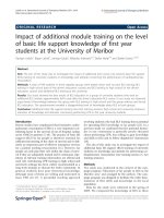
the updated FE model developed in [9]. Fig. 1 shows this model,
where for greater clarity only solid models of the components
have been shown. It consists of 53,200 nodes and 37,807
elements.
As is reported in [9], this model predicted accurately the
chatter behaviour observed in different machining tests. In these
tests, the most violent vibrations appeared when the main chatter
mode was excited at frequencies close to 55 Hz, where an
important displacement of the lower slide relative to the swivel
plate was presented in the longitudinal Z direction (see Fig. 1).
Other less-severe vibrations were detected at about 130 Hz when
the secondary chatter mode was excited, dominated by a local
bending deformation of the workblade.
3. Integration of the actuators in the FE model
To simulate the active control system, it is necessary to modify
the FE model in order to incorporate the piezoelectric actuators.
With this purpose, the design presented in [8] was followed,
where two PI-247.30 piezoelectric actuators had been placed in
the upper spindle support (D) area to obtain a strong control
authority on the main chatter mode. This design is depicted in
Fig. 2, where it can be seen that the integration of the actuators
requires a design modification of the upper spindle support in
such a way that two holes are made in it.
Each actuator, which is located collinear to a force transducer
(B), exerts the control force on its left side (according to Fig. 2)
over support D and on its right side over an auxiliary component
(E) that connects the two actuator-force transducer groups. This
component transfers the two control forces to the lower spindle
(C). Therefore, both actuators are placed in a parallel configuration
in the loading path from the lower slide to the swivel plate, and
they transmit the force to the lower spindle in a series
configuration.
Piezoelectric actuators like the ones used in this application
consist of n-stacked ceramic layers of PZT material (lead–zirco-
nate–titanate) that change in length when electrically charged. An
important aspect to consider is the modelling of the force they
exert. The relation among the externally applied voltage (V
pzt
), the
axial deformation of an actuator (
D
L) and the actuator-force (F
pzt
)
is [10],
F
pzt
¼ K
pzt
ðd
33
nV
pzt
À
D
LÞ, (1)
where K
pzt
represents the actuator stiffness and d
33
is the
piezoelectric constant. Defining z as the vector containing the
displacements of the different nodes in the FE model, the axial
deformation of an actuator can be expressed by the following
relation:
D
L ¼ b
T
z, (2)
where b is the influence vector of the axial end displacements of
the actuator.
Substituting Eq. (2) into Eq. (1) and considering the centerless
grinding machine structure formed by its mass matrix M, its
damping matrix C and its stiffness matrix K, the incorporation of
the forces exerted by the actuators in the equation of motion
governing the dynamic equilibrium leads to [11],
ARTICLE IN PRESS
Fig. 1. Updated FE model of the centerless grinding machine.
Fig. 2. Detail of piezoelectric actuators location area.
M.H. Fernandes et al. / International Journal of Machine Tools & Manufacture 49 (2009) 239–245240
M
€
z þ C
_
z þðK þ K
pzt
b
1
b
T
1
þ K
pzt
b
2
b
T
2
Þz ¼ L
u
F
n
þ b
1
K
pzt
 d
33
nV
pzt_1
þ b
2
K
pzt
d
33
nV
pzt_2
, (3)
where F
n
is the normal grinding force and L
u
is its influence vector.
Subscripts ‘‘1’’ and ‘‘2’’ have been used in b and V
pzt
to make a
distinction between the two actuators.
Eq. (3) shows that the effect of each actuator in the structure
can be properly modelled through an axial stiffness K
pzt
between
its ends (modelling the passive behaviour) and a pair of opposite
forces of value K
pzt
d
33
nV
pzt
applied axially in the same ends
(modelling the active behaviour).
Following the design illustrated in Fig. 2, the lower spindle area
of the FE model (Fig. 3a) was modified in order to incorporate the
actuators, as shown in Fig. 3b. Each actuator was modelled with
an element having the same stiffness as the piezoelectric stack
and two lumped masses of half the total mass of the actuators
were placed at their ends. The actuators were connected with
the upper spindle support and with two elements modelling
the auxiliary component. These elements were idealized as
undeformable because it was considered that the displacement
of the lower slide relative to the swivel plate was much bigger
than the deformation of the auxiliary element. Finally, the rigid
elements were connected to the lower spindle.
It was verified that these structural modifications did not alter
appreciably the natural frequencies corresponding to the main
and the secondary chatter modes; hence, the passive behaviour of
the structure remained basically unchanged.
4. Definition of the control strategy
The active damping control strategy, which had been im-
plemented by Albizuri et al. [8], consisted of measuring the
machine vibrations with an accelerometer located in the upper
spindle support and passing this acceleration signal through a
controller based on a second-order filter (SOF) to generate a
voltage feedback to the actuators proportional to the output of the
filter [12]. Fig. 4 shows the control loop sketch in the modified FE
model.
The SOF controller is described by the general law given by
HðsÞ¼
Àg
o
2
f
s
2
þ 2
x
f
o
f
s þ
o
2
f
. (4)
The controller poles, which are defined by the filter properties
(
o
f
,
x
f
), are located in the complex plane to produce an adequate
migration of closed loop poles as the feedback gain g is increased.
The minus sign in Eq. (4) is included to produce a negative
feedback of the acceleration.
As is shown in Fig. 4, the accelerometer is located very close to
the actuators. The control configuration, where the measurement
is done in the same degree of freedom (dof) as the excitation, is
called the collocated control, and it is very demanding in practical
applications because it enjoys the very attractive property of
unconditional stability [12,13]. Physical constraints avoid exact
collocation in this application.
5. Reduction procedure
Once the FE model has been modified incorporating the active
elements and the control strategy has been described, it is
necessary to apply a reduction procedure to complete the required
simulations at a reasonable computer cost. For this purpose, the
modal truncation method was used [14], which is based on
characterizing machine dynamics by the dominating vibration
modes within the frequency range of interest. To cover the main
and the secondary chatter modes, this frequency range was
established between 0 and 160 Hz, where 15 vibration modes
were calculated. For these modes, both natural frequencies and
modal displacements corresponding to dof’s, where application of
forces or acquisition of responses was required, were selected.
Following the procedure described in [9], the extracted modal
parameters, together with modal damping factors obtained
experimentally, were used to obtain a state space model of order
30 designed for the purpose of predicting displacements,
velocities and accelerations of selected dof’s.
The integration of the reduced order structural model in the
cutting process model demanded the consideration as inputs of
the normal grinding force and the voltages V
pzt_1
and V
pzt_2
supplied to the piezoelectric actuators. The controller H(s)
ARTICLE IN PRESS
Fig. 3. Detail of the FE model in the upper spindle support area: (a) before modifications and (b) after modifications.
Fig. 4. Control strategy.
M.H. Fernandes et al. / International Journal of Machine Tools & Manufacture 49 (2009) 239–245 241
supplies the same voltage signals to both the actuators
(V
pzt_1
¼ V
pzt_2
), so these two voltages were considered as one
unique input V
pzt
.
The variable describing machine deformation (y
m
) and the
acceleration of the dof corresponding to the accelerometer
location (a) were selected as model outputs.
After defining the necessary inputs and outputs, the state space
model order was reduced, removing vibration modes with
unimportant contribution in the input–output behaviour using
the balanced truncation method [15]. As a result, a reduced state
space representation was obtained, described by the three most
controllable and observable modes (6 states), defined by
_
x ¼ A
r
x þ B
r
F
n
K
pzt
d
33
nV
pzt
()
, (5)
y
m
a
¼ C
r
x þ D
r
F
n
K
pzt
d
33
nV
pzt
()
, (6)
where A
r
, B
r
, C
r
and D
r
are the reduced matrices of the system. This
reduced order state space model was validated comparing several
frequency response functions (FRFs) obtained both experimen-
tally and using the model. A good agreement was obtained
between the responses, mainly at low frequencies and in the
vicinity of the resonance peaks corresponding to the main and the
secondary chatter modes.
6. Control system evaluation
Once a state space model describing the structural behaviour
of the modified centerless grinding machine has been developed,
the following step in the simulation process consists of closing the
loop between the acceleration and the voltages through the
control law described in Eq. (4), as illustrated in Fig. 5.
The controller design requires adjusting the frequency of the
filter poles to the natural frequency of the mode that is intended
to actively damp [12]. This application is focused on the reduction
of vibrations related to the main chatter mode because this is the
one responsible for the appearance and evolution of the most
important roundness errors in workpieces, so
o
f
was adjusted to
55 Hz. Filter damping was fixed in
x
f
¼ 0.5 [12].
6.1. Evolution of structural roots
A very important feature to consider in the simulation process
is the choice of the feedback gain, as it modifies the structural
dynamic behaviour, changing closed loop roots location. The
evolution of these roots for increasing values of feedback gain is
shown in Fig. 6, where the trajectories of compensator poles and
structural roots selected in the balanced truncation process can be
distinguished. The structural roots correspond to the following
vibration modes:
a suspension mode at 209 rad/s (33.3 Hz),
the main chatter mode at 363 rad/s (57.8 Hz),
ARTICLE IN PRESS
Fig. 5. Feedback loop.
Fig. 6. Root locus for increasing feedback gain.
Fig. 7. (a) Evolution of the root corresponding to the main chatter mode and (b) comparison of receptance FRFs.
M.H. Fernandes et al. / International Journal of Machine Tools & Manufacture 49 (2009) 239–245242
the secondary chatter mode at 797 rad/s (126.8 Hz).
None of the trajectories shown in Fig. 6 crosses the imaginary
axis and thus all roots remain in the left part of the complex plane.
It is interesting to go deep into the evolution of the structural
root associated with the main chatter mode, shown in Fig. 6 in a
box and detailed in Fig. 7a. It can be seen that the root reaches a
maximum damping of 22.5% for an optimum value of feedback
gain. Damping of the root in open loop was 3.6%, and so the active
damping capability of the proposed control strategy is demon-
strated.
Fig. 7b shows the receptance FRFs between the variable
representing the structural deformation and the normal grinding
force, both in open loop configuration and in closed loop with
optimal gain. Resonant peaks corresponding to the main chatter
mode and the suspension mode are substantially reduced. On the
other hand, the peak corresponding to the secondary chatter
mode remains practically unaltered, showing that actuators have
no control authority over this mode.
6.2. Time domain simulations: experimental verification
The procedure to obtain the maximum damping in the main
chatter mode, described in the previous section, does not take into
account the practical limitations that can be presented when the
control system is implemented. These limitations arise because
force generation capability of the actuators is limited and, in
practice, the required active forces to counteract self-excited
vibrations can exceed the admissible limits before feedback gain
reaches its optimum value.
The above-mentioned restriction results in an upper limit of
the voltage that can be applied to the actuators. Taking into
account that PI-247.30 piezoelectric actuators require an input
voltage between 0 and 1000 V, it is very interesting to develop a
methodology to predict the voltages demanded by the control
system for different feedback gain values to assure that admissible
limits are not exceeded. For this purpose, time domain simulation
of the process was programmed, which is well suited to obtain
such quantitative values. This procedure implies integrating the
control loop shown in Fig. 5 in the chatter loop of the centerless
grinding process, previously presented by several authors [6,9].
Fig. 8 shows the integrated model, where
e
0
,(1À
e
),
j
1
and
j
2
are variables depending on the geometric configuration of the
machine, s is the Laplace operator,
o
p
is the angular velocity of the
workpiece, K is the cutting stiffness and k
eq
is the equivalent
contact stiffness. The control system influence over the structure
ARTICLE IN PRESS
Fig. 8. Centerless grinding process chatter loop with control algorithm integrated.
Fig. 9. Theoretical evolution of accelerations: (a) at the grinding wheel head, (b) at the regulating wheel head and (c) at the workblade.
Fig. 10. Experimental evolution of accelerations: (a) at the grinding wheel head, (b) at the regulating wheel head and (c) at the workblade.
M.H. Fernandes et al. / International Journal of Machine Tools & Manufacture 49 (2009) 239–245 243
can be seen as follows: when a feedback gain value is selected, the
relation between structural deformations and normal grinding
force is expressed by the damped FRF, thus originating a reduction
in vibration amplitudes.
Several grinding cycles were simulated, increasing sequentially
the feedback gain and, consequently, the voltage applied to the
actuators. For each gain value, the workpiece was divided into 360
equal radial segments and its rotation was simulated segment-by-
segment using the experimental cutting conditions programmed
previously in the frame of the work performed in [8]. Roundness
errors of workpieces were calculated following the procedure
described in [9] and, additionally, the evolution of both normal
grinding forces and voltages applied to the actuators was
obtained.
The last simulated grinding cycle corresponded to the one
where the voltage applied to the actuators reached its limit. This
situation happened for a smaller feedback gain value than the one
with which maximum active damping had been obtained in Fig. 7.
A subsequent increase in the feedback gain would saturate the
actuators, meaning that their physical limits are an important
constraint in this application.
This last study was used to check the effectiveness of the
theoretical model comparing two important simulated results to
the corresponding experimental measurements. The first test was
based on the comparison of vibration amplitudes in different
components of the centerless grinding machine, whereas the
second one was based on the comparison of final workpiece
roundness errors. The results are detailed below.
6.3. Comparison of vibration amplitudes
This study was undertaken using the normal grinding force
evolution as input in the developed state space model to obtain
some acceleration predictions as outputs. Figs. 9a–c show the
theoretical evolution of accelerations in three dof’s located at the
grinding wheel head, the regulating wheel head and the work-
blade, respectively, both before and after the application of control
law. Experimental measurements of the same variables are shown
in Fig. 10 .
Theoretical results agree with experimental measurements
quite well, as they predict adequately the quantitative values of
accelerations in different components of the machine. Further-
more, the maximum reachable vibration reductions in these
components are predicted correctly. Additionally, it can be seen
that no vibration reduction is obtained in the workblade, as it
could be expected taking into account that vibration of this
component is dominated by the secondary chatter mode, which
cannot be actively damped (Fig. 7b). In this case, simulation
results show even an increase in acceleration amplitudes when
control is applied.
6.4. Comparison of final workpiece roundness errors
The final profile of the workpiece gives a quantitative
measurement of the maximum error reduction that can be
achieved with the SOF controller. Fig. 11a shows the theoretical
shape simulated before the application of the control law whereas
Fig. 11b illustrates the profile after its application. Figs. 12a and b
show the profiles obtained experimentally.
The theoretical model predicted a roundness error reduction of
41.7%, whereas the experimental error reduction had been of 32%.
This result shows that computer calculations were highly realistic,
which is a statement that is reinforced comparing theoretical and
experimental workpiece profiles.
7. Conclusions
The experimental testing of active vibration control
systems in machine tools is a very costly and time-
consuming task and, therefore, solutions based on virtual
ARTICLE IN PRESS
Fig. 11. Final theoretical workpiece profile: (a) without control and (b) with
control.
Fig. 12. Final experimental workpiece profile: (a) without control and (b) with control.
M.H. Fernandes et al. / International Journal of Machine Tools & Manufacture 49 (2009) 239–245244
prototyping by numerical simulations are increasingly
demanded. The work presented in this paper satisfies the demand
existing in the centerless grinding sector, providing an
inexpensive tool adapted for the purpose of evaluating the
performance of different control alternatives before their practical
implementation.
The developed model integrates the description of both the
mechanical structure and the control system following a mecha-
tronic approach. It was validated comparing the experimental
results obtained from a previously implemented second-order
filter controller with the ones estimated numerically. Quantitative
predictions concerning vibration reduction capability of the
controller were in good agreement with experimentally obtained
results. Additionally, the model has the ability to predict correctly
the roundness error improvement in workpieces once the
control has been activated. Thus, it is proved that the simulation
procedure described in this paper gives a reliable model
capable of predicting the controlled dynamic behaviour of the
machine.
Therefore, this work constitutes an important advance in the
field of design of controllers integrated in machine tool structures.
The availability of the developed model is an essential require-
ment to tackle an optimisation process of the active vibration
control system in the centerless grinding machine, as it permits
one to evaluate in the design stage how different control
algorithms contribute to improve the dynamic behaviour of the
machine.
References
[1] J.P. Gurney, An analysis of centerless grinding, ASME Journal of Engineering
for Industry 87 (1964) 163–174.
[2] M. Miyashita, Unstable vibration analysis of centreless grinding system and
remedies for its stabilization, Annals of the CIRP 21 (1) (1972) 103–104.
[3] M. Frost, P.M.T. Fursdon, Towards optimum centerless grinding, ASME Milton
C. Shaw Grinding Symposium (1985) 313–328.
[4] J.G. Gime
´
nez, F.J. Nieto, A step by step approach to the dynamic behaviour of
centerless grinding machines, International Journal of Machine Tools and
Manufacture 35 (9) (1994) 1291–1307.
[5] F. Hashimoto, G.D. Lahoti, Optimization of set-up conditions for stability of
the centerless grinding process, Annals of the CIRP 53 (1) (2004) 271–274.
[6] F. Hashimoto, S.S. Zhou, G.D. Lahoti, M. Miyashita, Stability diagram for
chatter free centerless grinding and its application in machine development,
Annals of the CIRP 49 (1) (2000) 225–230.
[7] W.B. Rowe, S. Spraggett, R. Gill, Improvements in Centerless Grinding
Machine Design, Annals of the CIRP 36/1 (1987) 207–210.
[8] J. Albizuri, M.H. Fernandes, I. Garitaonandia, X. Sabalza, R. Uribe-Etxeberria,
J.M. Herna
´
ndez, An active system of reduction of vibrations in a centerless
grinding machine using piezoelectric actuators, International Journal of
Machine Tools and Manufacture 47 (10) (2007) 1607–1614.
[9] I. Garitaonandia, M.H. Fernandes, J. Albizuri, Dynamic model of a centerless
grinding machine based on an updated FE model, International Journal of
Machine Tools and Manufacture 48 (7–8) (2008) 832–840.
[10] D.R. Martinez, T.D. Hinnerichs, M. Redmond, Vibration control for precision
manufacturing using piezoelectric actuators, Journal of Intelligent Material
Systems and Structures 7 (2) (1996) 182–191.
[11] A. Preumont, Mechatronics. Dynamics of Electromechanical and Piezoelectric
Systems,, Springer, Dordrecht, The Netherlands, 2006.
[12] A. Preumont, Vibration Control of Active Structures. An Introduction, second
ed., Kluwer Academic Publishers, Dordrecht, The Netherlands, 2002.
[13] C. Ehmann, R. Nordmann, Comparison of control strategies for active
vibration control of flexible structures, Archives of Control Science 13 (3)
(2003) 303–312.
[14] Z Q. Qu, Model Order Reduction Techniques, with Applications in Finite
Element Analysis, Springer, New York, 2004.
[15] B.C. Moore, Principal component analysis in linear systems: controllability,
observability, and model reduction, IEEE Transactions on Automatic Control
AC 26 (1) (1981) 17–32.
ARTICLE IN PRESS
M.H. Fernandes et al. / International Journal of Machine Tools & Manufacture 49 (2009) 239–245 245