Modelling with AutoCAD 2002.Other titles from Bob McFarlaneBeginning AutoCAD ISBN 0 340 58571 4 potx
Bạn đang xem bản rút gọn của tài liệu. Xem và tải ngay bản đầy đủ của tài liệu tại đây (13.63 MB, 352 trang )
Modelling with
AutoCAD 2002
modelling with AutoCAD.qxd 17/06/2002 15:37 Page i
Other titles from Bob McFarlane
Beginning AutoCAD ISBN 0 340 58571 4
Progressing with AutoCAD ISBN 0 340 60173 6
Introducing 3D AutoCAD ISBN 0 340 61456 0
Solid Modelling with AutoCAD ISBN 0 340 63204 6
Assignments in AutoCAD ISBN 0 340 69181 6
Starting with AutoCAD LT ISBN 0 340 62543 0
Advancing with AutoCAD LT ISBN 0 340 64579 2
3D Draughting using AutoCAD ISBN 0 340 67782 1
Beginning AutoCAD R13 for Windows ISBN 0 340 64572 5
Advancing with AutoCAD R13 for Windows ISBN 0 340 69187 5
Modelling with AutoCAD R13 for Windows ISBN 0 340 69251 0
Using AutoLISP with AutoCAD ISBN 0 340 72016 6
Beginning AutoCAD R14 for Windows NT and Windows 95 ISBN 0 340 72017 4
Advancing with AutoCAD R14 for Windows NT and Windows 95 ISBN 0 340 74053 1
Modelling with AutoCAD R14 for Windows NT and Windows 95 ISBN 0 340 73161 3
An Introduction to AEC 5.1 with AutoCAD R14 ISBN 0 340 74185 6
modelling with AutoCAD.qxd 17/06/2002 15:37 Page ii
Modelling with
AutoCAD 2002
Bob McFarlane
MSc, BSc, ARCST
CEng, FIED, RCADDes
MIMechE, MIEE, MIMgt, MBCS, MCSD
Curriculum Manager CAD and New Media, Motherwell College,
Autodesk Educational Developer
OXFORD AMSTERDAM BOSTON LONDON NEW YORK PARIS
SAN DIEGO SAN FRANCISCO SINGAPORE SYDNEY TOKYO
modelling with AutoCAD.qxd 17/06/2002 15:37 Page iii
Butterworth-Heinemann
An imprint of Elsevier Science
Linacre House, Jordan Hill, Oxford OX2 8DP
225 Wildwood Avenue, Woburn, MA 01801-2041
First published 2002
Copyright © 2002, R. McFarlane. All rights reserved
The right of Bob McFarlane to be identified as the author of this work has
been asserted in accordance with the Copyright, Designs and Patents Act 1988.
No part of this publication may be reproduced in any material form (including
photocopying or storing in any medium by electronic means and whether or
not transiently or incidentally to some other use of this publication) without
the written permission of the copyright holder except in accordance with the
provisions of the Copyright, Designs and Patents Act 1988 or under the terms
of a licence issued by the Copyright Licensing Agency Ltd, 90 Tottenham
Court Road, London, England W1T 4LP. Applications for the copyright
holder’s written permission to reproduce any part of this publication
should be addressed to the publisher
British Library Cataloguing in Publication Data
A catalogue record for this book is available from the British Library
Library of Congress Cataloguing in Publication Data
A catalogue record for this book is available from the Library of Congress
ISBN 0 7506 5611 5
Produced and typeset by Gray Publishing, Tunbridge Wells, Kent
Printed and bound in Great Britain by Bath Press, Avon
For information on all Butterworth-Heinemann
publications visit our website at www.bh.com
modelling with AutoCAD.qxd 17/06/2002 15:37 Page iv
Contents
Preface vii
Chapter 1 The 3D standard sheet 1
Chapter 2 Extruded 3D models 5
Chapter 3 The UCS and 3D coordinates 14
Chapter 4 Creating a 3D wire-frame model 24
Chapter 5 The UCS 32
Chapter 6 The modify commands with 3D models 44
Chapter 7 Dimensioning in 3D 47
Chapter 8 Hatching in 3D 52
Chapter 9 Tiled viewports 56
Chapter 10 3D views (Viewpoint) 64
Chapter 11 Model space and paper space and untiled viewports 83
Chapter 12 New 3D multiple viewport standard sheet 91
Chapter 13 Surface modelling 100
Chapter 14 3DFACE and PFACE 110
Chapter 15 3DMESH 110
Chapter 16 Ruled surface 113
Chapter 17 Tabulated surface 121
Chapter 18 Revolved surface 123
Chapter 19 Edge surface 127
Chapter 20 3D polyline 133
Chapter 21 3D objects 136
Chapter 22 3D geometry commands 139
Chapter 23 Blocks and Wblocks in 3D 151
Chapter 24 Dynamic viewing 161
modelling with AutoCAD.qxd 17/06/2002 15:37 Page v
Chapter 25 Viewport specific layers 169
Chapter 26 Shading and 3D orbit 173
Chapter 27 Introduction to solid modelling 179
Chapter 28 The basic solid primitives 184
Chapter 29 The swept solid primitives 196
Chapter 30 Boolean operations and composite solids 205
Chapter 31 Composite model 1 – a machine support 209
Chapter 32 Composite model 2 – a backing plate 214
Chapter 33 Composite model 3 – a flange and pipe 219
Chapter 34 The edge primitives 222
Chapter 35 Solids editing 228
Chapter 36 Regions 235
Chapter 37 Inquiring into solids 241
Chapter 38 Slicing and sectioning solid models 247
Chapter 39 Profiles and true shapes 255
Chapter 40 Dimensioning in model and paper space 262
Chapter 41 A detailed drawing 267
Chapter 42 Blocks, wblocks and external references 273
Chapter 43 The setup commands 286
Chapter 44 The final composite 295
Chapter 45 Rendering 302
Chapter 46 Publishing to the web 312
Chapter 47 Students’ models 316
Activities 323
Index 335
vi Modelling with AutoCAD 2002
modelling with AutoCAD.qxd 17/06/2002 15:37 Page vi
Preface
This book is intended for the AutoCAD 2002 user who wants to learn about modelling.
My aim is to demonstrate how the user can create 3D wire-frame models, surface models
and solid models with practical exercises backed up by user activities. The concept of
how multiple viewports can be used to enhance drawing productivity will also be
discussed in detail. The user will also be introduced to rendering.
The book will provide an invaluable aid to a wide variety of users, ranging from the
capable to the competent. The book will assist students on any national course which
requires 3D draughting and solid modelling, e.g. City and Guilds, BTEC and SQA as well
as students at higher institutions. Users in industry will find the book useful as a
reference and an ‘inspiration’. The book will also prove useful to the Design/Technology
departments in schools who are now becoming more involved in computer aided design.
Reader requirements
The following are the requirements I consider important for using the book:
a) the ability to draw with AutoCAD 2002
b) the ability to use icons and toolbars
c) an understanding of how to use dialogue boxes
d) the ability to open and save drawings to a named folder
e) a knowledge of model/paper space would be an advantage, although this is not
essential
Using the book
The book is essentially a self-teaching package with the reader working interactively
through exercises using information supplied. The various prompts and responses will
be listed in order and icons and dialogue boxes will be included where appropriate.
The following points are important:
a) All drawing work should be saved to a named folder. The folder name is at your
discretion but I will refer to it as MODR2002, e.g. open drawing
MODR2002\MODEL1 or similar
b) Icons will be displayed the first time is used
c) Menu bar selection will be in bold type, e.g. Draw-Surfaces-3D Face
d) Keyboard entry will also be in bold type, e.g. VPOINT, UCS etc
e) Prompts will be in typewrite type, e.g. First corner
f) The symbol <R> will require the user to press the return/enter key.
Note
All the exercises and activities have been completed using AutoCAD 2002. I have tried
to correct any errors in the drawings and text, but if any error should occur, I apologise
for them and hope they do not spoil your learning experience. Modelling is an intriguing
topic and should give you satisfaction and enjoyment.
Any comments you have about how to improve the material in the book would be greatly
appreciated.
modelling with AutoCAD.qxd 17/06/2002 15:37 Page vii
To CIARA, our beautiful
grand-daughter
modelling with AutoCAD.qxd 17/06/2002 15:37 Page viii
The 3D standard
sheet
To assist us with the models which will be created, a standard sheet (prototype drawing)
will be made with layers, a text style, dimension styles etc. This standard sheet will be
saved as both a drawing file and a template file. It will be modified/added to as the
chapters progress.
1 Start AutoCAD 2002 and:
prompt Startup dialogue box
respond pick Use a Wizard
prompt Startup (Use a Wizard) dialogue box
respond pick Advanced Setup then OK
prompt Advanced Setup dialogue box
respond select the following to the various steps:
a) Step 1 Units: Decimal; Precision 0.00; Next>
b) Step 2 Angle: Decimal Degrees; Precision 0.0; Next>
c) Step 3 Angle Measure: East(0); Next>
d) Step 4 Angle Direction: Counter-Clockwise(+); Next>
e) Step 5 Area: Width 420 and Length 297 (i.e. A3)
then pick Finish
and a blank screen will be displayed
2 Layers
Menu bar with Format-Layer and make the following new layers:
name colour linetype
MODEL RED continuous
TEXT GREEN continuous
DIM MAGENTA continuous
OBJECTS BLUE continuous
SECT number: 96 continuous
0 white continuous
NB: other layers will be added as required.
3 Text style
Menu bar with Format-Text Style and make a new text style:
Name: ST1
Font: romans.shx
Height: 0; Width factor: 1; Oblique angle: 0
Apply then Close then dialogue box
4 Units
Menu bar with Format-Units and:
Units: Decimal with Precision: 0.00
Angle: Decimal Degrees with Precision: 0.0
Drawing units for DesignCenter blocks: Millimeters
Chapter 1
modelling with AutoCAD.qxd 17/06/2002 15:37 Page 1
5 Limits
Menu bar with Format-Drawing Limits and:
prompt Specify lower left corner and enter: 0,0 <R>
prompt Specify upper right corner and enter: 420,297 <R>
6 Drafting Settings
Menu bar with Tools-Drafting Settings and use the tabs to set:
a) Snap: 5 and grid: 10 – not generally used in 3D
b) Polar Tracking: off
c) Object Snap: off and all modes: clear
Object Snap Tracking: off
7 Dimension style
Menu bar with Dimension-Style and:
prompt Dimension Style Manager dialogue box
respond pick New
prompt Create New Dimension Style dialogue box
respond 1. New Style Name: 3DSTD
2. Start With: ISO-25 (or similar)
3. Use for: All dimensions
4. pick Continue
prompt New Dimension Style: 3DSTD dialogue box
respond pick Lines and Arrows tab and alter:
1. Dimension Lines
a) Baseline spacing: 10
2. Extension Lines
a) Extend beyond dim lines: 2.5
b) Offset from origin: 2.5
3. Arrowheads
a) both Closed Filled
b) Leader: Closed Filled
c) Arrow size: 4
d) Center Mark for Circles: None
then pick Text tab and alter:
1. Text Appearance
a) Text Style: ST1
b) Text Height: 5
2. Text Placement
a) Vertical: Above
b) Horizontal: Centred
c) Offset from dim line: 1.5
3. Text Alignment
a) ISO Standard
then pick Fit tab and alter:
1. Fit Options
a) Either the text or the arrows active (black dot)
2. Text Placement
a) Beside the dimension line active
3. Scale for Dimension Features
a) Use overall scale of: 1
4. Fine tuning: both inactive, i.e. blank
2 Modelling with AutoCAD 2002
modelling with AutoCAD.qxd 17/06/2002 15:37 Page 2
then pick Primary Units tab and alter:
1. Linear Dimensions
a) Unit Format: Decimal
b) Precision: 0.00
c) Decimal separator: ‘.’ Period
d) Round off: 0
2. Measurement Scale
a) Scale factor: 1
3. Zero Suppression
a) Trailing: active, i.e. tick
4. Angular Dimensions
a) Units Format: Decimal Degrees
b) Precision: 0.0
c) Zero Suppression: Trailing active
then pick Alternate Units tab and:
1. Display alternate units: not active
then pick Tolerances tab and:
1. Tolerance Format
1 Method: None
then pick OK from New Dimension Style dialogue box
prompt Dimension Style Manager dialogue box
with 1. 3DSTD added to styles list
2. preview of 3DSTD style displayed
3. description of 3DSTD given
respond 1. pick 3DSTD and it becomes highlighted
2. pick Set Current
3. AutoCAD alert perhaps – just pick OK
4. pick Close
8 Make layer 0 current and menu bar with Draw-Rectangle and:
prompt Specify first corner point and enter: 0,0 <R>
prompt Specify other corner point and enter: 420,290 <R>
9 This rectangle will save as a ‘reference base’ for our models
10 Menu bar with View-Zoom-All and pan to suit
11 Make layer MODEL current
12 Set variables to your own requirements, e.g. GRIPS, PICKFIRST, etc. While I generally
work with these off, there will be occasions when they will be toggled on
13 Menu bar with File-Save As and:
prompt Save Drawing As dialogue box
respond 1. scroll and pick named folder (MODR2002)
2. enter File name: 3DSTDA3
3. file type: AutoCAD 2000 Drawing (*.dwg)
4. pick Save
The 3D standard sheet 3
modelling with AutoCAD.qxd 17/06/2002 15:37 Page 3
14 Menu bar with File-Save As and:
prompt Save Drawing As dialogue box
respond 1. scroll at Files of type
2. pick AutoCAD Drawing Template File (*.dwt)
3. scroll and pick named folder
4. enter File name as: 3DSTDA3
5. pick Save
prompt Template Description dialogue box
respond 1. Enter: This is my 3D standard sheet
2. pick OK
15 The created standard sheet has been saved as a drawing file and a template file, both
with the name 3DSTDA3. Both have been saved to the MODR2002 named folder – or
the name you have given the folder to save all modelling work.
16 Note
a) we could have saved the template file to the AutoCAD Template file – you still can if
you want
b) saving the standard sheet as a template will stop the user ‘inadvertently’ over-writing
the basic 3DSTD standard drawing sheet
c) all models will be created from the 3DSTDA3 template file
d) all completed models will be saved as drawings to your named folder
e) the standard sheet has been saved as a drawing file as backup
We are now ready to proceed with creating 3D and solid models.
4 Modelling with AutoCAD 2002
modelling with AutoCAD.qxd 17/06/2002 15:37 Page 4
Extruded 3D models
An extruded model is created by extruding a ‘shape’ upwards or downwards from a
horizontal plane – called the ELEVATION plane. The actual extruded height (or depth)
is called the THICKNESS and can be positive or negative relative to the set elevation
plane. This extruded thickness is always perpendicular to the elevation plane. The
extrusion is in the Z direction of the UCS icon – more on the UCS later. The basic
extruded terminology is displayed in Fig. 2.1.
Note: Extruded models were one of the first ever 3D displays with a CAD system. The
term 3D model is not quite correct, a more accurate description being 2
1
/
2
D model.
Chapter 2
Figure 2.1 Basic extruded terminology.
modelling with AutoCAD.qxd 17/06/2002 15:37 Page 5
Example 1
The example is given as a series of user entered steps, these steps also being displayed
in Fig. 2.2. The exercise will introduce the user to some of the basic 3D commands and
concepts.
To get started:
1 Open your 3DSTDA3 template file and display toolbars to suit
e.g. Draw, Modify and Object Snap.
2 Layer MODEL should be current.
Step 1: the first elevation
1. At the command line enter ELEV <R> and:
prompt Specify new default elevation<0.00> and enter: 0 <R>
prompt Specify new default thickness<0.00> and enter: 50 <R>
2. Nothing appears to have happened?
3. Select the LINE icon and draw:
Start point: 40,40 <R>
Next point: @100,0 <R>
Next point: @100<90 <R>
Next point: @–100,0 <R>
Next point: C <R> – the close option
4. A red ‘square’ will be displayed.
6 Modelling with AutoCAD 2002
Figure 2.2 Extruded example 1.
modelling with AutoCAD.qxd 17/06/2002 15:37 Page 6
Step 2: the second elevation
1. At the command line enter ELEV <R> and:
prompt Specify new default elevation<0.00> and enter: 50 <R>
prompt Specify new default thickness<50.00> and enter: 30 <R>
2. Select the CIRCLE icon and:
a) centre point: enter 90,90 <R>
b) radius: enter 40 <R>
3. At the command line enter CHANGE <R> and:
prompt Select objects
respond pick the circle then right-click
prompt Specify change point or [Properties]
enter P <R> – the properties option
prompt Enter property to change [Color/Elev/Layer/Ltype etc
enter C <R> – the color option
prompt Enter new color
enter green <R>
prompt Enter property to change
respond right-click and pick Enter
4. The added circle will be displayed with a green colour
Step 3: the third elevation
1. With the ELEV command:
a) set the default elevation to 80
b) set the default thickness to 10
2. With the LINE icon, draw:
Start point: 70,70 <R>
Next point: 110,70 <R>
Next point: 90,120 <R>
Next point: C <R>
3. With the CHANGE command, change the colour of the three lines to blue, using the
same procedure as was used previously.
4. We now have a blue triangle inside a green circle inside a red square, and appear to
have a traditional 2D plan type drawing.
5. Each of the three shapes has been created on a different default elevation plane:
a) square: elevation 0
b) circle: elevation 50
c) triangle: elevation 80
Step 4: viewing the model in 3D
To ‘see’ the model in 3D the 3D Viewpoint command is required, so:
1. From the menu bar select View-3D Views-SE Isometric
2. The model will be displayed in 3D. The black ‘drawing border’ is also displayed in 3D
and acts as a ‘base’ for the model.
3. The orientation of the model is such that it is difficult to know if you are looking down
on it, or looking up at it. This is common with 3D modelling and is called
AMBIGUITY. Another command is required to ‘remove’ this ambiguity.
4. At this stage save your model with File-Save As and ensure:
a) File type is: AutoCAD 2000 Drawing (*.dwg)
b) Save in: MODR2002 – your named folder
c) File name: EXT-1 – the drawing name
5. This saves the drawing as C:\MODR2002\EXT-1.dwg – the path name
Extruded 3D models 7
modelling with AutoCAD.qxd 17/06/2002 15:37 Page 7
Step 5: the hide command
1. From the menu bar select View-Hide and the model will be displayed with hidden
line removal. It is now easier to visualise.
2. From the screen display it is obvious that the model is being viewed from above, but
it is possible to view from different angles.
3. Menu bar with View-Regen to ‘restore’ the original model
Step 6: another viewpoint
1. At the command line enter VPOINT <R> and:
prompt Specify a view point or [Rotate]
enter R <R> – the rotate option
prompt Enter angle in XY plane from X-axis and enter: 315 <R>
prompt Enter angle in XY plane and enter: –10 <R>
2. The model will be displayed from a different viewpoint without hidden line removal
3. At the command line enter HIDE <R>
4. The model will be displayed with hidden line removal and is being viewed from below
5. At the command line enter REGEN <R> to restore the original
Step 7: the shade command
1. Restore the original 3D view with the menu bar sequence View-3D Views-SE
Isometric
2. Menu bar with View-Shade-Flat Shaded and the model will be displayed in colour.
This is the result of the change command after the various objects had been drawn.
3. Note the icon – more on this later
4. Menu bar with View-Shade-Gouraud Shaded and note the effect on the model.
Can you observe any difference between the flat shading and the Gouraud shading?
Look at the ‘cylinder’ part of the model
5. Investigate the other SHADE options available
6. Restore the model to its original display with View-Shade-2D Wireframe and note
the icon.
Task
1 With the ERASE command pick any line of the ‘base’ and a complete ‘side’ is erased
because it is an extrusion
2 Undo the erase effect with U <R>
3 Using the erase command pick any point on the top ‘circle’ and the complete ‘cylinder’
will be erased.
4 Undo this erase effect.
5 This completes our first extrusion exercise.
6 Note:
Although Fig. 2.2 displays several different viewpoints of the model on ‘one sheet’ this
concept will not be discussed until a later chapter. At present you will only display a
single viewpoint of the model.
8 Modelling with AutoCAD 2002
modelling with AutoCAD.qxd 17/06/2002 15:37 Page 8
Example 2
This example will use a different method of changing the colour of the model objects –
the Properties toolbar so:
1 Open your 3DSTDA3 template file, layer MODEL current and refer to Fig. 2.3
2 At the command line enter PICKFIRST <R> and:
prompt Enter new value for PICKFIRST
enter 1 <R>
and pickfirst box ‘attached’ to cursor cross-hairs
Extruded 3D models 9
Figure 2.3 Extruded example 2.
modelling with AutoCAD.qxd 17/06/2002 15:37 Page 9
Step 1: the base
1. With ELEV at the command line, set the new default elevation to 0 and the new
default thickness to 30
2. With the polyline icon from the Draw toolbar, draw a 0 width polyline:
Start point 50,50 <R>
Next point @100,0 <R>
Next point @0,100 <R>
Next point @–100,0 <R>
Next point C <R>
3. Menu bar with Modify-Fillet and:
prompt Select first object or [Polyline/Radius/Trim]
enter R <R> – the radius option
prompt Specify fillet radius
enter 20 <R>
prompt Select first object [Polyline/Radius/Trim]
enter P <R> – polyline option
prompt Select 2D polyline
respond pick any point on the polyline
4. The red polyline will be filleted at the four corners
Step 2: the first pillar
1. Set the elevation to 30 and the thickness to 100
2. With the LINE command, draw a 20 unit square the lower left corner being at the
point 65,65
3. Using the pickbox on the cursor, pick the four lines of the square then select the
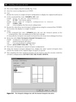
Properties icon from the Standard toolbar and:
prompt Properties dialogue box
respond 1. pick Categorised tab
2. pick Color line – highlights
3. scroll at right of Color line
4. pick Blue – Fig. 2.4
5. Close the Properties dialogue box – top right pick
6. press ESC key
4. The square will be displayed with blue lines
10 Modelling with AutoCAD 2002
Figure 2.4 The Properties dialogue box for the selected square.
modelling with AutoCAD.qxd 17/06/2002 15:37 Page 10
Step 3: arraying the pillar
1. Select the ARRAY icon from the Modify toolbar and:
prompt Array dialogue box
respond 1. Rectangular Array active
2. Rows: 2; Columns: 2
3. Row offset: 50 and Column offset: 50
4. Angle of Array: 0
5. pick Select objects and:
prompt Select objects at the command line
respond window the blue square then right-click
prompt Array dialogue box
respond pick Preview<
and blue square arrayed as expected?
then Array message and pick Accept
2. The blue square will be arrayed in a 2×2 matrix pattern
Step 4: the top
1. Set the elevation to 130 and the thickness to 15
2. Draw a circle, centred on 100,100 with radius of 50
3. Using the pickbox:
a) pick the circle then the Properties icon
b) set the colour to green
Step 5: the 3D viewpoint
1. Menu bar with View-3D Views-SE Isometric
2. The model is displayed in 3D but appears rather ‘cluttered’
Step 6: hiding the model
1. Menu bar with View-Hide model displayed with hidden line removal
2. Menu bar with View-Regen to restore the original model
Step 7: setting another viewpoint
1. At the command line enter VPOINT <R> and:
prompt Specify a new view point or [Rotate]
enter R <R> – the rotate option
prompt Enter angle in XY plane from X axis and enter: 300 <R>
prompt Enter angle from XY plane and enter: –15 <R>
2. Menu bar with View-Hide to ‘see’ the model from below
3. Menu bar with View-Regen to restore the original model
4. Restore the original 3D view with View-3D Views-SE Isometric
Step 8
1. The model should be displayed in 3D at a SE Isometric viewpoint
2. Using the command line, set the elevation to 0 and the thickness to –60
3. Draw a circle with centre at 100,100 and radius 30
4. The circle will be displayed in 3D as a ‘cylinder’
5. Change the colour of the added ‘cylinder’ to magenta
6. As the model is complete, save as C:\MODR2002\EXT-2
Extruded 3D models 11
modelling with AutoCAD.qxd 17/06/2002 15:37 Page 11
Task 1
Use the menu bar with the following menu bar sequences:
a) View-3D Views-SE Isometric
b) View-Hide and note green circle display
c) View-Shade-Flat Shaded and note colour effect and icon
d) View-Shade-3D Wireframe
e) View-Hide and note the green circle display
f) View-Shade-Flat Shaded, Edges On
g) View-Shade-2D Wireframe and note the green circle display
h) View-Regen to ‘restore’ the original model
Task 2
1 Still with the SE Isometric viewpoint displayed
2 Set the elevation to 0 and the thickness to 100
3 With Draw-Rectangle create a rectangle anywhere on the screen
4 With Draw-Ellipse-Center create an ellipse anywhere on the screen
5 Both the rectangle and the ellipse will be drawn without any thickness, although the
thickness was set to 100 in step 2
6 At the command line enter CHANGE <R> and:
prompt Select objects
respond pick any point on the rectangle then right-click
prompt Specify change point or [Properties]
enter P <R> – the Properties option
prompt Enter property to change [Color/Elev/Layer etc
enter T <R> – the thickness option
prompt Specify new thickness <0.00>
enter 100 <R>
prompt Enter property to change
enter <R> – to end command as no other properties to change
7 The rectangle will now be displayed in 3D with a thickness
8 Using the same sequence and entries as step 6, select the ellipse. No thickness will ‘be added’
9 With the CHANGE command, alter the elevation of the ellipse to 50.
Task 3
1 Display a SE Isometric viewpoint and set the elevation and thickness both to 0. Layer
MODEL still current
2 Draw the following objects:
a) polygon with 6 sides, centred on 0,0 and inscribed in a 50 radius circle
b) circle, centre on 0,0 with radius 40
c) polygon with 5 sides, centred on 0,0 and inscribed in a 30 radius circle
3 Set PICKFIRST to 0 then use the CHANGE command to alter the three objects with the
following information:
object elev thickness colour
6 sided polygon 0 50 red
circle 50 80 blue
5 sided polygon 130 30 green
4 Investigate the hide and shade commands and other 3D viewpoints
5 This exercise is now complete. Do not save these additions.
12 Modelling with AutoCAD 2002
modelling with AutoCAD.qxd 17/06/2002 15:37 Page 12
Summary
1 An extruded model is created from an elevation and thickness
2 Extruded models are created ‘as sides’
3 The elevation and thickness values are usually set from the command line
4 The elevation and thickness of objects can be altered with:
a) command line CHANGE with PICKFIRST 0
b) Properties icon with PICKFIRST 1 – dialogue box method
5 Extruded models are viewed in 3D with the 3D Views command which will be discussed
in detail in a later chapter
6 3D models are displayed with AMBIGUITY, i.e. are you looking down from the top or
up from the bottom?
7 The HIDE command is used to display 3D models with hidden line removal. This removes
the AMBIGUITY effect
8 The SHADE command gives useful displays with coloured objects.
Assignment
During the assignments you will frequently meet a character called MACFARAMUS. This
august gentleman was a great architect in ancient times, but sadly most of his works have
not been given the credit they deserve. Your first assignment is to create as a 2
1
⁄2D model,
a famous structure of MACFARAMUS which consists of several traditional geometric
shapes. (All the activity drawings are at the end of the book, starting on page 323.)
Activity 1: Coloured structure of MACFARAMUS
1 Open your 3DSTDA3 template file
2 Using the elevation and thickness method, create the 2
1
⁄
2D model of the structure in ‘plan’
view using the following information:
level shape elev thick colour no size
1 square 0 50 red 1 150 sq
2 circle 50 120 blue 4 R 15 arrayed in R55
3 octagon 170 40 green 1 inscribed in R80
4 semi-circle 210 30 magenta 1 size to suit
3 All relevant data is given in step 2 and in the Activity 1 drawing, but use your discretion
for any sizes not given
4 Setting the grid to 10 and snap to 5 may help
5 Decide for yourself whether to:
a) set the elevation and thickness values then draw the shapes
b) draw the shapes with elevation 0 then change the elevation and thickness values
6 Decide on whether to use the CHANGE or Properties dialogue box, i.e.
a) PICKFIRST 0 – CHANGE at command line
b) PICKFIRST 1 – Properties dialogue box
7 When the model is complete, view at different 3D viewpoints and then hide and shade.
8 Note that at present you will not be able to obtain the two different views on the one
screen (unless you have some prior AutoCAD 3D knowledge).
9 Remember to save the completed model.
Extruded 3D models 13
modelling with AutoCAD.qxd 17/06/2002 15:37 Page 13
The UCS and 3D
coordinates
AutoCAD uses two coordinates systems:
1 the world coordinate system (WCS)
2 the user coordinate system (UCS)
The World Coordinate System (WCS)
All readers should be familiar with the basic 2D coordinate concept of a point described
as P1 (30,40) – Fig. 3.1. Such a point has 30 units in the positive X-direction and 40
units in the positive Y-direction. These ordinates are relative to an XY axes system
with the origin at the point (0,0). This origin is normally positioned at the lower left
corner of the screen and is perfectly satisfactory for 2D draughting but not for 3D
modelling.
Chapter 3
Figure 3.1 2D Coordinate entry with the WCS at the (0,0) origin.
Figure 3.2 3D coordinate input.
modelling with AutoCAD.qxd 17/06/2002 15:37 Page 14
Drawing in 3D requires a third axis (the Z axis) to enable three-dimensional coordinates
to be used. The screen monitor is a flat surface and it is difficult to display a three-axis
coordinate system on it. AutoCAD overcomes this difficulty by using an ICON and this icon
can be moved to different positions on the screen and can be orientated on existing objects.
Figure 3.2 shows the basic idea of how the icon has been constructed. The X and Y axes
are displayed in their correct orientations while the Z axis is pointing outwards towards
the user. The W on the icon indicates that the user is working with the world coordinate
system. The origin is at the point (0,0,0) and is positioned at the lower left corner of the
screen – as it is in 2D. The status bar displays the three coordinates of any point on the
screen, but these figures can be misleading, especially when viewing in 3D. The origin
point can be positioned to suit the model being created – more on this later.
The point P2 (30,40,5) is thus defined as 30 units in the positive X direction, 40 units
in the positive Y direction and 50 units in the positive Z direction. Similarly the point
P3 (–40,–50,–30) has 40 units in the negative X direction, 50 units in the negative Y
direction and 30 units in the negative Z direction.
In the previous chapter, all the extruded models were created with the WCS.
The User Coordinate System (UCS)
The UCS is one of the most important concepts in 3D modelling and all users must be
fully conversant with it. The user coordinate system allows the operator to:
a) set a new UCS origin point
b) move the origin to any point (or object) on the screen
c) align the UCS icon with existing objects
d) align the UCS icon to suit any ‘plane’ on a model
e) rotate the icon about the X, Y and Z axes
f) save UCS ‘positions’
g) recall previously saved UCS settings
Icon display
AutoCAD 2002 allows the user to display the icon as a 2D symbol or as a 3D symbol.
The previous discussion has assumed that the user has the traditional AutoCAD 2D icon
displayed (as Fig. 3.2) but this may not be the icon displayed on your screen. To investi-
gate the UCS icon display:
1 Close all existing drawings
2 Menu bar with File-New and select Start from Scratch-Metric-OK
3 A blank drawing screen will be returned
4 Menu bar with View-Display-UCS Icon and:
a) ensure On active – tick
b) ensure Origin active – tick
c) pick Properties and:
prompt UCS Icon dialogue box
respond 1. UCS icon style: pick 2D and note Preview
2. UCS icon size: set to suit – normally 15–20
3. UCS icon color: set to Suit – Black is default
4. Layout tab icon color: set to suit (Black default)
5. pick OK
5 The icon is displayed as Fig. 3.3(a)
The UCS and 3D coordinates 15
modelling with AutoCAD.qxd 17/06/2002 15:37 Page 15
6 Menu bar with View-3D Views-SE Isometric and the icon will be displayed in 3D as
Fig. 3.3(b)
7 Enter U <R> to restore the original ‘plan’ icon
8 Repeat step 4 and from the UCS Icon dialogue box:
a) set UCS icon style: pick 3D and note Preview
b) ensure Cone active – tick
c) set Line width: 1
d) dialogue box as Fig. 3.4
e) pick OK
9 The icon will be displayed as Fig. 3.4(c) and as Fig. 3.4(d) if a SE Isometric viewpoint
is set
As the user, you must now decide on whether to display the 2D or 3D icon. It is your
preference.
16 Modelling with AutoCAD 2002
Figure 3.3 The 2D and 3D icon display.
Figure 3.4 The UCS Icon dialogue box with the 3D icon set.
modelling with AutoCAD.qxd 17/06/2002 15:37 Page 16
UCS icon exercise
The appearance of the coordinate icon alters depending on:
a) its orientation, i.e. how it is ‘attached’ to objects
b) the viewpoint selected or entered
To investigate the UCS icon display, the following exercise is given as a sequence of
operations which the reader should complete. No drawing is involved and it should be
noted that several of the commands will be new to some readers, all of which will be
explained later. The object of the exercise is to make the reader aware of the ‘versatility’
of the coordinate icon.
1 Close all existing drawings then open your 3DSTDA3 template file. Refer to Fig. 3.5
2 Menu bar with View-Display-UCS icon and:
a) On and Origin both active, i.e. tick
b) pick Properties and activate the UCS icon style
3 The icon will be displayed at the lower left corner of the screen has a W on it, indicating
that it is the WCS icon as fig(a). This is the ‘normal’ default icon.
4 Select the PAN icon from the Standard toolbar or enter PAN <R> at the command line
and:
a) pan the screen upwards and to the right
b) right-click and pick Exit
The UCS and 3D coordinates 17
Figure 3.5 Icon exercise.
modelling with AutoCAD.qxd 17/06/2002 15:37 Page 17