Correcting the effect of temperature on image quality of thermal imaging objectives by wavefront coding technique
Bạn đang xem bản rút gọn của tài liệu. Xem và tải ngay bản đầy đủ của tài liệu tại đây (912.15 KB, 11 trang )
Physics
Correcting the effect of temperature on image quality of thermal imaging
objectives by wavefront coding technique
Nguyen Phuong Nam1, Le Van Nhu2*
1
Institute of Electronics;
Military Techique Academy.
*
Corresponding author:
Received 19 Jul 2022; Revised 10 Aug 2022; Accepted 07 Nov 2022; Published 18 Nov 2022.
DOI: />2
ABSTRACT
The paper has proposed a method for correcting the effect of temperature on the imaging
quality of thermal imaging systems by wavefront coding technology. A cubic phase mask was
added to the aperture diaphragm of the thermal imaging objective to obtain a temperatureinvariant point spread function (PSF). The received images will be of low quality but almost
invariant with the change in temperature. An inverse filter was used to recover high-quality
images over a variable temperature range. To demonstrate the effectiveness of the proposed
method, a thermal imaging objective was used to experiment. The simulation results demonstrate
that the proposed method can effectively eliminate the temperature influence on the image
quality of the thermal imaging objective.
Keywords: Thermal objective; Defocus; Restored algorithm.
1. INTRODUCTION
Thermal imaging objectives are made from infrared materials such as Ge, ZnS, ZnSe,
etc [1, 2]. The thermal refractive index coefficient, thermal expansion coefficient and
photothermal constant of these materials working in the infrared spectral range are
relatively large compared to these parameters of optical materials working in the daytime
spectral region. Therefore, infrared materials used to fabricate thermal imaging
objectives are often quite sensitive to temperature changes [3]. When the temperature
changes, the parameters such as refractive index, thickness, and radius of curvature of
the optical system will change significantly. The resulting change of these parameters
leads to a significant change in the focal length of the thermal imager, the amount of
which is called defocus [4]. This causes a position mismatch between the focal plane and
the sensor plane of the receiver. This results in the image quality of the thermal imaging
objective being degraded. In addition, when the parameters of the thermal imaging
objective are changed, the aberration of the thermal imaging objective will also change
and this also contributes to the change in the image quality of the thermal imager.
However, the amount of defocus shift is a major contributing factor to the image quality
deterioration of the thermal imaging objective. Therefore, a number of solutions have
been proposed to compensate for the change of defocus shift such as the mechanical
compensation method, optical compensation method, electromechanical compensation
method [5]. The purpose of these methods is to place the image of the thermal imaging
optical system in the correct position of the receiver matrix at any temperature value.
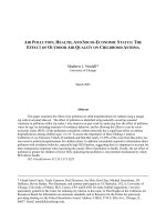
The wavefront coding method was first introduced in 1995 allowing to extend the
depth of field [6-8]. In this method, a wavefront coding component is added to the
conventional optical system in order to obtain an invariant point spread function over a
wide range of depth of field. Figure 1 shows a schematic diagram of a wavefront coding
48
N. P. Nam, L. V. Nhu, “Correcting the effect of temperature … by wavefront coding technique.”
Research
optical system. The wavefront coding component has the function of changing the output
wavefront of the optical system in order to provide a point spread function that is
invariant over a wide range of depth of field compared to the function of traditional
optical systems. Because the point spread function of the wavefront coding optics is
nearly invariant over a wide range of depth of field, a point spread function can be used
to restore sharp images close to the best quality images of conventional optical systems.
Despite the fact that, the wavefront coding technique also has its limitation that the
restored image is affected by noise and impurities.
phase
mark
Restored
images
objective
Images on
receiver
Figure 1. Schematic diagram of wavefront coding method. A component that modifies
the wavefront is incorporated into the conventional optical system.
In this paper, we apply the wavefront coding technique to the thermal imaging
objective to eliminate the influence of temperature on the image quality. In which, an
inverse filter has been applied for image restoring.
2. THEORETICAL BASIS AND PROPOSED METHOD
2.1. Change of parameters of thermal imaging objective with temperature
As the temperature changes, the refractive index of the optical material changes and
can be expressed by expression (1):
n n0 (T T0 )
(1)
where, is the coefficient of refractive index change with temperature, also known as
the thermal refractive index coefficient of the material, n0 is the refractive index at
temperature T0, T is the actual working temperature.
When the temperature changes, the thickness and radius parameters of the thermal
imaging objective will also change and can be expressed by the following expressions:
d d0 [1 (T T0 )]
(2)
r r0 [1 (T T0 )]
(3)
where d0 and r0 are the values of thickness and radius at temperature T0; is the thermal
expansion of the optical material.
In the case of a single lens, the focal length of the lens is determined by the following
expression:
Journal of Military Science and Technology, No.83, 11 - 2022
49
Physics
1
1 1
(n 1)( )
'
f
r1 r2
(4)
By differentiating expression (4), we get the following transformation:
dr dr
df '
1 1
dn( ) (n 1)( 1 2 )
'2
f
r1 r2
r1
r2
(5)
Replace dn=T; dr1=T; and dr2=T in the expression (5):
df '
(
)T
(6)
'
f
n 1
(7)
f ' f ' (
)T
n 1
in which, T=T-T0 is the temperature difference.
As the focal length changes, the wavefront parameter of the defocus shift is as follows:
W20
f '
2
hay
W20
'
2
8( f / #)
(8)
Thus, when the temperature changes, the focal length of the thermal imaging objective
changes, producing a defocus amount that changes the image quality of the thermal imager
objective. If the thermal image objective is composed of many single lenses (multi-element
objective), the change in temperature will lead to a change in the focal length (an amount
of f’) of each lens in the system. That causes the focal length of the whole system to
change. And the amount of defocus as the focal length changes are the sum of the defocus
amounts of the single lens elements in the thermal imaging objective.
2.2. Method
In this paper, we apply wavefront coding technology to the thermal imaging
objective. A cubic mask is introduced into the thermal imaging objective to obtain a
point spread function that is invariant with temperature change. The cubic function has
the following form:
f ( x, y) a( x3 y 3 )
(9)
where a is the mask parameter to control the phase profile.
When the cubic phase mask is applied to the thermal imaging objective, the restored
image will be of much lower quality than that obtained by the conventional thermal imaging
objective at 20 °C. Therefore, an image recovery process needs to be implemented.
The intensity image of the imaging system can be represented by the expression:
𝑔 =𝑜⊗ℎ+𝑛
(10)
where o is the observed object; h is the point spread function; n is noise; the symbol is
the convolution operator.
In the spatial frequency field, expression (10) is represented by [8, 9]:
𝐺 =𝑂×𝐻+𝑁
50
(11)
N. P. Nam, L. V. Nhu, “Correcting the effect of temperature … by wavefront coding technique.”
Research
where G is the Fourier transform of the image, g; O is the Fourier transform of the
image, o; H is the Fourier transform of the point spread function, h.
To perform the analysis of decoding capability of the digitization process, noise is
ignored due to the PSF and h of a wavefront coding optical system with a cubic phase
mask does not change much with focus deviation. In this paper, we propose a solution to
eliminating the influence of temperature on the imaging quality of the optical system. An
inverse filter is used for image restoration over a variable temperature range. The inverse
filter is expressed as follows:
H L _ 20
(12)
F
H C _ 20
where HL_20 is the Fourier transform of the PSF corresponding to the traditional thermal
imaging objective at 20 oC; HC_20 is the Fourier transform of the PSF for the thermal
image objective with wavefront coding technology at 20 oC. At this temperature, the
optical system is optimized and its value is usually around the middle of the temperature
variation.
The Fourier transform of the restored image is shown:
𝑂 =
×𝐺
(13)
Performing the inverse Fourier transform, we get the image o' after processing. This
image is the system recovery image.
3. SIMULATION RESULTS
To test the effectiveness of the proposed method, a thermal imaging optical system is
used with the system parameters at 20 C as follows: input pupil diameter of 20 mm, the
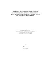
wavelength range of 8 m -12 m. Table 1 shows the structural parameters of a thermal
imaging objective. Figure 2 shows the shape of the thermal imaging objective. The
thermal objective is composed of three individual lenses. These three single objective
lenses are all designed with Ge material.
Table 1. System parameters of the thermal imaging objective.
Obj
Stop
1
2
3
4
5
6
7
Radius
Infinity
Infinity
24.947
32.102
347.093
29.536
240.663
-56.374
Thickness
2
0.5
3.30
8.93
2.50
3.39
3.30
24.326
Glass
Ge
Ge
Ge
Ge
Semi-diameter
11
11
11
11
9.5
9.5
11
11
We now consider the effect of temperature on the quality of the above thermal
imaging objective using the PSF. The size of PSF is 128128 pixels. The lower the PSF
and the larger the size, the more degraded the image quality is. The temperature range
considered is from 0 C to 50 oC. The PSF for the thermal imaging objective at different
temperature values is shown in figure 3. The thermal imaging objective is designed at a
Journal of Military Science and Technology, No.83, 11 - 2022
51
Physics
temperature of 20 oC so the PSF at this temperature is the best. As the temperature values
are further away from the 20 oC temperature value, the lower the PSF becomes and the
larger the size. With a temperature less than 20 oC, the PSF at 0 oC is much lower than
the PSF at 20 oC. With a temperature greater than 20 oC, the higher the temperature, the
lower the PSF and the larger the size. At 50 oC, the PSF is the lowest and the largest size.
Figure 2. Thermal imaging optical system.
(a) 0 C
(c) 20 C
52
(b) 10 C
(d) 30 C
N. P. Nam, L. V. Nhu, “Correcting the effect of temperature … by wavefront coding technique.”
Research
(e) 40 C
(f) 50 C
Figure 3. PSF at different temperatures.
In the simulation, the sensor size is 256x256 pixels. The input image for the imaging
simulation of the optical system is shown in figure 4.
Figure 4. Original image.
Figures 5(a), 5(b), 5(c), 5(d), 5(e) and 5(f) show the obtained images of the optical
system at different temperatures 0 oC, 10 oC, 20 oC, 30 oC, 40 oC and 50 oC,
correspondingly. From figure 5, it can be seen that the image of the optical system at 20 oC
has the best quality. As the temperature decreases or increases compared to the
temperature value of 20 oC, the image quality of the optical system is deteriorated. As
the temperature decreases, the image quality of the optical system at 0 oC is of the
lowest. While the temperature increases, the image quality of that at 50 oC is the lowest,
too. In particular, the image quality of the optical system at 50 oC is the worst in all
temperature values. This is consistent with the evaluations of the PSF mentioned above.
Table 2. Parameters of the thermal imaging objective.
Obj
Stop
1
2
3
4
5
6
7
Radius
Cubic phase mask
Infinity
24.947
32.102
347.093
29.536
240.663
-56.374
Thickness
2
0.5
3.30
8.93
2.50
3.39
3.30
24.326
Journal of Military Science and Technology, No.83, 11 - 2022
Glass
Ge
Ge
Ge
Ge
Semi-diameter
11
11
11
11
9.5
9.5
11
11
53
Physics
Next, we apply the wavefront coding technique to the thermal imaging objective. A
cubic phase mask is added to the pupil of the thermal imaging objective with the
parameters shown in table 2.
(a) 0 C
(c) 20 C
(b) 10 C
(d) 30 C
(e) 40 C
(f) 50 C
Figure 5. Obtained images of the optical system at different temperature values.
In order to obtain good image quality, the phase mask parameters need to be optimized
so that the MTF function is invariant to the change of temperature in the range from 0 C
54
N. P. Nam, L. V. Nhu, “Correcting the effect of temperature … by wavefront coding technique.”
Research
to 50 C. The optimized cubic phase mask equation leads to the invariant point spread
function over the temperature range determined in Zemax software as follows:
f ( x, y) 4*106 ( x3 y3 )
(a) 0 C
(c) 20 C
(e) 40 C
(14)
(b) 10 C
(d) 30 C
(f) 50 C
Figure 6. PSF at different temperatures of the proposed m.
Figure 6 shows the PSF of a thermal imaging objective with a cubic phase mask at
different temperatures, respectively. The PSF at 0 oC, 10 oC, 20 oC, 30 oC, 40 oC and 50 oC
are shown in figure 6(a), figure 6(b), figure 6(c), figure 6(d), figure 6(e) and figure 6(f),
respectively. Figure 6 shows that the PSF of the thermal imaging objective is nearly
invariant with the change of temperature. However, the PSF value is relatively low and
Journal of Military Science and Technology, No.83, 11 - 2022
55
Physics
the size is enlarged. This means that the resulting image of the thermal imaging objective
with the cubic phase mask will be blurred but almost invariant to the temperature
change. These PSFs are nearly identical, so it is possible to use a single PSF function at
one location to recover over the entire temperature range.
(a) 0 C
(b) 10 C
(c) 20 C
(d) 30 C
(e) 40 C
(f) 50 C
Figure 7. Obtained images of the optical system at different temperature values.
The images of the thermal imaging objective with the cubic phase mask at 0 oC, 10 oC,
20 oC, 30 oC, 40 oC, and 50 oC are shown in figures 7(a), 7(b), 7(c), 7(d), 7(e) and 7(f),
respectively. From figure 7, it can be seen that the image quality of the thermal imaging
objective with the cubic phase mask is almost invariant with the change of temperature.
However, the received image is relatively blurry. Therefore, an image processing method
needs to be deployed to obtain sharp image quality.
56
N. P. Nam, L. V. Nhu, “Correcting the effect of temperature … by wavefront coding technique.”
Research
(a) 0 C
(c) 20 C
(b) 10 C
(d) 30 C
(e) 40 C
(f) 50 C
Figure 8. Obtained images of the optical system at different temperature values.
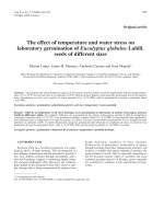
Figure 8 shows the restored image obtained from a thermal imaging objective with a
cubic phase mask at temperature values of 0 oC, 10 oC, 20 oC, 30 oC, 40 oC, 50 oC using the
inverse filter in formula (12). From figure 8, it is clear that the restored image quality of the
thermal imaging objective with the cubic phase mask is sharp and almost invariant to
temperature changes. However, the restored image at values further away from the 20 oC
temperature showed some impurities. Due to this, PSFs at these values are different
Journal of Military Science and Technology, No.83, 11 - 2022
57
Physics
from the PSF at 20 C. This proves that the proposed method can eliminate the influence
of temperature changes on the image quality of the thermal imaging objective.
4. CONCLUSIONS
In this paper, we successfully propose a solution to apply wavefront coding
technology to thermal image objectives in order to eliminate the effect of temperature
change on image quality. A thermal imaging objective was chosen as an example. A
cubic phase mask was added to the thermal imaging objective to obtain a point spread
function that is invariant to temperature variation. The inverse filter has been designed
for image restoration. The image simulation results have demonstrated that the proposed
method can eliminate the influence of temperature changes on the image quality of the
thermal imaging objective.
REFERENCES
[1]. T.H. Jamieson, “Thermal effects in optical systems,” Opt. Eng, 20, pp.156, (1981).
[2]. D.S. Grey, “Athermalization of optical systems,” J. Opt. Soc. Am, 38, pp. 542, (1948).
[3]. B. Feng, Z. Shi, Y. Zhao, H. Liu, L. Liu, “A wide-FoV athermalized infrared imaging
system with a two-element lens,” Infrared Physics & Technology, 87, pp. 11, (2017).
[4]. Q. J. Gao, J. Wang, Q. Sun, “Design of a compact athermalized infrared seeker,”
Optoelectronics Letters, 13, pp. 287, (2017).
[5]. E. R. Dowski, and W. T. Cathey, “Extended depth of field through wave-front coding,”
Appl. Opt, 34, pp. 1859–1866, (1995).
[6]. M. Demennikov, and A. R. Harvey, “Image artifacts in hybrid imaging systems with a cubic
phase mask”, Opt. Express, 18, pp. 8207, (2010).
[7]. M. Demenikov, and A. R. Harvey, “Parametric blind-deconvolution algorithm to remove
image artifacts in hybrid imaging systems,” Opt. Express, 18, pp. 18035, (2010).
[8]. J. Sheng, H. Cai, Y. Wang, X. Chen and Y. Xu, “Improved Exponential Phase Mask for
Generating Defocus Invariance of Wavefront Coding Systems,” Appl. Sci, 12, pp. 5290,
(2022).
[9]. V. Le, Z. Fan, S. Chen, D. D. Quoc, “Optimization of wavefront coding imaging system
based on the phase transfer function,” Optik, 127, pp. 1148, (2016).
TÓM TẮT
Hiệu chỉnh ảnh hưởng nhiệt độ đến chất lượng ảnh vật kính ảnh nhiệt
bằng cơng nghệ mã hố mặt sóng
Bài báo đã đề xuất một giải pháp cho hiệu chỉnh ảnh hưởng của nhiệt độ đến
chất lượng tạo ảnh của hệ thống ảnh nhiệt bằng công nghệ mã hố mặt sóng. Một
mặt nạ pha bậc ba đã được thêm vào diafram khẩu độ của vật kính ảnh nhiệt để
thu được hàm nhoè điểm bất biến với nhiệt độ. Ảnh nhận được sẽ có chất lượng
thấp nhưng gần như bất biến với sự thay đổi của nhiệt độ. Một phin lọc nghịch đảo
đã được sử dụng cho khôi phục ảnh chất lượng cao trên một khoảng nhiệt đột thay
đổi. Để chứng minh hiệu quả của phương pháp đề xuất, một vật kính ảnh nhiệt đã
được sử dụng làm ví dụ. Kết quả mơ phỏng chứng minh rằng, phương pháp đề
xuất có thể loại bỏ hiệu quả ảnh hưởng nhiệt độ đến chất lượng vật kính ảnh nhiệt.
Từ khố: Vật kính ảnh nhiệt; Lệch tiêu; Thuật tốn khơi phục ảnh.
58
N. P. Nam, L. V. Nhu, “Correcting the effect of temperature … by wavefront coding technique.”