Prediction of material thickness on dome of geodesic wound orthotropic composite vessel
Bạn đang xem bản rút gọn của tài liệu. Xem và tải ngay bản đầy đủ của tài liệu tại đây (591.03 KB, 8 trang )
Research
Prediction of material thickness on dome
of geodesic wound orthotropic composite vessel
Dinh Van Hien*, Tran Ngoc Thanh
Institute of Missile, Academy of Military Science and Technology;
*
Corresponding author:
Received 2 Sep 2022; Revised 28 Oct 2022; Accepted 7 Nov 2022; Published 18 Nov 2022.
DOI: />
ABSTRACT
Orthotropic composite pressure vessels are designed based on considering the role of a matrix
in the force balance of the structure and its leakage due to matrix failure. To be more specific, the
stress and strain states of the shell are considered simultaneously in both longitudinal and
transverse directions of the fiber. Due to such a loaded condition, the laminate thickness
prediction of the shell does not use the maximum stress criterion as with the traditional
monotropic composite vessels but rather the multi-axial failure criterion of the composite
material. With the developed and published platforms on the design of the dome profile of the
composite vessel, this paper focuses on predicting the laminate thickness of the geodesic wound
dome of the pressure vessel according to Tsai-Wu failure criteria, simultaneously the material
thickness distribution on the dome as a basis for determining structural parameters of the vessels.
Keywords: Laminate thickness; Composite pressure vessel; Orthotropic composite; Geodesic winding.
1. INTRODUCTION
The design and manufacture of the composite pressure shell of revolution have been
developed over the years. For a cylindrical composite vessel with two domes, the structural
design problem revolves around two main issues: 1- determining the dome profile to
ensure a balanced shape and 2- finding the layer thickness to ensure durability, thereby
serving as a premise for determining the winding processing parameters. According to the
mathematical description of the fiber trajectory, there are two winding types: geodesic
winding and non-geodesic winding, where the geodesic winding is a technique of
spreading the fiber on the shell surface, which under the action of fiber tension, the
transverse force acting on the fiber is zero, i.e., the fiber has no tendency to slip.
Normally, to determine the dome profile, it is assumed that the composite material
is monotropic. When loaded, the material is subjected to tensile stress that is uniformly
distributed along the fiber axis and equally in all fibers. This approach is called the
netting theory. However, in practice, continuous fiber-reinforced composites always
exhibit orthotropy. In order to get closer to the actual behavior of the material, the
continuum theory (lamination theory) has been developed to determine the dome
profile, typically as reported by Liang et al. (2002) [1], Vasiliev (2003) [2], Zu et al.
(2010) [3], Hien and Thanh (2021) [4] for geodesic and non-geodesic wound
composite pressure vessels.
To estimate the laminate thickness, a suitable strength criterion should be used. Some
biaxial failure criteria for orthotropic lamina that have been studied are 1- the maximum
stress criterion; 2- the maximum strain criterion; 3- Tsai–Hill failure criterion; and 4Tsai–Wu failure criterion. In fact, the failure of a composite pressure vessel generally
includes two main steps: firstly, cracks appear in the matrix, and then the pressure is
Journal of Military Science and Technology, No.83, 11 - 2022
95
Mechanics & Mechanical engineering
taken up by the fibers until they fail [5]. Matrix failure is a serious issue for the safety of
a pressure vessel. However, no interaction exists between the failure modes in the
maximum stress and strain criterion. Meanwhile, there are certainly some faults in the
orthotropic lamina with the Tsai–Hill failure criterion [6]. To avoid both tensile failures
transverse to fibers and shear failure along fibers, the design against the failure is
determined by employing the Tsai–Wu tensor failure criterion. This failure theory is a
relatively new multi-axial strength theory. Specific merits of the Tsai– Wu failure
criterion include: 1- invariance under rotation or redefinition of coordinates; 2transformation via known tensor transformation laws; and 3- symmetry properties akin
to those of stiffness and compliances [6]. Tsai-Wu criterion has been widely applied to
predict the failure of composite pressure vessels by many authors.
To apply new theories to the design of composite shells of revolution, in this paper,
we focus on developing the Tsai-Wu failure criteria to predict the composite layer
thickness of the dome of the pressure vessel. In addition, the prediction of material
thickness distribution on the dome is also developed in order to approach the actual
distribution to serve the design problem accurately.
2. THEORETICAL BACKGROUND
2.1. Review of building geodesic dome profile
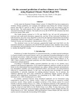
2.1.1. Geometry and physics of filament wound dome
O
Figure 1. The geometry of a dome shell Figure 2. Stress-strain components
of revolution.
in shell element.
Consider a dome surface of revolution S(z,) = [z, r(z)cos, r(z)sin]T with z, the axial
coordinate, , the angular coordinate and r, the radial coordinate as described in Fig. 1.
Some main characteristic parameters are as follows:
- R and rp are the radial radii of the dome equator and the polar hole;
- is the winding angle (angle between the fiber and meridian of the dome);
- p and q are the internal pressure and the force on length unit at the polar hole, q =
p.rp/2 for the closed polar hole and q = 0 for the opened polar hole.
2.1.2. Geodesic winding condition
Geodesic winding involves having windings go along the shortest distance between
two points on the winding surface to ensure structural stability, that is, no slipping and
no bending between the filaments and the winding surface. The geodesic condition is
satisfied as follows [1-4]:
r.sin rp
(1)
96
D. V. Hien, T. N. Thanh, “Prediction of material thickness … orthotropic composite vessel.”
Research
2.1.3. Stress components and optimum condition of dome profile
- Stresses in meridian and parallel directions based on membrane theory [4, 7]:
rp2
1 C p . 2
r
rp2
N
p.r . 1 r '2
r .r ''
2
1
C
.
p
2
h
2.h
r 2
1 r '
p.r . 1 r '2
h
2.h
N
(2)
(3)
where the subscripts and denote the meridional and parallel direction of the dome,
respectively; N is the dimensionless force resultants; h is the material thickness;
r , rp , z , h are the dimensionless parameters r r / R , rp rp / R , z z / R , h h / R ;
r ' and r '' are the first and second derivatives of r with respect to z ; Cp = 0 or 1 is for
the dome with the closed or opened polar hole, respectively.
- Stress components based on classical laminate theory: The description of stress
components in the composite element of the shell is as in Fig. 2. Since the shell and
applied load are axially symmetric, the shear stresses and strains in the meridian and
parallel direction must be equal to zero. Thus, we have the following relations [8]:
1.cos2 2 .sin 2 12 .sin 2
(4)
1.sin 2 .cos 12 .sin 2
(5)
2
2
where subscripts 1 and 2 denote the longitudinal and transverse direction of the filament
fibers; and denote normal and shear stresses.
2.1.4. Equations of geodesic dome profile
- Governing equation of geodesic dome profile: Based on the stress balance, the
condition of the equal shell strains, and the geodesic condition (1), the governing
equation of the geodesic dome profile is determined as follows [4]:
1 k .r 2 (1 k ).rp2
2.r 2
2
r '' . 2
. 1 r '
(6)
2
2
2
r
r
(
k
1).
r
r
C
.
r
p
p p
E (1 v21 )
where k 2
is the anisotropic parameter of the composite material; E and v are
E1 (1 v12 )
moduli, and Poisson’s ratios satisfy the following relationship E1.v12 E2 .v21 .
- Fitting equation of dome profile: The dome meridian specified by equation (6) often has
an infection point where the direction of the curvature changes [7]. To obtain the full dome
profile of the pressure vessel, we need a fitting equation having the following form [7]:
z R .sin z 2 r R .cos r
1f
f
f
1f
f
f
2 1/2
f acos (1 r ) z z
f
2
R12f
(7)
where the subscripts f denotes the fitting point; R1 is the dimensionless meridional
radius; is the angle between the radial radius and the parallel radius.
Journal of Military Science and Technology, No.83, 11 - 2022
97
Mechanics & Mechanical engineering
2.2. Composite laminate thickness on the dome
2.2.1. Tsai–Wu failure criterion
As analyzed in the section “Introduction”, in this study, the Tsai-Wu failure criterion
will be used to predict the laminate thickness of the dome. The expanded form of the
Tsai-Wu criteria is as follows [9]:
2
F1.1 F2 .2 2.F12 .1.2 F11.12 F22 .22 F6 .12 F66 .12
1
(8)
where 1 and 2 are derived by the relations (4) and (5), which are expressed as
equations (9) and (10); 12 is zero based on the optimized condition [4]; Fi and Fij are the
strength parameters determined by the relations (11).
- Expressions for 1 and 2 :
1
2
in which m
m.N n.N
(9)
h
m.N n.N
(10)
h
cos 2
sin 2
n
and
.
sin 2 cos 2
sin 2 cos 2
- Expressions for Fi and Fij:
1
1
1
1
1
1
F1 T C , F2 T C , F12 .
,
T
C
2 X 1 . X 1 . X 2T . X 2C
X1 X1
X2 X2
1
1
1
1
1
F11 T C , F22 T C , F6 T C , F66 T C
X1 .X1
X 2 .X 2
X 12 . X 12
X 12 X 12
(11)
in which X 1T , X 1C , X 2T and X 2C stand for the tensile and compressive strengths of the
unidirectional layer in the longitudinal ad transverse directions of the filament; X 12T and X 12C
are the positive and negative shear strength of laminate (the solver usually considers
X12T X12C ).
2.2.2. Objective function of thickness at the equator of the dome
By substituting equations (9) and (10) into the relation (8) and taking the equal sign,
as well as referring to equations (2) and (3), we get the following one:
f (h ) a1h 2 b1h c1 0
(12)
in which a1 = 1; b1 and c1 are coefficients determined as the below ones.
b1 F1. m.N n.N F2 . m.N n.N
c1 2.F12 . m.N n.N m.N n.N F11. m.N n.N
F22 . m.N n.N
2
(13)
2
(14)
Equation (12) is the second-order equation having the product of a1 and c1 to be
98
D. V. Hien, T. N. Thanh, “Prediction of material thickness … orthotropic composite vessel.”
Research
negative. Thus, it always exists a positive root corresponds to the material thickness h .
From the relations (13) and (14), we also see that b1 and c1 depend on the dimensionless
radial distance r and the winding angle . It means that b1 and c1 depend on the
dimensionless axial coordinate z . Therefore, for a determined dome shape, at an
arbitrary point assigned on the dome, we will receive a value h ( z ) evaluated by solving
equation (12).
Now, to determine the material thickness at the equator and thickness distribution on the
dome, we need two assumptions (1)- the number of all the fibers crossing any plane is
constant; and (2)- the fiber volume fraction is maintained consistently. Since those, we have:
cos eq
h h (z) heq .
(15)
r (z).cos (z)
where heq is the dimensionless material thickness at the equator.
As above-analyzed, for each determined thickness of h ( z ) , we will derive a certain
value of heq from equation (15); Thus, the final thickness at the equator will be the
maximum of all values of heq expressed as follows:
r ( z ).cos (z)
heq max max h ( z ).
(16)
0 z z p
cos eq
2.2.3. Prediction of thickness on the dome
Equation (16) can fairly describe the shell thickness in the distance
r2 w rp 2w r 1 [10], where w is the dimensionless width of the fiber tape,
w w / R (w- The tape width). In the vicinity of the polar hole, rp r r2 w , we should
use a smooth approximation in the form of a third-order polynomial as follows [10]:
ha ( z ) a2 z 3 b2 z 2 c2 z d2
(17)
where a2, b2, c2, and d2 are coefficients determined by the following conditions:
- The function h( z ) (including ha ( z ) ) is continuous and has a continuous derivative
at (r2 w , z2 w ) , i.e.,
h (z2 w ) ha (z2 w )
(18)
h '(z2 w ) ha '(z2 w )
(19)
- The material volume calculated by equations (15) and (17) for rp r r2 w is
similar, i.e.,
zp
zp
2 r ( z ).h ( z ). 1 r '( z ) dz 2 r ( z ).ha ( z ). 1 r '( z ) 2 dz
2
z2 w
(20)
z2 w
- At the polar hole, the material thickness, h p , is given, i.e.,
ha (z p ) hp
Journal of Military Science and Technology, No.83, 11 - 2022
(21)
99
Mechanics & Mechanical engineering
According to Vasiliev [2], the thickness, h p should be chosen in accordance with a
particular process. For free winding with fiber tapes uniformly distributed over the shell
equator without overlap, hp 2heq ; in case of restriction induced by the polar boss, h p
depends on the tape width and can change from 5heq up to 10heq . The above four
expressions are enough to find coefficients a2, b2, c2, and d2.
2.3. Geometric constraints
To solve equations (6) and (7) for determining the dome profile and equations (12),
(15), and (16) for obtaining the material thickness at the equator, we must have some
geometric constraints as follows:
- Continuity condition: At the equator ( z 0 ), r 1 and r ' 0 ; and at the polar
point ( z z p ), r rp ;
- Convexity condition: For 0 z z p , r '' 0 ;
- Side condition: 0 r 1 .
3. RESULTS AND DISCUSSION
In this section, we will give some calculation results from using theoretical formulas
in the section 2 for three common composite materials having mechanical properties, as
in table 1.
Table 1. Mechanical properties of some unidirectional composite materials [8].
Properties
Glass/ Carbon/ Aramid/
epoxy
epoxy
epoxy
Longitudinal modulus, E1 (GPa)
60
140
95
Transverse modulus, E2 (GPa)
13
11
5.1
Poison’s ratio, v21
0.3
0.27
0.34
T
1800
2000
2500
Longitudinal tensile strength, X 1 (MPa)
1200
300
Longitudinal compressive strength, X 1C (MPa) 650
Transverse tensile strength, X 2T (MPa)
40
50
30
Transverse compressive strength, X 2C (MPa)
90
170
130
50
70
30
In-plane shear strength, X 12 (MPa)
Anisotropic parameter, k
0.265
0.098
0.071
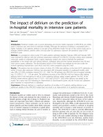
Fig. 3. shows the dome profiles corresponding to three composite materials and the
polar radius, rp 0.2 . It can be found that the bigger the parameter, k, the higher the dome
height. The dome profiles designed for two composite materials, carbon/epoxy and
aramid/epoxy, are almost similar. Fig. 4. shows the effect of the polar radius, rp on the
material thickness at the equator, heq max . It is easy to see that the increase in the polar
radius, rp , causes the material thickness at the equator to increase, the rate of thickness
increase is greater when increasing the polar radius, rp . Due to the influence of the
100
D. V. Hien, T. N. Thanh, “Prediction of material thickness … orthotropic composite vessel.”
Research
strength parameters of the materials, the thickness at the equator of the aramid/epoxy shell
is the smallest, followed by the carbon/epoxy shell and finally the glass/epoxy shell.
Figure 3. Dome profiles corresponding to three
composite materials and rp 0.2 .
Figure 4. Effect of rp on heq max
with p = 10 MPa and w 0.1 .
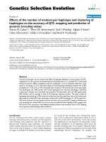
Figure 5. Predicted material thickness on the dome
(material: glass/epoxy, rp 0.2 and hp 5heq ).
Prediction of the distribution of the material thickness on the dome for the
glass/epoxy material, the polar radius, rp 0.2 and the material thickness at the polar
hole, hp 5heq , is shown in Fig. 5. It can be observed that the material thickness
distribution predicted from equation (15) – dashed line, is not realistic due to slipping,
realignment, roving separation of the fiber tows, and material consolidation in the
process of winding and curing. The material thickness predicted by using equation (17) –
solid line, seems more realistic. This has certain significance in developing composite
pressure vessels using the above method and incorporating finite element analysis.
Journal of Military Science and Technology, No.83, 11 - 2022
101
Mechanics & Mechanical engineering
4. CONCLUSIONS
Continuum theory (lamination theory) and Tsai-Wu’s multi-axial failure criterion of
the composite material were utilized in the calculation of structural parameters of the
geodesic wound composite pressure vessel, in which, the problem of determining the
laminate thickness and predicting the material thickness on the dome were applied in this
study. The current study is purely theoretical, but it is useful for the analysis, design, and
determination of actual winding processing parameters of the composite pressure vessel.
REFERENCES
[1]. C. C. Liang et al., “Optimum design of dome contour for filament-wound composite
pressure vessels based on a shape factor”, Composite Structures 58, (2002).
[2]. V. V. Vasiliev et al., “New generation of filament-wound composite pressure vessels for
commercial applications”, Composite Structures 62, (2003).
[3]. L. Zu et al., “Design of filament–wound domes based on continuum theory and nongeodesic roving trajectories”, Composites: Part A 41, (2010).
[4]. Đinh Văn Hiến và Trần Ngọc Thanh, “Biên dạng đáy vỏ trụ composite dị hướng nhận được
bằng phương pháp quấn trắc địa”, Hội nghị KH toàn quốc về CHVR lần thứ XV, (2021),
(in Vietnamese).
[5]. J. S. Park et al., “Analysis of filament wound composite structures considering the change of
winding angles through the thickness direction”. Composite Structures 55 (1), (2002).
[6]. R. M. Jones, “Mechanics of composite materials”, McGRAW-Hill Co, (1975).
[7]. Dinh Van Hien et al., “Design of planar wound composite vessel based on preventing
slippage tendency of fibers”, Composite Structures 254, (2020).
[8]. V. V. Vasiliev and E. V. Morozov, “Advanced mechanics of composite
materials”, UK: Elsevier Ltd, (2007).
[9]. S. W. Tsai and E. M. Wu, “A general theory of strength for anisotropic materials”, J
Compos Mater 5(1), (1971).
[10].A. A. Krikanov, “Refined thickness of filament wound shells”, Science and Engineering of
Composite Materials 10 (4), (2002).
TÓM TẮT
Dự báo chiều dày vật liệu trên đáy của bình áp lực
composite dị hướng được quấn trắc địa
Bình áp lực composite được thiết kế dựa trên việc xem xét vai trò của nền đến
cân bằng lực của kết cấu và rò rỉ của bình do phá hủy của nền, cụ thể là trạng thái
ứng suất và biến dạng của vỏ được xét đồng thời theo cả phương dọc và ngang sợi.
Do điều kiện tải như vậy, việc dự báo chiều dày lớp composite của vỏ khơng dùng
tiêu chuẩn ứng suất chính lớn nhất như với bình composite đơn hướng truyền thống
mà cần dùng tiêu chuẩn phá hủy đa trục của vật liệu composite. Với các nền tảng
đã phát triển và công bố về thiết kế biên dạng đáy vỏ bình áp lực compsite, bài báo
này trọng tâm vào dự báo chiều dày lớp vỏ composite trên đáy của bình áp lực
được quấn trắc địa theo tiêu chuẩn phá hủy Tsai-Wu, đồng thời tiên đoán phân bố
chiều dày vật liệu trên đáy để làm cơ sở cho xác định các tham số kết cấu của bình.
Từ khóa: Chiều dày lớp composite; Bình áp lực composite; Composite dị hướng; Quấn trắc địa.
102
D. V. Hien, T. N. Thanh, “Prediction of material thickness … orthotropic composite vessel.”