Meso/microporous MOF@graphene oxide composite aerogels prepared by generic supercritical CO2 technology
Bạn đang xem bản rút gọn của tài liệu. Xem và tải ngay bản đầy đủ của tài liệu tại đây (8.09 MB, 10 trang )
Microporous and Mesoporous Materials 335 (2022) 111825
Contents lists available at ScienceDirect
Microporous and Mesoporous Materials
journal homepage: www.elsevier.com/locate/micromeso
Meso/microporous MOF@graphene oxide composite aerogels prepared by
generic supercritical CO2 technology
´s , Albert Rosado , Julio Fraile , Ana M. Lo
´pez-Periago , Jos´e Giner Planas **,
Alejandro Borra
***
*
´n Domingo
Amirali Yazdi , Concepcio
Instituto de Ciencia de Materiales de Barcelona, ICMAB-CSIC, Campus UAB s/n, 08193, Barcelona, Spain
A R T I C L E I N F O
A B S T R A C T
Keywords:
Supercritical CO2
MOF
Graphene
Composites
Hierarchical porosity
The increasing complexity in composition and structure of modern porous nanocomposite materials requires the
development of advanced technologies that allow the simultaneous treatment of dissimilar compounds, not only
with unlike composition but also involving different classes of pores, e.g., micro and mesopores. This work shows
that supercritical CO2 (scCO2) technology can be used as generic processing aid to obtain composites involving
non-reduced graphene oxide (GO) and metal organic frameworks (MOFs) in the form of aerogels with hierar
chical porosity. Hybrid aerogels are formed by either depositing (ex situ) or growing (in situ) MOF nanocrystals
onto the surface of 2D GO nanosheets. The archetypal hydrophilic HKUST-1 and UiO-66 and hydrophobic ZIF-8
microporous MOFs are chosen to exemplify the method possibilities. The ex situ route was adequate to prepare
hydrophilic MOFs@GO homogeneous composites, while the in situ approach must be used to prepare hydro
phobic MOFs@GO aerogels. Moreover, the scCO2 methodology should be adjusted for each studied MOF in
regard of the organic solvent used to disperse the nanoentities constituting the composite. The end-products are
obtained in the form of aerogels mimicking the shape of the recipient in which they are contained. The products
are characterized in regard of structure by X-ray diffraction, textural properties by low temperature N2
adsorption/desorption and morphology by electronic microscopy.
1. Introduction
industrial advanced fronts, including supercapacitors, batteries, solar
and fuel cells, building and clothing materials, biomaterials, etc [4]. All
the described methods for constructing graphene-based aerogels start
with graphene oxide (GO), precursor involving a large amount of
oxygenated functionalities (mainly carboxylic acid, epoxy and hydrox
yl) that makes it easily dispersible in water and other polar solvents [5].
As mentioned, the formation of a gel-derived intermediate is required
previous to the drying process, typically induced by a hydro/
solvothermal treatment or supercritical drying at the solvent critical
point. In either case, a concomitant reduction of GO to rGO (material
similar to graphene) occurs due to high temperature processing [6]. The
only viable alternative to obtain stable aerogels based on GO as a
nanometric building unit has been demonstrated to be the use of su
percritical CO2 (scCO2) [7]. In this route, the solvent in the gel is
exchanged by CO2 that is further eliminated at relatively low tempera
ture, thus, avoiding the reduction of GO to rGO. It is important to
The formation of three-dimensional (3D) large bodies is often
imperative for constructing functional devices based on nanoentities. To
this effect, aerogels (or xerogels), dried gels with an extraordinary void
volume, stand out for their multiple applications [1]. Aerogels are highly
porous materials with a continuously interconnected meso/
macroporous structure and large surface area, which are built by small
particles that self-assembly into low-density gels. These gels are then
dried in a controlled way to retain most of their original volume occu
pied by the solvent. Drying stresses, attributed to capillary phenomena
and differential strain, can be avoided by using supercritical fluid or
freeze drying technology to eliminate the liquid from the gel [2].
Development of this outstanding scientific area started with silica aer
ogels [3], although graphene aerogels are decidedly popular materials
nowadays, since they have found tremendous potential across several
* Corresponding author.
** Corresponding author.
*** Corresponding author.
E-mail address: (C. Domingo).
/>Received 28 January 2022; Received in revised form 8 March 2022; Accepted 9 March 2022
Available online 16 March 2022
1387-1811/© 2022 The Authors. Published by Elsevier Inc. This is an open access article under the CC BY license ( />
A. Borr´
as et al.
Microporous and Mesoporous Materials 335 (2022) 111825
distinguish between supercritical CO2 and supercritical alcohol drying,
the latter resulting in hydrophobic rGO aerogels due to the high tem
perature required to reach the supercritical conditions of the alcohol. GO
aerogels dried using scCO2 are hydrophilic, maintaining a considerable
amount of oxygenated functionalities, which gives to them the possi
bility to strongly interact with other materials [8].
Graphene and GO are considered revolutionary materials, and the
range of applications of their aerogel forms is currently under extensive
research, particularly for the creation of composite products [9,10].
These aerogels are constituted by a network of tinny 2D flakes, with
huge pore volume and remarkable surface area, performing as proper
host matrixes into which guest nanoparticles (NPs) can be trapped to
prepare novel composite materials with tuned properties. The functional
groups located on the basal plane of GO not only facilitate the dispersion
and exfoliation of GO in aqueous and polar solutions via simple soni
cation, but could also act as structural templates for the nucleation,
anchoring and growth of different nanomaterials [11]. Simultaneously
to the development of graphene meso/macroporus aerogels, remarkable
progress on microporous materials has been achieved in the last decade,
essentially devoted to the development of metal–organic frameworks
(MOFs), which can be easily precipitated as NPs [12,13]. MOFs are used
in applications of gas adsorption and separation, catalysis, drug de
livery, membranes and so on [14,15]. Particularly, the synergistic
combination and the hierarchical porosity attained by combining GO
aerogel and MOF NPs in a composite is expected to expand the range of
applications of both materials [16]. There are already few reviews
focusing in the development of MOF@GO (or MOF@rGO) multifunc
tional materials [17,18], although there are only few examples reported
in the literature that involves the fabrication of this type of composites in
the form of an aerogel, typically synthetized by using solvothermal re
action and/or freeze-drying methods [19–21]. It is important to note
that in all the described end products, the aerogel was structured around
fully reduced rGO, in which the oxygenated functionalities were no
longer present [22–24].
The expansion to commercial sustainable production of
MOF@graphene-based composite materials has been somehow hin
dered by the difficulties encountered for developing a generic environ
mental and low temperature method for the synthesis of such products,
involving dissimilar inorganic-organic components, molded as 3D ob
jects. The choice of the synthetic strategy would influence the final
material structure and homogeneity, as well as the properties [25]. To
circumvent this drawback, the gelling and drying low-temperature
scCO2 technique, developed recently in our laboratories [7,26], is here
extended as a simple and general synthetic approach for the ex situ and in
situ formation of composites with diverse MOF NPs in the form of
monolithic aerogels. Particularly, the well-known hydrophilic HKUST-1
and UiO-66 and the hydrophobic ZIF-8 were chosen to exemplify the
method possibilities. These three materials are currently considered
archetypal microporous MOFs with benchmark properties in one or
more applications, all related with adsorption [27]. Due to the hydro
philic character of GO, this work shows that the methodological
approach should be adjusted for each studied MOF used to make the
composite. Hence, the ex situ approach was adequate to prepare hy
drophilic MOFs@GO composites with well-dispersed NPs, while the in
situ approach must be used to prepare hydrophobic MOFs@GO products.
Characterization of the obtained aerogels was performed by X-ray
diffraction for structural elucidation, N2 physical adsorption at low
temperature to acquire adsorption/desorption data for the determina
tion of the specific surface area, and scanning electron microscopy for
the morphological analysis.
(BTC), zirconium(IV) oxychloride (ZrOC12⋅8H2O), zinc(II) acetylaceto
nate hydrate (Zn(acac)2⋅xH2O), copper(II) nitrate trihydrate (Cu
(NO3)2⋅3H2O), sodium acetate (CH3COONa), acetic acid (AA), hydro
chloric acid (HCl), dimethylformamide (DMF), ethyl acetate (EA),
ethanol (EtOH), methanol (MeOH), poly(vinylpyrrolidone) (PVP, mo
lecular weight 10,000) were purchased from Sigma Merck-Aldrich.
Graphene oxide (GO) sheets (ca. 10 μm lateral dimensions) were pur
chased from Graphenea Inc., supplied as a dispersion in water with a
concentration of 4 mgmL− 1 that was transformed to a long-term stable
colloidal suspension of GO in EtOH with similar concentration by
following a multi-step water-to-ethanol exchange procedure described
elsewhere [7]. Compressed CO2 (99.95 wt%) was supplied by Carburos
´licos S.A.
Meta
2.2. Methods
2.2.1. Synthesis of MOF particles
HKUST-1 microparticles were precipitated by using a classical
synthetic procedure described elsewhere [28], which involves the
separate dissolution of Cu(NO3)2⋅3H2O (0.87 g) and BTC (0.22 g) re
agents in 10 mL of deionized H2O and EtOH, respectively. The metal
solution was then added to the vial containing the ligand solution,
together with 1 mL of DMF. HKUST-1 nanoparticles were synthetized
following a reported method that uses sodium acetate as a capping agent
[29]. In short, 0.5 g of BTC and 1.04 g of Cu(NO3)2⋅3H2O were dissolved
separately in 12 mL of a mixture of DMF:EtOH:H2O with a v/v ratio of
1:1:1. Both solutions were mixed in a vial, together with 1.63 g of so
dium acetate. For both systems, HKUST-1 micro and nanoparticles, the
resulting dispersions were shaken vigorously in a closed vial that was
then placed in an oven at 80 ◦ C for 24 h. After cooling down the vials to
room temperature, blue solids were recovered by centrifugation and
thoroughly washed with MeOH. Solids were activated at 160 ◦ C under
vacuum during 6 h.
UiO-66 nanoparticles were prepared with a slight modification of a
reported method [30]. In short, 0.16 g of ZrOC12⋅8H2O and 0.08 g of
BDC were dissolved in 40 mL of DMF with 1.3 mL of AA. The vial was
hermetically closed and solvothermally treated in an oven at 120 ◦ C
during 24 h. The resulting product was cooled down to room tempera
ture, washed twice with DMF and EtOH, redispersed in 150 mL of EtOH
and left stirring overnight in order to remove DMF from the pores.
Finally, the EtOH excess was removed via centrifugation and the
resulting product was activated at 160 ◦ C under vacuum during 24 h.
2.2.2. Synthesis of MOF@GO aerogels
Ex situ precursor dispersions were prepared by direct mixing in the
chosen solvent of weighted amounts of pre-synthetized composing
nanoentities, aided by sonication, to obtain a composite with a theo
retical percentage of 75 wt% for the MOF, i.e., 3:1 wt ratio for MOF:GO.
In situ precursor dispersions were prepared by mixing MOF reagents
and additives with dispersed GO in the chosen solvent. The target per
centage of MOF, e.g., 75 wt%, was calculated backwards from the
amount of metal reagent, since the organic linker is often added in
excess.
scCO2 synthesis of the aerogels was carried out in three small assay
tubes of 2 mL loaded with aliquots of 1 mL of either the ex situ or in situ
precursor dispersion. Each set of three vials was placed into a non-stirred
high-pressure reactor of 100 mL (TharDesign). Liquid CO2 was flushed
into the vessel to pressurize the system at ca. 60 bar. The vessel was
gently heated at 60 ◦ C when working with UiO-66 or HKUST-1, and at
40 ◦ C for ZIF-8, and then pressurized up to 200 bar. The working con
ditions were maintained for 48 h. Pressure decrease to ambient was
achieved by the slow release of the vapor under isothermal conditions to
avoid entering the two-phase region for the mixture of gel solvent/
compressed CO2, and, finally, cooled down to room temperature.
Recovered aerogels were isolated as cylindrical monoliths and stored in
a desiccator for further characterization.
2. Materials and methods
2.1. Materials
Terephthalic acid (BDC), 2-methylimidazole (Hmim), trimesic acid
2
A. Borr´
as et al.
Microporous and Mesoporous Materials 335 (2022) 111825
2.3. Characterization
GO by either the supercritical ex situ or in situ methods.
The ex situ method consisted in integrating pre-synthesized HKUST-1
particles, either micro or nanoparticles, with composing GO flakes
dispersed in EtOH. First trials were carried out by using HKUST-1 with a
micrometric size (μHKUST-1, 10–50 μm, ABET = 1850 m2g-1). For the
recovered aerogels, although monoliths were obtained, the ex situ
μHKUST-1@GO sample (72 wt% for HKUST-1 as determined by ICP-MS)
presented a non-uniform bluish color, being more intense at the bottom
than at the top. This result denotes that the micrometric MOF particles
were too large to remain homogeneously dispersed in the mixture with
GO before aerogel formation and tended to settle down. The composite
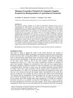
displayed the typical XRD pattern of HKUST-1 (Fig. 1a), and significant
N2 adsorption with a calculated ABET of 1295 m2g-1 (Fig. 1b). Analysis by
SEM of the recovered monoliths showed micrometric HKUST-1 poly
hedral particles placed on the aerogel macropores and partially wrapped
with small pieces of GO flakes (likely, coming from the breaking of the
large GO sheets due to ultrasonication during processing) (Fig. 2a and
b). From the position of the GO flakes, perpendicular to the MOF surface,
it can be inferred that the interaction between both phases preferentially
occurs through the edges of the high aspect ratio sheets of GO, region
where the carboxylic acid functionalities are located. A similar study
was then carried out by using HKUST-1 of nanometric size (nHKUST-1,
30–50 nm, ABET = 1790 m2g-1). In this case, and following a similar
synthetic protocol than for μHKUST-1@GO, the bluish color was now
uniform thorough out the whole monolith, since stable dispersions of GO
and nHKUST-1 in EtOH could be easily prepared when using MOF NPs.
The ex situ nHKUST-1@GO composite (70 wt% for HKUST-1 determined
by ICP-MS) displayed only the XRD signals of HKUST-1 (Fig. 1a), but
with a certain widening of the peaks that reflects the small crystal size of
the NPs. An ABET value of 1125 m2g-1 was calculated from the N2
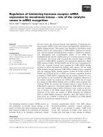
adsorption data (Fig. 1b). SEM micrographs indicated that the NPs were
deposited decorating the flakes surface in a mostly disaggregated mode
(Fig. 2c and d).
Contrary to the above methodology, the in situ method involves the
growth of HKUST-1 NPs from a system containing dissolved MOF re
agents (Cu(NO3)2⋅3H2O and BTC) in EtOH, sodium acetate and
dispersed GO. After supercritical treatment, the percentage of HKUST-1
in the aerogel was of 68 wt%, as determined by ICP-MS, slightly lower
than the target amount of 75 wt%, but in the range of the value
measured for the ex situ sample. The XRD pattern of the obtained in situ
nHKUST-1@GO composite also showed peaks widening, indicating
small crystal size for the in situ synthetized NPs. (Fig. 1a). Actually, SEM
images showed that tiny HKUST-1 NPs of 25–30 nm with a narrow
particle size distribution were grown on the surface of the GO flakes
(Fig. 2e and f). However, a worse distribution of the NPs and higher
degree of aggregation was observed for the in situ sample (Fig. 2e and f)
The percentage of MOF in the prepared composites was determined
from the metal atomic ratio, which was measured by inductively
coupled plasma mass spectrometry (ICP-MS, Agilent 7700x) after solids
digestion in hydrochloric and nitric acids. The structure of the com
posites was characterized by routine powder X-ray diffraction (XRD) in a
Siemens D-5000 diffractometer. The morphological features were
examined by scanning electron microscopy (SEM) in a Quanta FEI 200
equipment. Moreover, High Resolution SEM and Scanning Transmission
Electron Microscopy (STEM) images were collected on a FEI Magellan
400L XHR Field Emission Scanning Electron (FE-SEM) microscope also
used to observe the atomic distribution of metals by energy dispersive
spectroscopy (EDS). The textural properties were determined by N2
adsorption/desorption at − 196 ◦ C using an ASAP 2020 Micromeritics
Inc. apparatus. Previous to measurement, samples were outgassed under
reduced pressure at 80 ◦ C during 20 h. The apparent specific surface area
was calculated by applying the BET (Brunauer, Emmet, Teller) equation
(ABET).
3. Results and discussion
To standardize the scCO2 method for MOF@GO composite aerogels
preparation, three different MOFs were chosen for study: hydrophilic
HKUST-1 and UiO-66 and hydrophobic ZIF-8, all of them synthetized as
NPs. These three MOFs were incorporated into a GO aerogel matrix
described and fully characterized as a singular entity in a previous work
[7]. The overall scCO2 ex situ and in situ synthetic routes are described
below.
3.1. HKUST-1@GO
HKUST-1 is a hydrophilic MOF, with formulae Cu3(BTC)2, involving
a binuclear paddle-wheel copper complex linked by BTC molecules
forming a cubic network [31]. This framework contains a bimodal pore
size distribution, characterized by square channels of 0.9 nm diameter
and small pores with 0.35 nm size. The calculated specific surface area
for the defect-free structure is given as 2153 m2g-1 [32]. Composites
combining HKUST-1, which has potential open metal sites, and gra
phene have been exploited to engineer beneficial pore structures tar
geted to the adsorption and separation of small gas molecules, such as
CO2, methane (CH4) and hydrogen (H2) [33]. Synergistic effects
improving gas adsorption have already been reported for GO or
rGO/HKUST-1 composites [26,34]. HKUST-1, an easily synthetized
product under soft chemical conditions [35], was here chosen as a clear
example of a MOF that can be used for building aerogel composites with
Fig. 1. Characterization of HKUST-1 derived composites: (a) XRD patterns, including the simulated profile of HKUST-1 powder obtained from single-crystal data, and
(b) N2 adsorption/desorption isotherms.
3
A. Borr´
as et al.
Microporous and Mesoporous Materials 335 (2022) 111825
Fig. 2. SEM micrographs at two different magnifications of the cross-section of: (a,b) ex situ μHKUST-1@GO, (c,d) ex situ nHKUST-1@GO, and (e,f) in situ nHKUST1@GO composite aerogels. Insets in (a), (c) and (e) are optical pictures of the monoliths recovered from the synthesis.
with respect to the ex situ counterpart (Fig. 2c and d), which also results
in a slightly lower N2 adsorption (Fig. 1b) and ABET value of 949 m2g-1.
The preferential covering with NPs of the flake edges can be observed in
the high magnification micrographs of the in situ nHKUST-1@GO com
posite (Fig. 2f).
product cannot be obtained by the in situ method due to the solvents
involved in the synthesis of UiO-66. On one hand, this MOF is typically
synthetized through solvothermal methods involving DMF, a solvent
with notable basicity that acts as a deprotonating agent for the BDC
linker. When a strong deprotonating agent is not used, UiO-66 is
precipitated with a large amount of intrinsic defects, which greatly
affect the adsorption properties. On the other hand, the use of DMF is not
recommended in scCO2 processing due to the low solubility of this highboiling point solvent in scCO2 [39]. On the contrary, the UiO-66@GO
aerogel was easily obtained by the ex situ method by adding UiO-66
pre-synthetized NPs (10–20 nm, ABET = 1120 m2g-1) to a GO suspen
sion in EtOH. The recovered UiO-66@GO composite has a UiO-66 pro
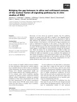
portion of 67 wt% determined by ICP-MS. XRD analysis of the
cylindrical grey monoliths recovered from the reactor confirmed that
the crystal structure of UiO-66 was unaltered in the composite (Fig. 3a).
The estimated ABET value from the N2 adsorption isotherm was 854
m2g-1 (Fig. 3b). SEM images showed a GO network decorated with
constituent UiO-66 NPs (Fig. 4a), in which the MOF NPs have the ability
of aggregating during processing to form a secondary open network
deposited on the surface of the GO flakes (Fig. 4b). This secondary
3.2. UiO-66@GO
UiO-66 is a hydrophilic MOF made of secondary building units
composed of a ZrO complex bridged by BDC ligands. It contains two
separate cages of 0.75 and 1.2 nm diameters, the later with a pore
aperture of 0.6 nm [36]. The theoretical surface area obtained from
geometric modeling of the ideal crystal has been reported as 1550 m2g-1
[37]. Recently, UiO-66, and other isoreticular MOFs of the Zr-family,
have received considerable attention for being used for water purifica
tion purposes, mainly due to the unique Zr(IV)− O bond water stability
across a broad pH range [38].
Following the previous study of HKUST-1, the preparation of GO
aerogels involving UiO-66 NPs was initially attempted by both the ex situ
and in situ methods. However, it was shortly noticed that a proper
4
A. Borr´
as et al.
Microporous and Mesoporous Materials 335 (2022) 111825
Fig. 3. Characterization of UiO-66 derived composites: (a) XRD patterns before and after water immersion, including the simulated profile of UiO-66 from singlecrystal data, and (b) N2 adsorption/desorption isotherms.
Fig. 4. SEM micrographs at two magnifications (a,b) of the cross-section of the ex situ UiO-66@GO prepared monoliths. The inset in (a) is an optical picture of the
recovered monoliths.
system would contribute to the total mesoporosity, which is reflected in
the extraordinary N2 adsorption values observed at high relative pres
sures (Fig. 3b).
known to degrade to a complex carbonated phase in the presence of
humid CO2 [44]. This phase is represented in the XRD pattern by an
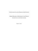
intense peak at 2θ ca. 11◦ (Fig. 5a), and it was recurrently emerging, in
more or less extension, in all the experiments performed in ethanol with
ZIF-8. Low N2 adsorption at low relative pressures and ABET value, in the
order of 500 m2g-1, were determined for the ex situ ZIF-8/carbonated
phase@GO composite due to the lack of porosity of this carbonated
phase (Fig. 5b). Opportunely, ZIF-8 is prone to be synthesized under soft
chemical conditions without the need of strong basic solvents. Hence,
the supercritical experiments for the preparation of ZIF-8@GO aerogels
could be easily performed by using the in situ method, taking into ac
count that the use of ethanol must be avoided as a dispersing solvent in
order to minimize the presence of carbonated phases. Instead, ethyl
acetate, a solvent miscible with compressed CO2, was used to perform
the ZIF-8 experiments. Contrary to EtOH, ethyl acetate is not miscible
with water and water traces can be easily removed. This polar aprotic
solvent could also be used to prepare stable dispersions of GO. For that,
the EtOH in the GO dispersion was exchanged by EA in a step-wise
process. The in situ aerogel preparation process continued by adding
to the EA suspension the corresponding amounts of Zn(acac)2 and
Hmim. EA was then extracted following the scCO2 described protocol for
aerogel formation to get the monoliths. The in situ ZIF-8@GO recovered
aerogel has a composition of 65 wt% for the MOF determined by
ICP-MS. In this case, the powder XRD pattern of the dry aerogel shows
the reflections of ZIF-8, stressing the absence of the carbonate peak at 2θ
ca. 11◦ (Fig. 5a). The calculated ABET value from the N2 adsorption data
was 1308 m2g-1 (Fig. 5b). SEM images of this composite aerogel revealed
GO nanosheets coated with fine ZIF-8 NPs of ca. 50 nm. Aggregates of
NPs were not observed, but the covering of the flakes was not totally
3.3. ZIF-8@GO
ZIF-8, with formula [Zn(2-methylimidazole)2]n, has a hydrophobic
zeolitic framework with sodalite topology. The structure contains one
central nanopore per unit cell, with a diameter of 1.16 nm, that is
interconnected by narrow windows of 0.34 nm. Under particular con
ditions, this compound shows structural flexibility, which can increase
the window opening up to ca. 0.6 nm [40,41]. The crystallographic
apparent surface area for an infinite crystal has been calculated as 1947
m2g-1 [42]. With extremely high thermal, chemical and mechanical
stability, ZIF-8 has provided the MOFs scientific community with an
enormous number of potential uses, including gas separation, catalysis,
electrode for batteries and so on [43].
The synthesis of ZIF-8@GO composites was here attempted by the ex
situ and in situ supercritical methods. Contrarily to UiO-66@GO aerogel,
the composite based on ZIF-8 could only be constructed by using the in
situ method. In this particular case, the use of the ex situ route led to the
collapse of the GO suspension when adding pre-synthetized ZIF-8 NPs.
The suspension involving both nanomaterials was totally unstable and,
as a consequence, the scCO2 treatment could not form the expected low
density aerogel. This behavior was rationalized on the basis of the dis
similar hydrophobic (ZIF-8) and hydrophilic (GO) character of both
components. A second observed drawback in the supercritical method
was related to the low stability of ZIF-8 in a medium involving ethanol,
with some inevitably dissolved water, and concentrate CO2. This MOF is
5
A. Borr´
as et al.
Microporous and Mesoporous Materials 335 (2022) 111825
Fig. 5. Characterization of ZIF-8 derived composites: (a) XRD patterns, including the simulated profile of ZIF-8 from single-crystal data, and the carbonated phase
obtained by treating ZIF-8 in EtOH under scCO2 conditions for a long period of time, and (b) N2 adsorption/desorption isotherms.
homogeneous, since few of them has a low amount of deposited ZIF-8,
while other were totally coated (Fig. 6).
high degree of dryness is necessary to avoid secondary processes, such as
metal carbonation occurring for ZIF-8.
By analyzing the behavior of different MOFs, it was stablished that
the interactions between MOF and GO were notably determined by the
wetting nature of the NPs and the matrix flakes. Actually, the hydro
phobic or hydrophilic nature of the MOF is identified in this work as one
of the most important parameters defining the choice of either the ex situ
or in situ scCO2 synthetic protocol that is based on the use of hydrophilic
GO dispersions (Fig. 7). Ex situ synthesis approaches consist in inte
grating pre-synthetized NPs and GO during scCO2 drying (Fig. 7a). Since
GO and MOF surfaces have different charges, the electrostatic in
teractions between the two materials lead to self-assembly of both
dispersed solids. The in situ route consists of mixing MOF precursors and
GO, followed by scCO2 drying (Fig. 7b). In this case, the oxygenated
functionalities in GO serve as nucleation points for the MOF. For the
particular systems studied in this work, it was stablished that for some
MOFs, like HKUST-1, composite aerogels can be built using both the ex
situ and in situ methods, and with micro and nanoparticles. However,
this was not always possible for all the MOFs. Hence, UiO-66@GO is an
example of an aerogel that could only be constructed by the ex situ route,
while, contrarily, ZIF-8@GO typifies an aerogel only obtained by the in
situ method.
During gel dryness using scCO2, a high degree of the exfoliation
attained for GO flakes by sonication in the dispersing liquid was main
tained. This was demonstrated through the structural characterization
performed by XRD that did not show for any of the synthetized com
posites the broad signal characteristic of GO at ca. 11◦ (Figs. 1a, 3a and
5a) [45]. The lack of this signal was ascribed, on one side, to the low
contribution of GO to the total weight of the samples, determined by
3.4. Method overview screen
The main purpose behind using the scCO2 processing method for the
preparation of these composites was to obtain highly mesoporous (nonreduced) GO aerogels instead of the typically synthetized (reduced) rGO.
As mentioned, this is feasible thanks to the low critical temperature of
CO2 that allows materials processing under soft thermal conditions. It
has been shown that the used GO starts to undergo reduction when the
synthesis temperature reaches near 100 ◦ C, so this temperature was
never exceeded in this work neither during the drying or the posterior
activation step [7]. The quality of the liquid replacement by CO2 is
crucial for attaining proper monolithic aerogel samples. Free solvent
located outside the gel is rapidly dragged by CO2, while solvent within
the gel is difficult to remove, needing a long period of time for extrac
tion. However, this is important to prepare structurally stable aerogels of
GO, since during the slow extraction process the gel is also aging, which
is needed for the strengthening of the gel network. The particularities of
scCO2 must be also considered in regard of its capacity for eliminating
the solvent from the gel precursor, the formation of which is unavoid
able to obtain a proper aerogel. Hence, the solvent to dry must be
significantly soluble in scCO2, which is essentially limited to organic
liquids with low molecular weight and relatively low vapor pressure. In
the proposed scCO2 generic method for MOF@GO composites prepara
tion, EtOH is used as the first option, since this alcohol has been
demonstrated to form stable and highly oxygenated net GO aerogels.
This work shows that ethyl acetate is also an adequate solvent when a
Fig. 6. SEM micrographs at two magnifications (a,b) of the cross-section of the in situ ZIF-8@GO prepared monoliths. The inset in (a) is an optical picture of the
recovered monoliths.
6
A. Borr´
as et al.
Microporous and Mesoporous Materials 335 (2022) 111825
Fig. 7. Schematic representation of the scCO2 protocols used for MOF@GO aerogel preparation: (a) ex situ, and (b) in situ.
ICP-MS to be in the range of 30–35 wt% (slightly higher than the target
initial value of 25 wt%); and, on the other side, to the amorphization of
solid GO caused by a decrease in the staking of the flakes due to MOF
NPs deposition between layers. The recorded N2 adsorption/desorption
isotherms for the different composites indicated a hierarchical micro/
meso pore size distribution for all of them (Figs. 1b, 3b and 5b), denoted
by substantial adsorption at very low pressures (microporosity given by
the MOF) and, also, significant adsorption at high relative pressures
including hysteresis (mesoporosity given mainly by the aerogel and only
partially by NPs aggregation).
SEM micrographs of aerogel cross-section of the synthetized
MOF@GO composites revealed a sponge-like skeleton built by GO
flakes, which is structured in a 3D continuous network, and a discon
tinuous phase of MOF NPs decorating GO surface in a relatively welldistributed mode (Fig. 2c,e, 4a,b and 6a,b). For the ex situ protocol,
the size of the deposited NPs can be easily determined, since they are
pre-synthetized, and varied between the micro and nanometric range.
Contrarily, the interactions of GO with the metal center strongly impact
the size of the in situ synthetized MOF NPs within the composite, likely
by favoring nucleation vs. crystal growth, and leading to very small
particles decorating GO surface. A somehow worst distribution and
higher degree of aggregation was observed for the in situ samples in
comparison to the ex situ counterparts. This effect was attributed to the
binding competition stablished in the first reaction steps during the in
situ process between the GO oxygenated groups and the reactive atoms
of the MOF linker for the metal cation reactive sites, which disturbed the
thermodynamic equilibrium of the MOF reaction. For instance, smaller
particle size and higher degree of aggregation was observed in the SEM
images of HKUST-1 NPs deposited on GO flakes for aerogels obtained
following the in situ protocol (Fig. 2e and f) in comparison to those of the
ex situ route (Fig. 2c and d). In the same line, an inhomogeneous
covering of the GO surface was observed for the in situ formed ZIF-8@GO
aerogels, with some GO flakes perfectly covered by NPs and some of
them only decorated with few aggregated spots (Fig. 6). For the ZIF8@GO system, this drawback was solved by adding adjuvant PVP, in a
concentration of 5 wt%, to the GO EA dispersion. In this way, GO was
conjugated with PVP previous to ZIF-8 reagents addition. This polymer
was chosen because it has a high affinity for ZIF-8 and its adsorption to
this MOF is restricted to the surface [46]. For the recovered
ZIF-8@GO/PVP composite aerogel, XRD showed that ZIF-8 was the only
crystalline phase (Fig. 5a). The calculated ABET value was 1002 m2g-1
(Fig. 5b), slightly lower than that of ZIF-8@GO aerogel, but in the same
magnitude. The minor decrease in the apparent specific surface area
mainly arises from the presence of a nonporous phase (PVP) in the
composite, which contributes to the weight but not to the porosity.
Interestingly, for the ZIF-8@GO/PVP aerogel, the small ZIF-8 NPs were
homogeneously distributed on the GO flakes (Fig. 8a). STEM images
showed that the NPs suffer a kind of lateral aggregation, nearly fully
covering the GO surface. The presence of PVP offered extra nucleation
points during the formation of ZIF-8, thus improving the coating of GO
flakes. Moreover, the experiments performed in this work demonstrate
that the supercritical in situ approach can be used to prepare aerogels not
only with high-density of microporous NPs, but also neatly distributed
on both sides of the 2D GO nanosheets (Fig. 8b). These characteristics
made these composites potential candidates in advanced membrane
technology for the fabrication of ultrathin molecular sieves for liquid
and gases, also thanks to the synergetic hydrophobic and oleophobic
nature of ZIF-8 and GO [47]. GO, by itself, has been shown to be highly
impermeable due to the closely packed arrangement of carbon atoms in
the lattice [48]. ZIF-8 NPs decorating GO surface acted as a spacer and
protective layer to prevent severe aggregation and destruction of the
mesoporosity [49].
Composites prepared through the scCO2 route were always recov
ered with the shape of the used round bottom vials (insets of optical
pictures in Figs. 2, 4 and 6), since the aerogel mimics the shape of the
recipient in which it is contained. This is because it is formed through a
gel phase. This is considered one important advantage, since the scCO2
method would enable the fabrication of MOF@GO aerogels with
different and complex shapes just by using different molds, as it is
exemplified for the HKUST-1@GO aerogel in Fig. 9. This fact could have
multiple applications, from the design of scaffolds in biomedicine with
intricate geometries (Fig. 9a) [50] to the growth of adsorbents inside
fixed-bed columns for gas separation processes (Fig. 9b) [26].
Even though the ex situ method cannot be used in all the cases, as
demonstrated for the ZIF-8@GO composite, it has some advantages vs.
the in situ route. Those are essentially related to the lack of binding
competence for the metal reactive sites and enhanced NPs dispersion.
One extra particularity of the ex situ method is that it can be used to
easily prepare systems with two (or more) kind of NPs. This potentiality
of the scCO2 ex situ route was demonstrated in this work by constructing
in EtOH a ternary composite involving GO, UiO-66 and super
paramagnetic magnetite (Fe3O4) NPs of ca. 10 nm diameter [51], in a
ratio UiO-66:Fe3O4:GO 2:1:2 wt. In the XRD pattern of the resulting
UiO-66/Fe3O4@GO composite only the peaks of UiO-66 were observed.
The lines of Fe3O4 were not displayed due to low loading of this
component and small particle size (Fig. 3a). N2 adsorption isotherms
indicated that the micro/meso porous structure was preserved in the
ternary composite, although the adsorption at very low pressures,
indicating microporosity, slightly diminished due to the lower per
centage of the microporous component UiO-66 in the UiO-66/
Fe3O4@GO aerogel with respect to UiO-66@GO (Fig. 3b). Thus, the
calculated ABET was of only 470 m2g-1, reflecting the presence of the
7
A. Borr´
as et al.
Microporous and Mesoporous Materials 335 (2022) 111825
Fig. 8. Images taken by: (a) STEM, and (b) SEM of ZIF-8@GO/PVP aerogel.
Fig. 9. Optical pictures of nHKUST-1@GO aerogel blocks obtained in scCO2 by the in situ route: (a) two different shapes, e.g., a flower and a pyramid, together with
their respective molds, and (b) gas separation column with the aerogel grown inside and extracted monolith.
non-porous Fe3O4 phase (Fig. 3b). In the SEM images of the UiO-66/
Fe3O4@GO sample, UiO-66 and Fe3O4 NPs could not be distinguished. In
spite of this, the presence of magnetite in the composite was proved by
EDS analysis, in which both Zr and Fe atoms were clearly visible
distributed through the aerogel (Fig. 10a). Fe3O4 NPs were relatively
well distributed in the sample, only showing some spots of aggregates.
The final product was a magnetic aerogel (Fig. 10b), considered a pro
totype material to be used in water purification processes. In fact,
UiO-66/Fe3O4 composites have already demonstrated to be efficient
adsorbents for heavy metal ions and cationic/anionic organic dyes
removal from aqueous solution [52,53]. It is worth mentioning that, for
this application, the aerogel UiO-66/Fe3O4@GO must be made first
Fig. 10. UiO-66/Fe3O4@GO: (a) characterized by SEM with the derived EDS mappings of Zr (pink) and Fe (blue), and (b) reduction to UiO-66/Fe3O4@rGO showing
the magnetic character and water stability. (For interpretation of the references to color in this figure legend, the reader is referred to the Web version of this article.)
8
A. Borr´
as et al.
Microporous and Mesoporous Materials 335 (2022) 111825
stable in water, which is accomplished by prompting the reduction of
the hydrophilic GO network to hydrophobic rGO. This can be easily
achieved by slowly heating the composite at 190–200 ◦ C under a N2
flow. The resulting product, UiO-66/Fe3O4@rGO, is stable in water,
displaying after water treatment and drying a similar XRD profile than
the original composite (Fig. 3a) and still magnetic (Fig. 10b). As a final
advantageous point, the use of magnetic additives, providing magnetic
susceptibility in front of an external field, would facilitate the separation
of the monolith from the purified solution for reuse [54].
Using the described ex situ route, ternary composites were straight
forwardly prepared in a one-pot route. Moreover, the amount of each
component could be easily adjusted by just weighing the desired amount
of each component. As demonstrated, this process works properly for the
system UiO-66/Fe3O4@GO. However, some drawbacks are foreseen for
the formation of ternary composites using the in situ route, mainly
related to the different reaction rates of the components and challenges
in finding a single solvent adequate for products reaction and aerogel
formation. For highly hydrophobic compounds that flocculate the aer
ogel when added as NPs, as ZIF-8, the formation of the ternary com
posite ZIF-8/Fe3O4@rGO could be operated in a two-steps process, in
which first Fe3O4 is deposited on GO following the ex situ methodology
and, then, ZIF-8 is in situ synthetized on the Fe3O4@GO surface during
aerogel formation in scCO2.
Acknowledgements
This work was supported by the Spanish Ministry of Science and
Innovation MICINN through the Severo Ochoa Program for Centers of
Excellence (SEV-2015-0496 and CEX2019-000917-S) and the Spanish
National Plan of Research with projects CTQ2017-83632, PID2020115631GB-I00. This work has been done in the framework of the
`noma de Barce
doctoral program “Chemistry” of the Universitat Auto
lona by A.B., A.R. and J.F.; A.B. and A.R. acknowledge FPI grants.
References
[1] A.C. Pierre, G.M. Pajonk, Chemistry of aerogels and their applications, Chem. Rev.
102 (2002) 4243–4266, />[2] J.L. Gurav, I.-K. Jung, H.-H. Park, E.S. Kang, D.Y. Nadargi, Silica aerogel: synthesis
and applications, J. Nanomater (2010), 409310, />409310.
[3] F. Akhter, S.A. Soomro, V.J. Inglezakis, Silica aerogels; a review of synthesis,
applications and fabrication of hybrid composites, J. Porous Mater. 28 (2021)
1387–1400, />[4] G. Nassar, E. Daou, R. Najjar, M. Bassil, R. Habchi, A review on the current research
on graphene-based aerogels and their applications, Carbon Trends 4 (2021),
100065, />[5] M. Kotal, J. Kim, J. Oh, I.-K. Oh, Recent progress in multifunctional graphene
aerogels, Front. Mater. 3 (2016) 29, />[6] G. Maskim Vladimirovich, V. Pavlovich Melnikov, Graphene oxide/reduced
graphene oxide aerogels, Graphene Oxide Appl. Oppor. (2018) 39–55, https://doi.
org/10.5772/intechopen.78987.
[7] A. Borr
as, G. Gonỗalves, G. Marb
an, S. Sandoval, S. Pinto, P.A.A.P. Marques,
J. Fraile, G. Tobias, A.M. L´
opez-Periago, C. Domingo, Preparation and
characterization of graphene oxide aerogels: exploring the limits of supercritical
CO2 fabrication methods, Chem. Eur J. 24 (2018) 15903–15911, />10.1002/chem.201803368.
[8] Z. Sun, Q. Fan, M. Zhang, S. Liu, H. Tao, J. Texter, Supercritical fluid-facilitated
exfoliation and processing of 2D materials, Adv. Sci. 6 (2019), 1901084, https://
doi.org/10.1002/advs.201901084.
[9] S. Stankovich, D.A. Dikin, G.H.B. Dommett, K.M. Kohlhaas, E.J. Zimney, E.
A. Stach, R.D. Piner, S.T. Nguyen, R.S. Ruoff, Graphene-based composite materials,
Nature 442 (2006) 282–286, />[10] V.B. Mohana, K.-T. Laub, D. Huic, D. Bhattacharyyaa, Graphene-based materials
and their composites: a review on production, applications and product limitations,
Composites B 142 (2018) 200–220, />compositesb.2018.01.013.
[11] A. Borr´
as, J. Fraile, A. Rosado, G. Marb´
an, G. Tobias, A.M. L´
opez-Periago,
C. Domingo, Green and solvent-free supercritical CO2-assisted production of
superparamagnetic graphene oxide aerogels: application as a superior contrast
agent in MRI, ACS Sustain. Chem. Eng. 8 (2020) 4877–4888, />10.1021/acssuschemeng.0c00149.
[12] A.U. Czaja, N. Trukhan, U. Müller, Industrial applications of metal–organic
frameworks, Chem. Soc. Rev. 38 (2009) 1284–1293, />B804680H.
[13] H.-C. Zhou, J.R. Long, O.M. Yaghi, Introduction to metal–organic frameworks,
Chem. Rev. 112 (2012) 673–674, />[14] Q. Wang, D. Astruc, State of the art and prospects in metal–organic framework
(MOF)-Based and MOF-derived nanocatalysis, Chem. Rev. 120 (2020) 1438–1511,
/>[15] D.W. Kim, K. Eum, H. Kim, D. Kim, M.D. de Mello, K. Park, M. Tsapatsis,
Continuous ZIF-8/reduced graphene oxide nanocoating for ultrafast oil/water
separation, Chem. Eng. Sci. 372 (2019) 509–515, />cej.2019.04.179.
[16] Y. Zheng, S. Zheng, H. Xue, H. Pang, Metal-organic frameworks/graphene-based
materials: preparations and applications, Adv. Funct. Mater. 28 (2018) 1–28,
/>[17] X.-W. Liu, T.-J. Sun, J.-L. Hu, S.-D. Wang, Composites of metal–organic frameworks
and carbon-based materials: preparations, functionalities and applications,
J. Mater. Chem. 4 (2016) 3584–3616, />[18] M. Muschi, C. Serre, Progress and challenges of graphene oxide/metal-organic
composites, Coord. Chem. Rev. 387 (2019) 262–272, />ccr.2019.02.017.
[19] S. Korkmaz, A. Kariper, Graphene and graphene oxide based aerogels: synthesis,
characteristics and supercapacitor applications, J. Energy Storage 27 (2020),
1010382, />[20] X. Xu, W. Shi, P. Li, S. Ye, C. Ye, H. Ye, T. Lu, A. Zheng, J. Zhu, L. Xu, M. Zhong,
X. Cao, Facile fabrication of three-dimensional graphene and metal–organic
framework composites and their derivatives for flexible all-solid-state
supercapacitors, Chem. Mater. 29 (2017) 6058–6065, />acs.chemmater.7b01947.
[21] X. Zheng, Y. Cao, D. Liu, M. Cai, J. Ding, X. Liu, J. Wang, W. Hu, C. Zhong,
Bimetallic metal–organic-framework/reduced graphene oxide composites as
bifunctional electrocatalysts for rechargeable Zn–Air batteries, ACS Appl. Mater.
Interfaces 11 (2019) 15662–15669, />
4. Conclusions
Nanohybrid composites based on MOFs and GO enable the integra
tion of the unique properties of these two fascinating materials. This
study demonstrates that it is feasible to apply the scCO2 drying tech
nology to build up monoliths of these composites following either the ex
situ (direct mixing during) or in situ (MOF growth) protocol. The scCO2
strategy performs as a synthetic platform, including assisted gelation,
gel aging and drying, and fabrication of GO aerogels decorated with
MOF particles. The ex situ route is a very general method that can be
applied to a large number of MOFs, rather with a hydrophilic nature.
Moreover, it can be easily extended to prepare ternary composites, for
instance involving magnetic NPs. The in situ method is a one-pot pro
cedure that can be used to save time and resources and can be also
applied to hydrophobic MOFs. GO is in this route envisaged as a
structure-directing agent for the growth and/or stabilization of MOF
particles, with or without the addition of adjuvant polymers, where
coordination modulation occurs through the different functional groups
on the surface. Using the scCO2 green technology, it is possible to
structure these composites with hierarchical porosity (micro, meso and
macro). GO composites are considered a more versatile material than
rGO composites, since the former can be easily (thermal or chemically)
reduced to rGO on demand. Envisaged applications for these materials
are related to adsorption, outstanding those of gas separation, water
purification and molecular sieving membranes.
CRediT authorship contribution statement
´s: Methodology, Investigation, Data curation,
Alejandro Borra
Conceptualization. Albert Rosado: Methodology, Investigation. Julio
´ pez-Periago: Writing – review & editing,
Fraile: Validation. Ana M. Lo
´ Giner Planas: Writing – review & editing,
Funding acquisition. Jose
´n
Methodology. Amirali Yazdi: Methodology, Investigation. Concepcio
Domingo: Writing – review & editing, Writing – original draft, Super
vision,
Methodology,
Funding
acquisition,
Data
curation,
Conceptualization.
Declaration of competing interest
The authors declare that they have no known competing financial
interests or personal relationships that could have appeared to influence
the work reported in this paper.
9
A. Borr´
as et al.
Microporous and Mesoporous Materials 335 (2022) 111825
[22] X. Zhang, Q. Liang, Q. Han, W. Wan, M. Ding, Metal–organic frameworks@
graphene hybrid aerogels for solid-phase extraction of non-steroidal antiinflammatory drugs and selective enrichment of proteins, Analyst 141 (2016)
4219–4226, />[23] J. Mao, M. Ge, J. Huang, Y. Lai, C. Lin, K. Zhang, K. Meng, Y. Tang, Constructing
multifunctional MOF@rGO hydro-/aerogels by the self-assembly process for
customized water remediation, J. Mater. Chem. 5 (2017) 11873–11881, https://
doi.org/10.1039/C7TA01343D.
[24] W. Xia, C. Qu, Z. Liang, B. Zhao, S. Dai, B. Qiu, Y. Jiao, Q. Zhang, X. Huang,
W. Guo, D. Dang, R. Zou, D. Xia, Q. Xu, M. Liu, High-performance energy storage
and conversion materials derived from a single metal–organic framework/
graphene aerogel composite, Nano Lett. 17 (2017) 2788–2795, />10.1021/acs.nanolett.6b05004.
[25] X. Qiu, X. Wang, Y. Li, Controlled growth of dense and ordered metal–organic
framework nanoparticles on graphene oxide, Chem. Commun. 51 (2015)
3874–3877, />[26] A. Rosado, A. Borr´
as, J. Fraile, J.A.R. Navarro, F. Su´
arez-García, K.C. Stylianou, A.
M. L´
opez-Periago, J. Giner Planas, C. Domingo, A. Yazdi, HKUST-1 metal–organic
framework nanoparticle/graphene oxide nanocomposite aerogels for CO2 and CH4
adsorption and separation, ACS Appl. Nano Mater. 4 (2021) 12712–12725, https://
doi.org/10.1021/acsanm.1c03301.
[27] L. Chen, X. Zhang, X. Cheng, Z. Xie, Q. Kuang, L. Zheng, The function of
metal–organic frameworks in the application of MOF-based composites, Nanoscale
Adv. 2 (2020) 2628–2647, />[28] N.C. Jeong, B. Samantha, C.Y. Lee, O.K. Farha, J.T. Hupp, Coordination-chemistry
control of proton conductivity in the iconic metal–organic framework material
HKUST-1, J. Am. Chem. Soc. 134 (2012) 51–54, />ja2110152.
[29] C. Xin, H. Zhan, X. Huang, H. Li, N. Zhao, F. Xiao, W. Wei, Y. Sun, Effect of various
alkaline agents on the size and morphology of nano-sized HKUST-1 for CO2
adsorption, RSC Adv. 5 (2015) 27901–27911, />C5RA03986J.
[30] B. Bueken, N. Van Velthoven, T. Willhammar, T. Stassin, I. Stassen, D.A. Keen, G.
V. Baron, J.F.M. Denayer, R. Ameloot, S. Bals, D. De Vos, T.D. Bennett, Gel-based
morphological design of zirconium metal–organic frameworks, Chem. Sci. 8 (2017)
3939–3948, />[31] S.S.-Y. Chui, S.M.-F. Lo, J.P. Charmant, A.G. Orpen, I.D. Williams, A chemically
functionalizable nanoporous material, Science 283 (1999) 1148–1150, https://doi.
org/10.1126/science.283.5405.1148.
[32] T. Düren, F. Millange, G. F´
erey, K.S. Walton, R.Q. Snurr, Calculating geometric
surface areas as a characterization tool for metal - organic frameworks, J. Phys.
Chem. C 111 (2007) 15350–15356, />[33] S. Liu, L. Sun, F. Xu, J. Zhang, C. Jiao, F. Li, Z. Li, S. Wang, Z. Wang, X. Jiang,
H. Zhou, L. Yang, C. Schick, Nanosized Cu-MOFs induced by graphene oxide and
enhanced gas storage capacity, Energy Environ. Sci. 6 (2013) 818–823, https://doi.
org/10.1039/C3EE23421E.
[34] T.J. Bandosz, C. Petit, MOF/Graphite oxide hybrid materials: exploring the new
concept of adsorbents and catalysts, Adsorption 17 (2011) 5–16, />10.1007/s10450-010-9267-5.
[35] X. Mu, Y. Chen, E. Lester, T. Wu, Optimized synthesis of nano-scale high quality
HKUST-1 under mild conditions and its application in CO2 capture, Microporous
Mesoporous Mater. 270 (2018) 249–257250, />micromeso.2018.05.027.
[36] J. Winarta, B. Shan, S.M. Mcintyre, L. Ye, C. Wang, J. Liu, B. Mu, A decade of UiO66 research: a historic review of dynamic structure, synthesis mechanisms, and
characterization techniques of an archetypal Metal− Organic framework, Cryst.
Growth Des. 20 (2020) 1347–1362, />[37] M.J. Katz, Z.J. Brown, Y.J. Col´
on, P.W. Siu, K.A. Scheidt, R.Q. Snurr, J.T. Hupp, O.
K. Farha, A facile synthesis of UiO-66, UiO-67 and their derivatives, Chem.
Commun. 49 (2013) 9449–9451, />
[38] Z. Hu, D. Zhao, De facto methodologies toward the synthesis and scale-up
production of UiO-66-type metal-organic frameworks and membrane materials,
Dalton Trans. 44 (2015) 1901819040, />[39] M. Jă
odecke, A. P
erez-Salado Kamps, G. Maurer, An experimental investigation of
the solubility of CO2 in (Acetone + water), J. Chem. Eng. Data 57 (2012)
1249–1266, />[40] D. Fairen-Jimenez, S.A. Moggach, M.T. Wharmby, P.A. Wright, S. Parsons,
T. Düren, Opening the gate: framework flexibility in ZIF-8 explored by experiments
and simulations, J. Am. Chem. Soc. 133 (2011) 8900–8902, />10.1021/ja202154j.
[41] K. Zhang, R.P. Lively, C. Zhang, R.R. Chance, W.J. Koros, D.S. Sholl, S. Nair,
Exploring the framework hydrophobicity and flexibility of ZIF-8: from biofuel
recovery to hydrocarbon separations, J. Phys. Chem. Lett. 4 (2013) 3618–3622,
/>[42] K.S. Park, Z. Ni, A.P. Cote, J.Y. Choi, R. Huang, F.J. Uribe-Romo, H.K. Chae,
M. O’Keeffe, O.M. Yaghi, Exceptional chemical and thermal stability of zeolitic
imidazolate frameworks, Proc. Natl. Acad. Sci. Unit. States Am. 103 (2006)
10186–10191, />[43] D. Zou, D. Liu, J. Zhang, From zeolitic imidazolate framework-8 to metal-organic
frameworks (MOFs): representative substance for the general study of pioneering
MOF applications, Energy Environ. Mater. 1 (2018) 209–220, />10.1002/eem2.12018.
[44] C. Mottillo, T. Friscic, Carbon dioxide sensitivity of zeolitic imidazolate
frameworks, Angew. Chem. Int. Ed. 53 (2014) 7471–7474, />10.1002/anie.201402082.
[45] D.C. Marcano, D.V. Kosynkin, J.M. Berlin, A. Sinitskii, Z. Sun, A. Slesarev, L.
B. Alemany, W. Lu, J.M. Tour, Improved synthesis of graphene oxide, ACS Nano 4
(2010) 4806–4814, />[46] G. Lu, S. Li, Z. Guo, O.K. Farha, B.G. Hauser, X. Qi, Y. Wang, X. Wang, S. Han,
X. Liu, Imparting functionality to a metal-organic framework material by
controlled nanoparticle encapsulation, Nat. Chem. 4 (2012) 310–316, https://doi.
org/10.1038/nchem.1272.
[47] D.W. Kim, K. Eum, H. Kim, D. Kim, M.D. de Mello, K. Park, M. Tsapatsis,
Continuous ZIF-8/reduced graphene oxide nanocoating for ultrafast oil/water
separation, Chem. Eng. J. 372 (2019) 509–515, />cej.2019.04.179.
[48] H. Li, Z. Song, X. Zhang, Y. Huang, S. Li, Y. Mao, H.J. Ploehn, Y. Bao, M. Yu,
Ultrathin, molecular-sieving graphene oxide membranes for selective hydrogen
separation, Science 342 (2013) 95–98, />[49] Y. Hu, J. Wei, Y. Liang, H. Zhang, X. Zhang, W. Shen, H. Wang, Zeolitic imidazolate
framework/graphene oxide hybrid nanosheets as seeds for the growth of ultrathin
molecular sieving membranes, Angew. Chem. Int. Ed. 55 (2016) 2048–2052,
/>[50] S.R. Shin, Y.-C. Li, H.L. Jang, P. Khoshakhlagh, M. Akbari, A. Nasajpour, Y.
S. Zhang, A. Tamayol, A. Khademhosseini, Graphene-based materials for tissue
engineering, Adv. Drug Deliv. Rev. 105 (2016) 255–274.
[51] Y.S. Kang, S. Risbud, J.F. Rabolt, P. Stroeve, Synthesis and characterization of
nanometer-size Fe3O4 and γ-Fe2O3 particles, Chem. Mater. 8 (1996) 2209–2211,
/>[52] C. Wang, X. Liu, N.K. Demir, J.P. Chenb, K. Li, Applications of water stable
metal–organic frameworks, Chem. Soc. Rev. 45 (2016) 5107–5134, https://doi.
org/10.1039/C6CS00362A.
[53] L. Huang, M. He, B. Chen, B. Hu, Magnetic Zr-MOFs nanocomposites for rapid
removal of heavy metal ions and dyes from water, Chemosphere 199 (2018)
435–444, />[54] R. Kaur, A. Hasan, N. Iqbal, S. Alam, M.K. Saini, S.K. Raza, Synthesis and surface
engineering of magnetic nanoparticles for environmental cleanup and pesticide
residue analysis: a review, J. Separ. Sci. 37 (2014) 1805–1825, />10.1002/jssc.201400256.
10