Mechanical performance of integrally bonded copper coatings for the long term disposal of used nuclear fuel
Bạn đang xem bản rút gọn của tài liệu. Xem và tải ngay bản đầy đủ của tài liệu tại đây (4.36 MB, 10 trang )
Nuclear Engineering and Design 293 (2015) 403–412
Contents lists available at ScienceDirect
Nuclear Engineering and Design
journal homepage: www.elsevier.com/locate/nucengdes
Mechanical performance of integrally bonded copper coatings for the
long term disposal of used nuclear fuel
Christopher H. Boyle a,∗ , Shaker A. Meguid b
a
b
Nuclear Waste Management Organization, 22 St. Clair Ave East, Toronto, Canada
Department of Mechanical and Industrial Engineering, University of Toronto, 5 King’s College Road, Toronto, Canada
h i g h l i g h t s
•
•
•
•
A novel Used Fuel Container with an integrally bonded copper coating is proposed.
Two developed coating processes successfully produced prototype container components.
We created a validated finite element model to predict coating structural performance.
Mechanical testing confirms coating suitably for repository use.
a r t i c l e
i n f o
Article history:
Received 15 April 2015
Received in revised form 29 June 2015
Accepted 4 August 2015
a b s t r a c t
The preferred method for disposal of used nuclear fuel is underground emplacement in a Deep Geological Repository (DGR). Many countries have light water reactor fuels which require large Used Fuel
Container or Canister (UFC) designs weighing up to 25 ton for containment. In contrast, Canada exclusively
uses heavy water reactor fuel, which is substantially smaller. This has led the Nuclear Waste Management Organization (NWMO) to create a novel UFC, which uses standard pressure vessel grade steel for
structural containment and a thick, integrally bonded copper coating applied to the exterior surface for
corrosion protection. Currently, the coating is applied using two different methods: electrodeposition
and gas dynamic cold spray. This novel copper coating needs to be fully validated to ensure adequate
mechanical strength and chemical resistance for use under repository conditions. Detailed mechanical
and corrosion testing programs were undertaken. Mechanical tests indicated that adhesion strengths
exceeded 45 MPa and tensile properties were comparable to wrought copper. A Finite Element Model
(FEM) of the copper–steel composite was created and validated using three point bend tests. This model
accurately predicts the response of the composite, including large deformation and debonding failure
mechanisms. Now validated, this model will be used to assess the performance of the coating on the
full-scale UFC under simulated DGR loading conditions.
© 2015 The Authors. Published by Elsevier B.V. This is an open access article under the CC BY-NC-ND
license ( />
1. Introduction
The internationally preferred method for the long-term disposal
of used nuclear fuel is a Deep Geological Repository (DGR). Many
countries, including Sweden, Switzerland, and Canada, began DGR
research and development as early as the 1970s. Currently, there
are several additional countries pursuing DGRs, including Finland,
Japan, Korea, Belgium, France, and the United Kingdom. The longterm safety of a DGR relies on the use of multiple engineered barrier
systems (EBS), which provide redundant containment, isolation,
∗ Corresponding author. Tel.: +1 6472593736.
E-mail address: (C.H. Boyle).
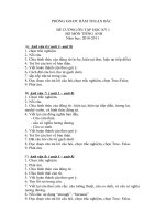
and retardation functions, as shown in Fig. 1. The EBS consists of
used or spent fuel bundles packaged into a long-lived Used Fuel Container or Canister (UFC). The container is surrounded by bentonite
clay, which retards the flow of water and suppresses microbial
growth (Wolfaardt and Korber, 2012; Stroes-Gascoyne et al., 2010).
The DGR is constructed at a depth of over 400 m. The geosphere of
dense rock, which has no free flowing water, limits the movement
of radioactive particles. Natural analogues of DGRs, such as the Cigar
Lake uranium deposit, have effectively isolated high-grade uranium
ore for millions of years (Miller et al., 1994).
Since the beginning of DGR research and development in the
1970s, copper has been a favored material for container corrosion
prevention. Copper was selected due to its thermodynamic stability
from corrosion under DGR conditions and several natural analogues
/>0029-5493/© 2015 The Authors. Published by Elsevier B.V. This is an open access article under the CC BY-NC-ND license ( />0/).
404
C.H. Boyle, S.A. Meguid / Nuclear Engineering and Design 293 (2015) 403–412
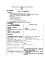
Fig. 2. NWMO’s Mark II Used Fuel Container for CANDU bundles (cut-away shown
for clarity). Approximate dimensions 562 mm (∼22 ) diameter, 2514 mm (∼99 )
length.
Fig. 1. Canada’s Deep Geological Repository (DGR) concept.
proving its performance. These analogues include archaeological artifacts (King, 1995) (i.e. coins, cannons, etc.), which contain
metallic copper, as well as, mineral deposits that contain naturally
occurring metallic copper (Chastain et al., 2011). In addition, corrosion processes that impact the lifespan of copper within a DGR
have been extensively studied for over 30 years by the international
community. Most recent efforts by Canada’s Nuclear Waste Management Organization (NWMO) (Kwong, 2011), as well as independent corrosion experts (Scully and Edwards, 2013) have focused on
developing and reviewing corrosion allowances to account for all
the processes that significantly affect copper materials. From these
reviews, a copper corrosion allowance of less than 1.3 mm has been
deemed appropriate for one million years storage in a Canadian DGR.
This corrosion allowance is very conservative; it is expected that
much less than 1.3 mm of copper will corrode over that time period.
Sweden and Finland have proposed a “dual-vessel” container
design consisting of a large cast-iron inner vessel for structural
strength with a 50 mm thick copper overpack vessel for corrosion protection. This concept is known as the KBS-3 (Svensk
Kärnbränslehantering AB, 2010). NWMO also has a reference dualvessel container design; however, a key design difference is the use
of a hollow inner steel shell for the containment vessel instead of a
honeycomb cast-iron insert. Canada’s heavy water CANDU reactors
use small, natural uranium fuel bundles, which can be packaged as
densely as possible with negligible risk of criticality in water or air.
As a result, a shell design allows more efficient storage of CANDU
bundles by the use of internal baskets. While the dual-vessel design
is technically feasible, there are several potential challenges for
implementation. From a functional perspective, a nominal radial
gap of less than 2 mm between the inner and outer vessel has been
identified as a requirement to limit the creep strain (Raiko et al.,
2010) and prevent rupture from low creep ductility (Petterson,
2012). This requires manufacturing a 9 to 14 t steel or cast-iron vessel and a 7.5 t copper vessel almost 5 m in length with tight radial
fit-up tolerances, followed by precision assembly. The assembled
UFC is then handled from the copper vessel and needs to support
the entire ∼25 t loaded container weight. Consequently, the thickness of the copper shell must be much greater than what is required
for corrosion protection.
Adaptive phased management (APM) is the NWMO’s technical
method and management system for implementing Canada’s DGR
(NWMO, 2005). APM emphasizes adaptability and incorporation of
evolving knowledge and technology. This philosophy has driven an
initiative to develop an alternative UFC for Canada’s unique CANDU
fuel and geosphere, which overcomes some of the potential issues
inherent to the dual-vessel design. This UFC, known as the Mark
II and shown in Fig. 2, is under development with several novel
design concepts:
• Copper coating: is integrally supported by the steel structural
substrate. The thickness is driven by the corrosion allowance
requirement and can be tailored to site-specific requirements.
• Hemi-spherical heads: better distribution of the external pressure
load resulting in biaxial compressive stresses. Flat head designs
can produce the tensile stresses due to bending; tension is undesirable in the container as it is a key component in crack growth
mechanisms, such as, Stress Corrosion Cracking (SCC) and fatigue.
• Pressure vessel materials: The proposed design uses common, weld
understood nuclear pressure vessel grade materials and sizes. For
example, the shell is manufactured from standard sized extruded
steel pipe or small forgings, approved for use by ASME Section 3
for storage containments. A benefit of using these materials is
ease of availability (compared to large sized custom casting or
forgings).
• Manageable size: Many international nuclear waste management
organizations have very large steel or cast iron UFCs, weighing
up to 25 t once loaded. Handling and underground emplacement
of such heavy containers requires large, custom equipment. The
size of these containers is driven by the light water reactor fuel,
which can exceed 4 m in length. In contrast, Canada’s CANDU fuel
is only a half metre in length. This allowed the NWMO to optimize
the UFC dimensions for this smaller fuel type. The resulting Mark
II UFC weighs less than 3 t and could potentially be handled using
radiation shielded conventional sized forklift trucks.
The most novel aspect of this container is the copper coating.
This concept allows for direct deposition of the copper corrosion
barrier layer onto the steel or cast-iron structural components,
forming a robust metallurgical or mechanical bond resulting in a
single, unified UFC composite structure. Assembly tolerances and
creep rupture issues are resolved. Additionally, the thickness of the
copper can be tailored to the site specific geosphere and environment. Currently, NWMO is proposing a 3 mm copper layer based
on the previously stated corrosion requirement; however, various
thicknesses up to 10 mm are being investigated within ongoing
work programs.
The objective of this work is to develop a robust, copper coating
which can be applied to disposal containers for the safe disposal of
used nuclear fuel in a DGR. To accomplish this, two novel copper
coating processes were studied: gas dynamic cold spray and pulsed
electrodeposition. During process development, coating quality
was measured against two major functional requirements: corrosion and mechanical performance. Chemically, the copper coating
must have equivalent or exceed the corrosion performance of the
reference wrought copper that is currently proposed. This work is
ongoing and preliminary results have been published elsewhere
(Jakupi, 2015; Keech et al., 2014). Mechanically, the copper coating
must have sufficient strength, ductility, and adhesion to withstand
all loadings under DGR conditions. An experimentally validated
mechanical integrity model of the copper coating was developed to
predict its behaviour under beyond design basis loading, including
C.H. Boyle, S.A. Meguid / Nuclear Engineering and Design 293 (2015) 403–412
potential failure mechanisms. This model will be used to evaluate
the performance of the coatings as applied to the Mark II UFC
design under repository loading conditions.
This paper will present an overview of the coating processes
and product characterization, the novel mechanical integrity model
used to predict the mechanical performance of the coating, and the
experimental testing used to validate this model.
2. Methods
2.1. Coating process development
The coating process development had three main objectives:
1. The performance of the copper coating, both the mechanical
structural response and chemical corrosion resistance, must
meet or exceed that of the wrought copper as determined by
experimental testing.
2. The coating process must ensure that repeatable, fully dense
coatings are produced.
3. The coating process is feasible for large scale container manufacturing.
The NWMO has investigated several different coating methods
including: weld overlay, gas dynamic cold spray, and electrodeposition. Cold spray and electrodeposition processes facilitate the
production of high purity coatings (i.e., no alloy additions); on
this basis, these methods were selected for further development
described herein. The test program incorporated the application
of coatings to steel substrates used in Mark II UFC fabrication,
including plate, pipe, and hemi-sphere product forms, ranging in
thickness from 12 to 46 mm. Both coating methods are described
in detail elsewhere (Papyrin et al., 2006; Aust et al., 2008).
Gas dynamic cold spray or “cold spray” involves the acceleration of powders within an inert carrier gas to high velocities, at
which they impact a substrate and form a strong mechanical bond
(Irissou et al., 2008). The method is similar to thermal spray coatings
but the temperature of the powder does not exceed the melting
temperature - a solid state process. As a result, the deposited layer
has identical chemical properties as the initial powder feed. While
very high deposition rates can be obtained by a single gun (i.e.
up to 1 kg/min), it has been primarily used as a repair process
within industry. Within the NWMO program, both low pressure
cold spray (LPCS) and high pressure cold spray (HPCS) have been
investigated, for complete UFC coverage (i.e. factory supplied components), partial UFC coverage (i.e. coating weld closure zone after
final assembly), and coating repair. The use of cold spray for UFC
manufacture is also being investigated by the Korean nuclear waste
management program (Choi et al., 2010).
Electrodeposition involves immersion of two electrodes into a
specialized chemical bath solution. A current is applied to the electrodes, oxidizing the anode material producing dissolved cations
in the solution, which are then reductively plated at the cathode.
For this application, a high purity, oxygen free copper anode was
used as the copper source and pressure vessel grade steel was the
substrate cathode. Pyrophosphate was used as the primary bath
solution to minimize carbon and oxygen content within the copper
coating and pulsed potentiometry was used to apply sufficient current. In this application, electrodeposition would be used to supply
pre-coated UFC components.
405
and have adequate strength and ductility to remain adhered to the
container under DGR loadings. Mechanical failure of the coating in
the DGR would result in exposure of the more reactive steel substrate to groundwater and potentially compromise containment.
To ensure adequate mechanical performance the following testing
was performed for several copper coatings: as deposited cold spray,
annealed cold spray (two variations, 1 h@350 ◦ C and 600 ◦ C), and as
deposited electrodeposition.
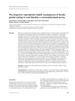
Tensile tests were performed according to ASTM E08-04 (ASTM,
2008a) to generate stress–strain curves, as shown in Fig. 3. Five
specimens of each material were prepared by wire electric discharge machining. The yield strength, ultimate tensile strength, and
overall strain were calculated from the curves. In additional to the
coatings, the ASTM A516 Gr.70 (ASTM, 2010) carbon steel substrate
was also tested in the as-received and annealed conditions.
Adhesion strength tests were performed to measure the bond
strength of the bimetallic copper–steel interface. ASTM C633-01
(ASTM, 2008b) is the standard testing method for adhesion strength
of thermal/cold spray coatings. The testing methodology involves
applying the coating to a 1 diameter plug manufactured from the
substrate material, which is bonded to a separate blank plug using
a strong adhesive bonding agent (such as epoxy). For this work, the
selected bonding agent required a curing heat treatment of ∼150 ◦ C
for 1 h.
A limitation of ASTM C633-01 testing standard is the use of a
bonding agent. Commercial high strength adhesives provide bond
strength up to 60–70 MPa before failing in the epoxy; as a result, the
test may only identify that the coating adhesion exceeds this minimum epoxy strength. To determine the actual adhesion strength, a
modified version of the ASTM E08–04 tensile test is used. A bimetallic copper–steel micro specimen, similar to those in the ASTM E8
tensile standard, were manufactured and tested using a custom
fixture, as shown in Fig. 3. Fifteen specimens for each coating were
prepared. This method allows an accurate measurement of adhesion strength, as the geometry ensures failure in the bulk copper or
at the bimetallic interface.
Three point bend tests were performed to assess ductility,
resistance to cracking, and debonding of the copper–steel composite. The testing and specimen geometry followed the guided
U-bend test in accordance with ASTM E290-09 (ASTM, 2009). The
thicknesses of the copper and steel substrate were ∼3 mm and
∼6.5 mm, respectively, for a total specimen thickness of ∼9.5 mm
(3/8 as per the standard). Five specimens were tested for each
coating type. The testing apparatus measured the force–deflection
response throughout the bend. The specimens were filmed with a
high-resolution camera during testing to determine the onset of
surface defects and debonding.
It is important to note that the three point bend test represents
an extreme loading scenario, far exceeding the container deflections and strains resulting from the DGR loads. The container’s
steel substrate and copper coating are designed to remain in the
elastic range during normal expected loadings (i.e. groundwater
hydrostatic head and bentonite swelling). Even in extreme loading scenarios, including the hydrostatic pressure from a 3000 m
thick glacier positioned over the repository would induce strains
less than 1% in the copper coating. The purpose of this beyond
design basis test is to validate the performance of the copper coating
mechanical integrity model and to ensure it can accurately predict
the coating’s behaviour including potential failure mechanisms.
2.3. Coating mechanical integrity model
2.2. Coating mechanical performance
The primary function of the copper coating is a corrosion barrier.
Nonetheless, to remain an effective barrier it must be fully dense
A coating mechanical integrity model, which can accurately
predict the behaviour of the copper–steel composite at the
bimetallic interface and in the bulk materials, is presented. The
406
C.H. Boyle, S.A. Meguid / Nuclear Engineering and Design 293 (2015) 403–412
Fig. 3. Copper coating material property testing: (A) ASTM E08-04 tensile testing, (B) ASTM C633-01 adhesion test plug specimen, (C) modified ASTM E08-04 adhesion “Dog
Bone” specimen, (D) custom test fixture for modified E08 adhesion testing.
following methodology was used to develop and validate the
model:
1. Material characterization: The individual tensile properties of the
copper coating(s) and steel substrate; as well as, the corresponding adhesion properties were experimentally determined.
2. Development of the coating mechanical integrity model: A Finite
Element Model (FEM) of the bimetallic copper–steel composite
was developed. The bimetallic interface bond is implemented
using the numerical Cohesive Zone Model (CZM) for contact/interface elements. If the failure criteria are met, the CZM
will initiate the fracture and debonding of the coating. The experimentally determined tensile and adhesion properties act as the
inputs to the model.
3. Experimental validation via three point bend testing: Using the
developed model, simulations of the three-point bend tests for
the various copper–steel specimens were completed. The computational results, including the force–deflection response and
onset of debonding, were compared to the experimental bend
tests.
CZM is a numerical fracture mechanics technique, which was
originally developed to predict crack growth in concrete but has
since been applied to other materials and failure mechanisms
(Hillerborg et al., 1976). The bilinear CZM formulation, as proposed
by Alfano and Crisfield (2001), was implemented to model debonding between the copper–steel interface and crack propagation in
the bulk copper coating. The expected container loads act normal
to the coating surface and do not create substantial shearing loads
at the bimetallic interface, therefore tangential slip will not significantly contribute to coating debonding. At this time, the tangential
slip failure criteria are assumed to be identical to normal separation (i.e. failure is Mode I dominated). The bilinear CZM constitutive
model employs a linear softening relationship between the normal cohesive contact stress and the interface separation distance
(contact gap) to simulate the debonding process.
The finite element modeling of the three-point bend test specimens, as shown in shown in Fig. 4, was completed in ANSYS V14.5
software (ANSYS). Non-linear, large deformation formulation was
used. All material properties were taken from the experiments discussed above. Isotropic strain hardening with maximum distortion
energy theory flow rule was used to model the plastic deformation
behaviour of both the copper coatings and steel substrate. Two CZM
zones were implemented: between the bimetallic interface and in
the bulk copper coating. Failure in the bulk coating theoretically
occurs at the centre of the specimen due to the high tensile loads;
Fig. 4. Three-point bend specimen geometry and cohesive zone model (CZM) interface locations.
therefore, the CZM model triggers failure if the experimental ultimate tensile strength is reached (99% of the experimental tensile
value is used to avoid numerical instability). The second CZM model
at the bimetallic interface triggers debonding if the experimental
adhesion strength is exceeded. The guided U-bend supports and
punch are manufactured from high strength steel and assumed
to be rigid in order to reduce computational effort. The punch is
loaded incrementally to a total deflection of 30 mm, identical to the
experiment, to make an approximate 90◦ bend in the specimen.
3. Results and discussion
3.1. Coating process development
Gas dynamic cold spray process development commenced with
characterizing high purity, low-oxygen copper powders. Fig. 5
demonstrates typical powder shape/size used in high pressure cold
spray (HPCS) coatings. The next phase of development optimized
various cold spray operating parameters, such as gas pressure,
pre-heating, and feed rate. These were all experimentally tested
for mechanical performance and the top performers selected. It
was determined that cost effective coatings could be produced via
two stages: initially a 50–100 m bond coat or “strike layer” was
deposited using helium as a carrier gas, followed by a bulk coating
deposited using nitrogen.
C.H. Boyle, S.A. Meguid / Nuclear Engineering and Design 293 (2015) 403–412
407
Fig. 5. Scanning election microscope analysis of cold spray copper characteristics (A) low-oxygen copper powder, (B) cross-section of fully dense test coating, (C) cross-section
depicting “Jetting” Bond.
Fig. 6. Cold spray coating on 20 diameter pipe segment (A) cold spray equipment and process, (B) machined coating, (C) section showing >3 mm fully dense copper coating.
The constant high velocity impact of particles results in a homogeneous coating, as shown in Fig. 5, with no noticeable individual
particle geometry remaining. The intimate mixing between the
copper coating and steel substrate, a process known as “jetting”,
is also visible. Jetting is a visual indication that the coating has
good adherence onto the substrate. After coating parameter optimization, the final task was to ensure feasibility of coating actual
container geometry. The technology was used to successfully coat
the pressure vessel shell material to a thickness exceeding 3 mm,
as shown in Fig. 6.
The deposited coating material strain hardens due to the
high impact velocity and bonding process. This highly cold
worked structure exhibits decreased ductility and increased
yield strength. However, material properties consistent with
polycrystalline wrought copper can be achieved by annealing
the as-deposited coating (Eason et al., 2012). Several different annealing temperatures are being evaluated within ongoing
research.
Electrodeposition process development focused on optimizing
the bath solution chemistry and the pulsed current application
to ensure a uniform, fine grained, high purity deposited copper
layer. The developed electrodeposited copper samples exhibited
high tensile strength, ductility, and adhesion. In contrast to cold
spray, no post deposition annealing is required. For this initial work
deposition rates per unit area were generally slow, with the 3 mm
coating taking approximately 72 h to produce. However, the nature
of the process allows similar deposition rates regardless of the coating area (i.e. small plates or the container can be coated in the
same time). The process is also easily scalable, making parallel
production of multiple containers possible. The technology was
Fig. 7. Electrodeposited coating on 22 diameter mock-up Mark II container section (A) electrodeposition solution tanks, (B) steel mock-up prior to immersion, (C) as-deposited
mock-up removed from tank, (D) machined mock-up with 3 mm thick copper coating.
408
C.H. Boyle, S.A. Meguid / Nuclear Engineering and Design 293 (2015) 403–412
Table 1
Tensile strength and ductility of used fuel container materials.
Specimens
Yield strength (offset 0.2%) [MPa]
Ultimate tensile strength [MPa]
Strain [%]
A516 Gr.70—as received (normalized)
A516 Gr.70—annealed 1 h@350 ◦ C
A516 Gr.70—annealed 1 h@600 ◦ C
Copper cold spray—as-deposited
Copper cold spray—annealed 1 h@350 ◦ C
Copper cold spray—annealed 1 h@400 ◦ C
Copper cold spray—annealed 1 h@600 ◦ C*
Copper electrodeposition—as-deposited
Wrought SKB OFP-copper (Sandström et al., 2009)
340.05 ± 7.24
338.09 ± 9.50
318.12 ± 1.37
N/A
103.08 ± 2.90
97.49 ± 0.90
83.56 ± 1.82
226.1 ± 4.7
∼70
511.02 ± 7.92
507.96 ± 5.20
471.53 ± 3.98
170.55 ± 14.45
198.37 ± 6.52
194.05 ± 9.77
194.91 ± 9.10
312.1 ± 6.2
∼194
24.33 ± 0.19
24.61 ± 0.51
26.69 ± 0.33
0.22 ± 0.04
23.22 ± 3.04
25.91 ± 5.71
27.08 ± 5.35
43.1 ± 5.6
∼38
*
NOTE: 2 specimens failed outside the gage length and were not considered.
used to successfully coat a mock-up Mark II container section to
a thickness exceeding 3 mm, as shown in Fig. 7.
Table 2
Adhesion strength of copper coatings.
Specimens
Adhesion strength
(modified ASTM
E8-04) [MPa]
3.2. Coating mechanical performance
Tensile properties of the various copper coatings and steel
substrates, as summarized in Table 1, were comparable to or
exceeded the reference SKB wrought copper with the exception
of the as-deposited cold spray as expected. The ductility of the
cold spray coatings varied depending on the degree of annealing.
The as-deposited samples consistently had maximum strains
of less than 0.3% resulting in immediate brittle fracture. As the
annealing temperatures increased, ductility increased while yield
strengths decreased. Large variability in maximum strain at
fracture was noted for the annealed specimens with the standard
deviation ranging from 13 to 22% of the mean. The variability in
the 600 ◦ C annealed specimens was compounded since two tests
were excluded due to failure outside the gage length. Despite the
variability, these preliminary results indicate that post-deposition
annealing can achieve strengths and ductility suitable for the
container.
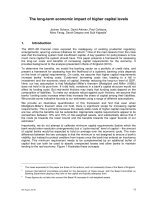
Representative stress–strain curves of the various coatings are
shown in Fig. 8. In order to demonstrate the variability of the tensile
Cold spray—as-deposited
Cold spray—annealed 1 h@350 ◦ C
Cold spray—annealed 1 h@600 ◦ C
Electrodeposition—as-deposited
83.3 ± 15.0
67.0 ± 4.8
45.9 ± 5.9
Experiment notes
Failure in bulk copper
Failure in bulk copper
Failure in bulk copper,
near steel interface
Failure in bulk copper,
necking prior to
fracture
329.8 ± 43.6
data, two curves depicting the lowest and highest achieved strains
at fracture are presented for each process (with the exception of
the low performance, as-deposited cold spray). The A516 Gr.70
steel substrate was also tested in the as-received (normalized) and
annealed conditions. The measured yield strength exceeded the
minimum 260 MPa specified by the product form standard for all
conditions. The annealed specimens had slightly lower strength but
increased ductility.
The adhesion strength testing results are summarized in Table 2
and typical specimen failures are shown in Fig. 9. The cold spray
specimens failed in the bulk coating and exhibited no yielding
Wrought Copper: RepresentaƟve SKB
350
ElectrodeposiƟon: As-deposited (Highest Strain)
ElectrodeposiƟon: As-deposited (Lowest Strain)
300
Coldspray: Annealed @ 60 0°C (Highest Strain)
Cold spray: Annealed @ 600°C (Lowest Strain)
250
Engineering Stress [MPa]
Coldspray: Annealed @ 350°C (Highest Strain)
Cold spray: Annealed @ 350°C (Lowest Strain)
200
Cold spray: As-deposited (Typical)
150
100
50
0
0
10
20
30
40
50
Engineering Strain [%]
Fig. 8. Engineering stress–strain curves of various copper coatings versus wrought copper. The results of the coating specimens with the lowest and highest strain at fracture
are shown.
C.H. Boyle, S.A. Meguid / Nuclear Engineering and Design 293 (2015) 403–412
409
Fig. 9. Typical copper coating adhesion test results: (A) cold spray as-deposited, (B) cold spray annealed (1 h@350 ◦ C), (C) cold spray annealed (1 h@600 ◦ C), (D) electrodeposition as-deposited.
before failure. The electrodeposited also failed in the bulk copper; however, significant necking occurred. This demonstrates
that the adhesion strength of the steel-copper interface likely
exceeds the ultimate tensile strength of the bulk electrodeposited
copper.
Three-point bend testing results are shown in Figs. 10–12. All
as-deposited cold spray specimens exhibited surface cracks in less
than a millimetre of loading. The cracks propagated quickly through
the bulk coating to the substrate, followed by full debonding failure
at the copper–steel bimetallic interface as observed in Fig. 10. As
loading continued, the copper coating progressively peeled away
from the substrate leaving no residual copper at the interface. The
annealed cold spray coatings performed much better, reaching 50◦
to 80◦ bend before crack formation, correlating to ∼15–28 mm
of deflection. This high variability of initial failure deflection is
discussed in Section 3.3. Once a crack developed it propagated
rapidly and debonding ensued, similar to the as-deposited cold
spray. Examination of the bimetallic interface post-failure revealed
a thin residual copper layer that remained adhered to the steel substrate. This is hypothesized to be the initial helium strike layer.
Fig. 11 shows the onset of crack formation for the 600 ◦ C samples; as
well as, full debonding at maximum bend. The 350 ◦ C samples performed similarly. The electrodeposited coating demonstrated the
best performance reaching the full 90◦ + bend without any cracking
or debonding on all five specimens; a typical results is shown in
Fig. 12.
3.3. Coating mechanical integrity model
The coating mechanical integrity model was compared to
the experimental three-point bend tests for four coatings: asdeposited cold spray, annealed cold spray (1 h@350 ◦ C), annealed
cold spray (1 h@600 ◦ C), and as-deposited electrodeposition using
the force–deflection curves and onset of cracking. Comparison of the model and experimental force–deflection curves, as
shown in Figs. 10–12, reveal good agreement. To demonstrate the
influence of the tensile property inputs, two simulations were
completed for each coating type, corresponding to the lowest
and highest strains at fracture for the tensile data experimentally
obtained.
Fig. 13 shows the good correlation between the force deflection
curve for the as-deposited cold spray samples and the FEM. The
peak force at initial crack formation ranged from 4857 to 5128 N
occurring at 0.62–0.83 mm of deflection. For the model, peak force
ranged from 4623 to 4679 N at 0.60 mm of deflection were predicted corresponding the lowest and highest tensile performance,
Fig. 10. Three-point bend results for as-deposited cold spray: (A and C) crack-initiation, (B and D) debonding at full-bend. (A and B) Experimental results versus (C and D)
model results.
410
C.H. Boyle, S.A. Meguid / Nuclear Engineering and Design 293 (2015) 403–412
Fig. 11. Three-point bend results for 600 ◦ C annealed cold spray: (A and C) crack-initiation, (B and D) debonding at full-bend. (A and B) Experimental results versus (C and
D) model results.
Fig. 12. Three-point bend results for as-deposited electrodeposition: no debonding at full bend (A) experimental result versus (B) model results.
Fig. 13. Three-point bend force–deflection response: as deposited cold spray.
respectively. After debonding began, the model’s predicted force
response falls within the range of experimental results, as shown
in Fig. 13. At full bend, the experimental and model peak forces
ranged from 7408 to 7741 N.
As previously mentioned, the annealed cold spray specimens
showed the largest variability terms in performance, as reflected
in Figs. 14 and 15. For the 350 ◦ C annealed specimens, all yielded
at approximately ∼4500 N and 1 mm of deflection, then had
a similar response up to 15 mm of deflection. Specimens then
failed at 16–24 mm of deflection, with final peak forces between
8172 and 8745 N. The model predicted crack initiation at ∼13.5
and 20.4 mm for lowest and highest strain tensile data, respectively.
For the 600 ◦ C annealed specimens, all yielded at approximately
∼4100 N and 1 mm of deflection, then had a similar response up to
15 mm of deflection. A total of three specimens failed between 15
and 18 mm and the final two failed at 20 mm and 27 mm, as can
be observed in Fig. 15. For the four specimens that failed between
15 and 20 mm, the final peak force was 7149–7268 N. The model
predicted crack initiation at ∼16.5 mm for the lowest strain tensile data, followed by rapid propagation and coating debonding.
The final peak force was 7156 N, which is within the range of the
experimental results. For the highest strain tensile data, the model
predicted no coating failure; however, the resulting peak strain is
within 5% of the ultimate strain and is close to failure. It is hypothesized that inhomogeneities inherent to the cold spray process act
C.H. Boyle, S.A. Meguid / Nuclear Engineering and Design 293 (2015) 403–412
10000
9000
8000
Force [N]
7000
6000
5000
Cold spray: Annealed (1hr @ 350°C)
4000
3000
2000
1000
0
0
3
6
9
12
15
18
21
24
27
30
DeflecƟon [mm]
Fig. 14. Three-point bend force–deflection response: annealed (1 h@350 ◦ C) cold
spray.
10000
9000
7000
Force [N]
strain is within 3–11% of predicted failure. For the final 3 mm of
loading, the experimental specimen’s peak force increased substantially to 14,920–15,983 N; whereas, the model’s near linear increase
resulted in a peak force of 13,748–13,919 N. The reason for this rise
is unknown.
In summary, the results confirm that the modeling can
accurately predict the behaviour of the copper–steel composite
including failure at the bimetallic interface. The predicted failure mechanisms, final deformed geometries, and force–deflection
curves were consistent with the experimental results, as shown
in Figs. 13–16. The annealed cold spray results showed high variability in the tensile testing; as a result, the three-point bend tests
produced a wide range of failures. Cold spray process optimization
is still ongoing and fabrication variability continues to be reduced.
As previously mentioned, it is important to note that preliminary
UFC design analysis has shown the copper strains would be much
less than 1% even under the glacial loading scenario. Even the worst
performing annealed cold spray coating test specimens exceeded
20% strain and would be at no risk of failure. The three point bend
loadings represent a beyond design basis scenario with induced
strains approaching 28% at full bend.
4. Conclusion
8000
6000
5000
4000
3000
2000
1000
0
0
3
6
9
12
15
18
21
24
27
30
DeflecƟon [mm]
Fig. 15. Three-point bend force–deflection response: annealed (1 h@600 ◦ C) cold
spray.
18000
16000
14000
12000
Force [N]
411
10000
8000
6000
4000
2000
0
0
3
6
9
12
15
18
21
24
27
30
DeflecƟon [mm]
Fig. 16. Three-point bend force–deflection response: as deposited electrodeposition.
as stress risers and are enough to initiate localized failure zones not
captured in the model.
For the electrodeposited specimens, yielding occurred at
∼6000 N and subsequent loading produced no failures of the coating for all specimens, as shown in Fig. 16. The model also predicted
no failure using both the lowest and highest strain tensile data
and followed the experimental force–deflection response within 4%
up to 27 mm of deflection. Although no cracking occurs, the peak
The experimental development and mechanical modeling of
a robust copper coating for use as a Used Fuel Container corrosion barrier has been presented. Cold spray and electrodeposition
coatings with comparable mechanical performance to wrought
copper have been fabricated on the full-scale container materials.
The mechanical performance of the annealed cold spray and as
deposited electrodeposition coatings were comparable or exceeded
that of the reference wrought copper and are suitable for the container design. Variability in the performance of cold spray coatings
was noted. This work represents only the initial “proof of concept”
results; as part of future work, additional process refinements and
research into alternative annealing schedules will be completed to
reduce this variability and improve overall performance.
A mechanical integrity model for the copper–steel composite was developed and experimentally validated. It accurately
predicted the various copper coating responses, including the
bimetallic interface failure. The model’s average force response
deviated less than 4% from the experiments, with localized
maximums of approximately 10–15%. For future work, this model
will be used to evaluate the performance of the coatings on the
Mark II UFC under repository loading conditions; as well as, beyond
design basis analyses to demonstrate the conservativeness of the
design.
In conclusion, this work demonstrates that copper coatings
can be reliably fabricated on container materials and geometries. These coatings have been extensively tested and confirm
ample mechanical performance for container design. We can accurately model their response under expected repository conditions
and beyond. Production of full-scale containers, additional optimization of coating parameters, and application of the model to
container geometries are currently underway.
Acknowledgments
Coating process development, optimization, and experimental
work has been conducted in collaboration with Integran Technologies Inc. and the National Research Council Canada facilities.
References
Alfano, G., Crisfield, M.A., 2001. Finite element interface models for the debonding
analysis of laminated composites: mechanical and computational issues. Int. J.
Numer. Methods Eng. 50, 1701–1736.
412
C.H. Boyle, S.A. Meguid / Nuclear Engineering and Design 293 (2015) 403–412
ANSYS® Mechanical, Release 14.5. Help System, Workbench. ANSYS Inc., Canonsburg, PA. />ASTM, 2008a. Standard test methods for tension testing of metallic materials. In:
ASTM E8/E8M-08. ASTM International, West Conshohocken, PA.
ASTM, 2008b. Standard test method for adhesion or cohesion strength of thermal
spray coatings. In: ASTM C633-01. ASTM International, West Conshohocken, PA.
ASTM, 2009. Standard test methods for bend testing of material for ductility. In:
ASTM E290-09. ASTM International, West Conshohocken, PA.
ASTM, 2010. Standard specification for pressure vessel plates, carbon steel, for
moderate- and lower-temperature service. In: ASTM A516/516M-10. ASTM
International, West Conshohocken, PA.
Aust, K., Brooks, I., Gonzalez, F., Lin, P., Palumbo, G., Tomantschger, K., Nagarajan, N., 2008. Method for preparing polycrystalline structures having improved
mechanical and physical properties. Canadian Patent No. 2674403.
Chastain, M.L., Deymier-Black, A.C., Kelly, J.E., Brown, J.A., Dunand, D.C., 2011. Metallurgical analysis of copper artifacts from Cahokia. J. Archit. Sci. 38, 1727–1736.
Choi, H.J., Lee, M., Lee, J.Y., 2010. Application of a cold spray technique to the fabrication of a copper canister for the geological disposal of CANDU spent fuels.
Nucl. Eng. Des. 240 (10), 2714–2720.
Eason, P.D., Kennett, S.C., Eden, T.J., Krull, I., Kowalski, B., Jones, J.L., 2012. In situ
observation of microstrain relief in cold-sprayed bulk copper during thermal
annealing. Scr. Mater. 67, 791–794.
Hillerborg, A., Modeer, M., Petersson, P-E., 1976. Analysis of crack formation and
crack growth in concrete by means of fracture mechanics and finite elements.
Cem. Concr. Res. 6, 773–782.
Irissou, E., Legoux, J.-G., Ryabinin, A., Jodoin, B., Moreau, C., 2008. Review on cold
spray process and technology: Part I. Intellectual property. J. Therm. Spray Technol. 17, 495–516.
Jakupi, P., Keech, P.G., Barker, I., Ramamurthy, S., Jacklin, R.L., Shoesmith, D.W.,
Moser, D.E., 2015. Characterization of commercially cold-sprayed and electrodeposited copper grains on mild steel. J. Nucl. Mater. 466, 1–11.
Keech, P.G., Vo, P., Ramamurthy, S., Chen, J., Jacklin, R., Shoesmith, D.W., 2014. Design
and development of copper coatings for long term storage of used nuclear fuel.
Corros. Eng. Sci. Technol. 49, 425 (Special Issue on Corrosion in Nuclear Waste
Systems).
King, F., 1995. A natural analogue for the long-term corrosion of copper nuclear
waste containers—reanalysis of a study of a bronze cannon. Appl. Geochem. 10,
477–487.
Kwong, G.M., 2011. Status of corrosion studies for copper used fuel containers
under low salinity conditions. In: NWMO Technical Report, NWMO-TR-2011-14.
Nuclear Waste Management Organization, Toronto, Canada.
Miller, W.M., Chapman, N., McKinley, I., Alexander, R., Smellie, J.A.T., 1994. Natural Analogue Studies in the Geological Disposal of Radioactive Wastes. Elsevier
Science, Amsterdam, The Netherlands.
NWMO, 2005. Choosing a Way Forward: The Future Management of Canada’s Used
Nuclear Fuel. Nuclear Waste Management, Toronto, Canada.
Papyrin, A., Kosarev, V., Klinkov, S., Alkhimov, A., Fomin, V.M., 2006. Cold Spray
Technology. Elsevier, Amsterdam, The Netherlands.
Petterson, K., 2012. A review of the creep ductility of copper for nuclear waste canister application. In: SSM Technical Note 2012:13. Strålsäkerhetsmyndigheten,
Stockholm, Sweden.
Raiko, H., Sandström, R., Rydén, H., Johansson, M., 2010. Design analysis report for
the canister. In: SKB Technical Report TR-10-28. Svensk Kärnbränslehantering
AB, Stockholm, Sweden.
Sandström, R., Hallgren, J., Burman, G., 2009. Stress Strain flow curves for Cu-OFP.
In: SKB Rapport R-09-14. Svensk Kärnbränslehantering AB, Stockholm, Sweden.
Scully, J.R., Edwards, M., 2013. Review of NWMO copper corrosion allowance. In:
NWMO Technical Report, NWMO-TR-2013-04. Nuclear Waste Management
Organization, Toronto, Canada.
Stroes-Gascoyne, S., Hamon, C.J., Maak, P., Russell, S., 2010. The effects of the physical
properties of highly compacted smectitic clay (bentonite) on the culturability of
indigenous microorganisms. Appl. Clay Sci. 47, 155–162.
Svensk Kärnbränslehantering AB, 2010. Design and production of the KBS-3 repository. In: SKB Technical Report TR-10-12. Svensk Kärnbränslehantering AB,
Stockholm, Sweden (updated 2013-10).
Wolfaardt, G.M., Korber, D.R., 2012. Near-field microbiological considerations relevant to a deep geological repository for used nuclear fuel-state of science review.
In: NWMO TR-2012-02. Nuclear Waste Management Organization, Toronto,
Canada.