Purification of a GalNAc-cluster-conjugated oligonucleotide by reversed-phase twin-column continuous chromatography
Bạn đang xem bản rút gọn của tài liệu. Xem và tải ngay bản đầy đủ của tài liệu tại đây (1.72 MB, 8 trang )
Journal of Chromatography A 1663 (2022) 462734
Contents lists available at ScienceDirect
Journal of Chromatography A
journal homepage: www.elsevier.com/locate/chroma
Purification of a GalNAc-cluster-conjugated oligonucleotide by
reversed-phase twin-column continuous chromatography
Richard Weldon b, Jörg Lill a, Martin Olbrich a, Pascal Schmidt a, Thomas Müller-Späth b,∗
a
b
F. Hoffmann-La Roche Ltd., Grenzacherstrasse 124, CH-4070 Basel, Switzerland
ChromaCon AG, Technoparkstr. 1, CH-8005 Zurich, Switzerland
a r t i c l e
i n f o
Article history:
Received 18 October 2021
Revised 1 December 2021
Accepted 2 December 2021
Available online 12 December 2021
Keywords:
Oligonucleotide
Purification
MCSGP
Continuous manufacturing
Scale-up
a b s t r a c t
Multicolumn Countercurrent Solvent Gradient Purification (MCSGP) is a continuous chromatography technique used to maximize purification yields compared to traditional batch purification methods. Here we
apply MCSGP for the reversed phase purification of a N-acetylgalactosamine (GalNAc)-cluster-conjugated
DNA-LNA gapmer oligonucleotide therapeutic using a twin-column chromatography system. Based on a
batch process as a starting point, MCSGP was designed, optimized and compared with the batch process regarding process performance and scale-up requirements. Product yields increased from 52.7% using
batch chromatography to 91.5% using MCSGP, with purity, productivity, and buffer consumption otherwise
comparable. In a manufacturing scenario, use of MCSGP would allow the downscaling of oligonucleotide
synthesis by 42.5%, which would result in a significant cost reduction and increased throughput. Moreover, the equipment, chemicals and methodology used in MCSGP are analogous to a standard reversed
phase purification allowing for a “like for like” transition to the upgraded MCSGP process.
© 2021 The Authors. Published by Elsevier B.V.
This is an open access article under the CC BY-NC-ND license
( />
1. Introduction
1.1. Chromatographic purification of oligonucleotides
Oligonucleotide compounds are emerging as a major category
of therapeutic drugs, due to their ability to regulate gene expression with great specificity. Native oligonucleotide sequences
are naturally vulnerable to degradation and clearance by the immune system, and they also fail to permeate through cell membranes to the site of biological action. Recent advances have led to
the development of synthetic oligonucleotides modified with nucleic acid analogues that greatly enhance stability and avoid clearance by the immune system [1]. In addition, conjugation with
N-acetylgalactosamine (GalNAc) ligands provides a mechanism for
transport of synthetic oligonucleotides into hepatocytes via endocytosis allowing for the development of treatments that target diseases of the liver [2].
Based on these recent advances in the pharmacological properties of oligonucleotide therapeutics, there is now an increasing
∗
Corresponding author at: ChromaCon AG, Technoparkstrasse 1 8005 Zurich,
Switzerland.
E-mail address: (T. Müller-Späth).
pipeline of oligonucleotide drugs in clinical trials and demand for
production capacity is rapidly expanding [3]. However, oligonucleotide therapeutics are yet to be manufactured at multi-ton
scale and no compounddedicated production facilities exist. Given
that oligonucleotide production at larger scale is on the horizon,
pharmaceutical companies and CMOs are actively evaluating platform technologies that will optimize production and reduce costs.
Oligonucleotide production is done in four major steps, solid phase
oligonucleotide synthesis, chromatographic purification, desalting
by diafiltration or precipitation and finally isolation by freeze drying [4]. Currently, oligonucleotide synthesis is the major cost driver
in production of therapeutic oligonucleotides and any loss of product in the downstream steps has a major impact on the overall
manufacturing costs. In particular, the preparative chromatographic
purification is a critical step where product losses can be substantial and should therefore be thoroughly optimized.
The goal of the chromatographic purification step is to achieve
a clinical grade product purity specification of >90%, which is typically associated with a yield loss between 20% and 50%, and expensive re-chromatography steps to recover product from the sidefractions. Given the diminishing returns of re-chromatography, the
upstream oligonucleotide synthesis needs to be scaled up to compensate for the overall yield loss during the chromatographic purification.
/>0021-9673/© 2021 The Authors. Published by Elsevier B.V. This is an open access article under the CC BY-NC-ND license ( />
R. Weldon, J. Lill, M. Olbrich et al.
Journal of Chromatography A 1663 (2022) 462734
The chromatographic purification of oligonucleotides is challenging, because the synthesis delivers about 60% to 80% desired
product together with a mixture of impurities such as shortmers
(e.g. N-x), derived from incomplete chemical coupling reactions,
full-length product impurities (e.g. cyanoethyl modification, phosphate impurity, depurination), derived from modifying side reactions, and longmers (e.g., lambdamers, branchmers), derived from
the incorporation of impurities found in the starting raw materials [5]. Even with considerable optimization efforts, a preparative batch method gives a chromatogram with an elution profile
in which impurities are significantly co-eluting with the product,
especially for highly phosphorothiolated sequences. Impurities that
are chemically very similar to the desired product tend to co-elute.
N-1 impurities missing one nucleotide, and N + 1 impurities with
one additional nucleotide are examples of impurities that are particularly challenging to remove. To meet the product specification,
it is therefore essential to carefully fractionate the pure material
from the elution peak. Side fractions with lower purity are either
discarded or undergo re-chromatography at great cost (lower productivity, increased buffer consumption, intermediate sample storage capacity, additional quality control steps, etc.).
As with any conventional batch chromatographic methods,
there is an inverse relationship between product purity and yield
depending on separation performance, how the elution peak is
fractionated, and product is pooled (Fig. 1A). Overcoming the yield
/ purity tradeoff can be achieved using recycling chromatography
or more advanced twin column-based process technology, such as
MCSGP. MCSGP alleviates the yield / purity trade-off by internally
recycling the impure product side-fractions to a second column
ensuring that only the product reaching the purity specification
leaves the system (Fig. 1B). The recycling in the MCSGP process
and in single-column based recycling processes such as Steadystate recycling (SSR) and Closed-loop recycling (CLR) is fundamentally different [6–8]. In the latter two processes the chromatographic profile passes through a pump every cycle which is possibly detrimental to product stability and limits the processes to
isocratic operation. In MCSGP, impure side fractions that are recycled from one column to the other are fully adsorbed on the
second column and then subject to renewed gradient elution to
restart the separation. Product and impurities only pass through a
pump during the load step, which is beneficial to product stability. This makes MCSGP well suited for the separation of complex
molecules such as oligonucleotides. While originally developed as a
multicolumn process with 3–6 columns [9,10], over the years MCSGP was simplified to a twin column process, greatly increasing
operational flexibility, and reducing complexity. The experimental
design of twin column MCSGP is described in detail in [11].
•
•
•
•
At the conclusion of switch 1, both columns are immediately
ready for switch 2. Column 2 is now fully loaded and column 1
requires cleaning and regeneration. P1 – P4 are repeated as described above, but with column positions interchanged (Fig. 1C yellow arrows). By alternating the position of column 1 and column 2 switch-to-switch, MCSGP can operate continuously. Finally,
1 cycle of MCSGP is defined as 2 switches that includes 1 product
elution from each column.
MCSGP has been successfully applied to the purification of peptides, proteins, and DNA-based oligonucleotides [12–15]. Here we
evaluate for the first time the application of MCSGP for the purification of a GalNAc-cluster-conjugated DNA-LNA gapmer oligonucleotide using reversed phase chromatography. We demonstrate a
major improvement in yield by substituting single column batch
chromatography for MCSGP and provide process performance predictions for production at industrial scale.
2. Methods
2.1. Oligonucleotide synthesis and crude preparation
The oligonucleotide KGN.Lo.dCo.dAo.lTs.lEs.lAs.dAs.dCs.dTs.dTs.
dTs.dCs.dAs.dCs.dTs.dTs.lEs.lAs.lG (KGN = Bislysin GalNAc cluster;
Sequence description: first letter: d = DNA, l = LNA; second letter: A = adenine, C = cytosine, E = 5-methylcytosine, G = guanine,
L = linker, T = thymine; third letter: o = phosphate, s = thiophosphate) was synthesized using standard phosphoramidite chemistry
on solid phase followed by ultrafiltration and solution phase conjugation to the GalNAc cluster. The solid phase synthesis was performed at a scale of 2.0 mmol using an ÄKTA Oligopilot 100
and Primer Support Unylinker (NittoPhase LH Unylinker 400). In
general, 1.5 equivalents of the phosphoramidites (0.2 M in acetonitrile or acetonitrile/dichloromethane = 1/1) were employed.
All reagents were used as received from commercially available
sources and reagent solutions at the appropriate concentration
were prepared:
1.2. The MCSGP process principle
MCSGP can be systematically designed with the aid of software
by dividing a batch gradient chromatogram into four phases (P1P4) making up one MCSGP “switch”. A step-by-step depiction of
the MCSGP process principle is outlined in Fig. 1C. The table shows
process steps occurring simultaneously for “column 1” and “column 2” during an MCSGP switch and this is aligned with an example UV trace for column 1, which undergoes product elution during the switch. The table shows the initial state of both columns at
t = 0 and the four MCSGP phases:
•
P1 (Columns in parallel) - elution of weakly adsorbing impurities (W) from column 1 to waste; simultaneous regeneration of
column 2 ready for loading steps in P2, P3 and P4.
P2 (Columns interconnected for side fraction recycling) – elution of weakly adsorbing impurities + product (W/P) from column 1, recycled with in-line dilution directly to column 2
P3 (Columns in parallel) – elution and collection of pure product (P) from column 1; simultaneous loading of new feed on
column 2. To maintain a switch-to-switch steady state, the
quantity of new feed applied is in equilibrium with product (P)
removed. The load required to achieve this is calculated with
the aid of software, based on the batch chromatogram and fraction analysis.
P4 - (Columns interconnected for side fraction recycling) elution of product + strongly adsorbing impurities (P/S) from column 1, recycled with in-line dilution directly to column 2
•
•
•
•
•
Initial state – Column 1 is fully loaded during a “startup”
method run before the switch or from the previous switch in
the MCSGP run; Column 2 requires cleaning and regeneration
to remove strongly adsorbing impurities (S) carried over from
a prior switch or at the very start of an MCSGP run column 2
would be clean.
•
•
activator: 1.0 M 4,5-dicyanoimidazole, 0.1 M N-methylimidazole
in acetonitrile
thiolation: 0.1 M xanthan hydride in acetonitrile/pyridine = 1/1
v/v
oxidation: 0.05 M I2 in pyridine/water = 9/1 v/v
detritylation: 10 vol% 2,2-dichloroacetic acid in toluene
capping A: 10 vol% N-methylimidazole, 10 vol% 2,6-lutidine in
acetonitrile
capping B: 20 vol% acetic anhydride in acetonitrile
backbone deprotection: 20 vol% diethylamine in acetonitrile
Cleavage and deprotection was achieved using 30 wt% aqueous ammonium hydroxide/ethanol = 3/1 v/v for 9 h at
2
R. Weldon, J. Lill, M. Olbrich et al.
Journal of Chromatography A 1663 (2022) 462734
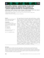
Fig. 1. Introduction to MCSGP. (W) = weakly adsorbing impurities (blue), (P) = product (red), (S) = strongly adsorbing impurities (green), (W/P) = mixture of product
and weakly adsorbing impurities, (P/S) = mixture of product and strongly adsorbing impurities. A – Conventional center-cut batch purification produces side fractions of
insufficient product purity for pooling leading to product losses; B – By contrast, MCSGP has automatic recycling of side fractions to greatly reduce product losses; C – MCSGP
Process Principle showing 1 MCSGP “switch”. P1 = phase 1, P2 = phase 2, P3 = phase 3, P4 = phase 4. Columns are operated in parallel during P1 and P3; Columns are
interconnected for product recycling in P2 and P4. The position of the columns alternates from switch to switch allowing for continuous operation (yellow arrows indicate
column interchange between switches).
55 °C to give the crude, unconjugated oligonucleotide. Removal of excess ammonia, concentration and exchange of the
counterion was achieved by ultrafiltration followed by diafiltration against aqueous sodium chloride and water using a
Sartoflow ultrafiltration system with 2 kDa Hydrosart membrane (Sartorius). The intermediate was isolated by precipitation with ethanol. For the conjugation reaction, GalNAc acid
(1.4 equiv.) was dissolved in N,N-dimethylformamide and activated by addition of 2-(5-Norbornene-2,3-dicarboximido)−1,1,3,3tetramethyluronium tetrafluoroborate (TNTU) (1.4 equiv.). This
mixture was added to a solution of the precipitate at 20 wt% in
0.1 M aqueous sodium bicarbonate (pH 8.3). The resulting mixture
was stirred for 2 h at ambient temperature after which the title
compound was obtained with 77.5 area% purity by RP-HPLC. The
crude solution was directly used for purification.
2.2. Batch and MCSGP chromatography
A preparative batch method was carried out as a performance
benchmark for comparison to MCSGP as well as to serve as the
design template for MCSGP. Batch and continuous chromatography
were carried out using the Contichrom CUBE 30, a twin column
system for continuous chromatography (ChromaCon AG, A YMC
Company). An external column thermostat (Knauer), fitted with
two heat exchange cartridges was set to 45 °C and used for all
experiments. UV absorbance at 300 nm was recorded by the inter3
R. Weldon, J. Lill, M. Olbrich et al.
Journal of Chromatography A 1663 (2022) 462734
Table 1
Materials – Batch vs. MCSGP.
Process
Material
Description
Batch
Column
Mobile phase A
Mobile phase B
Regeneration buffer
Feed composition
Feed purity
YMC Triart Prep C8-S (150 × 10 mm ID, S-10 μm, 12 nm)
5 vol% acetonitrile (Merck, 1.00030) / 95 vol% 0.2 M sodium acetate (Sigma-Aldrich, 1.06267) in water
30 vol% acetonitrile / 70 vol% 0.2 M sodium acetate
78 vol% acetonitrile / 22 vol% 0.2 M sodium acetate
The synthesis crude was diluted with mobile phase A to a final concentration of 4.5 g/L
77.5%
MCSGP
Column
Mobile phase A
Mobile phase B
In-line dilution buffer
Feed composition
Feed purity
2x YMC Triart Prep C8-S (150 × 0.46 mm ID, S-10 μm, 12 nm)
5 vol% acetonitrile / 95 vol% 0.2 M sodium acetate in water
15 vol% acetonitrile / 85 vol% 0.2 M sodium acetate
0.2 M sodium acetate in water
The synthesis crude was diluted in mobile phase A to a final concentration of 2.19 g/L
77.5%
Table 2
Process parameters overview - Batch vs. MCSGP.
Parameters
Units
Batch process
MCSGP
Run/Cycle time
Column Temperature
Equilibration (P1)
Equilibration (P1)
Equilibration (P1)
Load (Crude) (P3)
Loading (Crude) (P3)
Loading (Crude) (P3)
Wash after load
Wash after load
Wash after load
Gradient Start (P1)
Gradient End (P4)
Gradient duration (P1 – P4)
Gradient flow rate (P1 – P4)
In-line dilution flow rate (P2)
In-line dilution flow rate (P4)
Regeneration
Regeneration
Regeneration
Re-equilibration
Re-equilibration
[min]
[ °C]
[% ACN]
[CV]
[cm/h]
[g/L resin]
[CV]
[cm/h]
[% ACN]
[CV]
[cm/h]
[% ACN]
[% ACN]
[CV]
[cm/h]
[cm/h]
[cm/h]
[% ACN]
[CV]
[cm/h]
[CV]
[cm/h]
47.3
45
7.5
1.84
238
2.52
0.56
238
5.0
0.79
238
7.5
15
3.47
142
–
–
78
1
238
1.84
238
58.9
45
5.0
2.00
150
1.82
1.67
254
–
–
–
7.7
12.9
3.82
142
198
240
–
–
–
–
–
with a flow rate of 0.4 mL/min. Detection was carried out at
260 nm. Mobile phase A was composed of 200 mM 1,1,1,3,3,3Hexafluoro-2-propanol (Sigma-Aldrich, 105,228)/5 mM hexylamine
(Sigma-Aldrich, 219,703)/4 mM triethylamine (Sigma-Aldrich,
65,897)/0.004 vol% phosphoric Acid (Sigma-Aldrich, 79,606). Mobile phase B was composed of 10 vol% acetonitrile/90 vol% MeOH
(Merck 1.06007). Supplemental Table 3 details gradient parameters
used in the method. Samples from the batch & MCSGP fractions
were prepared for HPLC analysis by diluting 3-fold with 90 vol%
water/10 vol% mobile phase B.
All oligonucleotide concentration measurements were done using a Nanodrop Lite (Thermo Scientific).
3. Results and discussion
A prerequisite for the development of the MCSGP process was
the generation of a batch purification process which serves as the
MCSGP design starting point as well as a benchmark for process
performance comparisons. Since many performance parameters of
the batch process are carried over into MCSGP, the batch process
should minimally reach the desired target purity threshold, achieve
good productivity, and have acceptable buffer consumption. Due
to the internal recycling in MCSGP, optimization with respect to
yield can be achieved just by adapting a batch process to MCSGP.
A batch process with a yield between 20% and 80% is typically a
good starting point for MCSGP development.
Fig. 2A shows the UV trace (UV1@300 nm) and % mobile phase
B vs. time [min] for the benchmark batch purification run (run parameters are outlined in Tables 1 and 2). A load of 2.52 g/L resin
was used (higher loads lead to insufficient product purity, data
not shown). Fractions from the product elution were analyzed by
HPLC to determine%area product purity (Fig. 2B), and using a Nanodrop to measure total oligonucleotide concentration (g/L). Product
and impurity concentrations were calculated as % area abundance
in the sample multiplied by the total oligonucleotide concentration (Fig. 2C). Benchmark process performance was then calculated
for the pool of fractions with an aggregate purity of 94.22 area%
(Fig. 2B, horizontal dotted line = 94% purity threshold), giving a
yield of 52.7%, a productivity of 1.3 g/L/h and buffer consumption
of 9.59 L/g (Table 3).
The adaptation of the benchmark batch process to MCSGP was
facilitated with design software (“MCSGP wizard”). The wizard determines the operating parameters for MCSGP (i.e., gradient concentration and flow rates). The UV trace for the batch run (Fig. 2A),
along with data for fraction purity (Fig. 2B) and product concentration (Fig. 2C) were imported into the MCSGP wizard and overlayed.
Phase boundaries (P1 – P4) were set as detailed in the legend of
Fig. 2. P3 was positioned to achieve a target purity of >94 area%
(calculated by the wizard), P2 & P4 were positioned to fully recycle
nal CUBE 30 UV detectors located directly after each column outlet (UV1@300 nm and UV2@300 nm respectively). Table 1 details
the column characteristics, buffer composition and feed composition used for batch and MCSGP runs. Table 2 gives an overview
of the method parameters used for batch vs. MCSGP runs. Supplemental Table 1 & 2 detail the specific method parameters used to
run batch and MCSGP with the Contichrom CUBE system.
Upon first use, the columns were conditioned for 10 h in Regeneration buffer (6 CV at 9 cm/h). Before starting batch and MCSGP
runs, columns were further equilibrated with 6 CV mobile phase A
at 45 °C (238 cm/h).
Two notable modifications to the batch method were made for
MCSGP:
•
•
The “wash after loading” step was excluded (The strong recycling step effectively substitutes the wash after load step).
The Regeneration step was applied only at the end of the MCSGP run and not after every elution like in batch (no negative
impact on MCSGP process performance was evident).
2.3. Analytics
Analytical HPLC chromatography was carried out using Agilent 1290 Series at 80 °C. An Acquity UPLC Oligonucleotide
BEH C18, 50 × 2.1 mm; (1.7 μm) column (Waters) was used
4
R. Weldon, J. Lill, M. Olbrich et al.
Journal of Chromatography A 1663 (2022) 462734
Fig.. 2. A to D - Batch run chromatographic profiles with fraction analysis. Product purity measured by HPLC analysis (area%) and concentration by Nanodrop (g/L). Each dot
represents an analyzed fraction. A – Plot showing absorbance UV1@300 nm &%B modifier concentration; B – Plot showing absorbance UV1@300 nm &%area product purity;
C – Plot showing absorbance UV1@300 nm & product and impurity concentrations (g/L); D – Plot showing absorbance UV1@300 nm &%area impurities N-1 & N + 1. The
gradient is split into 4 phases; P1 (W) is the region (gray highlight) containing weakly adsorbing impurities (directed to waste in MCSGP process); P2 (W/P) is the region (blue
highlight) with a mixture of product and weakly adsorbing impurities (internal recycling in MCSGP process); P3 (P) is the region (red highlight) with product that achieves
purity specification (product elution in MCSGP process); P4 – (P/S) is the region (green highlight) with a mixture of product and strongly adsorbing impurities (internal
recycling in MCSGP process). Section boundaries P1 to P4 were used to guide MCSGP design. E & F – MCSGP chromatographic profiles showing absorbance UV1@300 nm
plotted vs. time [min], red lines indicate UV signals from column 1 and blue lines indicate elution from column 2. Dotted black line indicates%B modifier concentration. E –
Plot showing 6 consecutive MCSGP cycles with 12 product elutions; F – Plot showing an overlay of 6 consecutive MCSGP cycles. Colors indicate phases as described in Fig. 2.
side fractions of lower product purity. When setting the product
collection window, it was also important to check the abundance
of two critical synthesis impurities (N-1 and N+1). Due to their
structural similarity to the target oligonucleotide, these impurities
are challenging to remove so it was important to optimally position the product collection window to minimize them (Fig. 2D).
Next, the MCSGP wizard calculated the in-line dilution flow
rates necessary to dilute the%B modifier concentration of the eluent back to initial loading conditions (Table 2). This is essential so
that as product is recycled from column 1 to column 2, the product can be fully re-adsorbed. Lastly, the loading parameters needed
to establish a cyclic steady state were also calculated by the MC5
R. Weldon, J. Lill, M. Olbrich et al.
Journal of Chromatography A 1663 (2022) 462734
Table 3
Process performance metrics – Batch vs. MCSGP.
Parameters
Units
Bed height
Loading flow rate
Elution flow rate
Washing, cleaning flow rate
Product purity
Impurity N-1
Impurity N + 1
Yield
Product concentration
Productivity
Load/cycle (Crude)
Startup load (Crude)
Buffer cons.
[cm]
[cm/h]
[cm/h]
[cm/h]
[%]
[%]
[%]
[%]
[g/L]
[g/L/h]
[g/L]
[g/L]
[L/g]
Feed
77.48
3.36
4.23
Batch process
MCSGP
15
238
142
238
94.22
0.93
1.22
52.70
3.25
1.30
2.52
N/A
9.59
2 × 15
254
142
150
94.16
0.87
1.41
91.58
2.71
1.33
1.83
2.44
9.22
conclude that, with respect to product quality, the MCSGP process
parameters are well designed. Fig. 3C & D show analytical chromatograms of the final MCSGP product pool (red) for all 6 cycles
relative to the input feed material (black) achieving an enrichment
of product from 77.5 area% to 94.2 area% purity. Table 3 provides
a detailed overview of MCSGP vs. batch process performance for a
>94 area% purity specification.
Fig. 3E shows a yield vs. purity curve for the batch run compared to the MCSGP operating point. The curve was constructed
starting with a data point for the purest fraction with lowest yield.
Each additional data point was generated by adding neighboring
fractions and recalculating yield and purity until all fractions were
included. Fig. 3E demonstrates how the yield / purity tradeoff of
the batch process has been overcome in MCSGP, with an operating point in the upper right corner. For equivalent purity, MCSGP outperformed the batch process with respect to yield, 92% vs.
53%, achieving almost complete recovery of the input material (excluding performance impact of “Startup” and “Shutdown” methods). Productivity and buffer consumption of the MCSGP process
(1.3 g/L resin/h and 9.2 L/g respectively) were both comparable to
the batch process (1.3 g/L resin/h and 9.6 L/g respectively). The
load of MCSGP was not optimized and lower than the load value
of batch chromatography (1.8 L/g vs. 2.5 L/g). Although load optimization in general was not a part of this study, it was qualitatively
determined in batch experiments that small increases in load lead
to a further loss in yield, indicating that the binding capacity of
the resin was utilized to a great extent. Product concentration was
17% lower in MCSGP so there remains scope for improvement in
the method to reduce eluate volumes.
Table 4 shows example scale-up scenarios for the batch and
MCSGP processes. Equipment and resin requirements were determined for the reference batch process with a feed input of
3.2 kg/day resulting in product output of 1.3 kg/day, using a single
60 cm inner diameter (ID) column. Two MCSGP setups were compared, the first is designed to process the same input of 3.2 kg/day
of feed and the second is designed to produce the same output of
1.3 kg/day of product.
The first MCSGP setup can be exploited to produce 73.6% more
product (2270 g/day in MCSGP vs. 1307 g/day in batch) from same
quantity of feed material (3200 g/day) or alternatively one can
produce the same amount of product, but 42.5% faster with MCSGP. In this scenario, MCSGP would use two columns of 60 cm
(ID). Obviously, using the same total resin volume, a batch process
could deliver 2614 g/day of product, but with the requirement of
2 × 3200 g/day = 6400 g/day feed.
In the second MCSGP setup, 1.3 kg/day of product can be produced from 42.5% less feed allowing the synthesis to be downscaled by 42.5%. In this comparison, the Batch and MCSGP processes use the same total amount of resin. In this scenario, MCSGP
would use two columns of 45 cm ID. The smaller column inner
diameter allows use of smaller pump sizes on the skid to obtain
the desired linear flow rate of the eluents. Given that MCSGP uses
similar equipment with a comparable footprint as a batch chromatography, it is feasible to equip existing facilities.
In addition to improving yields, there are other advantages of
MCSGP compared to batch chromatography.
SGP wizard. Once the design procedure was complete, the MCSGP
wizard created 3 methods to be run as a procedure:
•
•
•
Method 1 was the “Startup” method where the upstream column is pre-loaded with feed like the batch process.
Method 2 was the main method consisting of 6 cycles of MCSGP.
Method 3 was a “Shutdown” method consisting of 1 switch
with final product elution, but without feeding.
In comparison to the cyclic steady state of MCSGP, the combined performance impact of the “Startup” and “Shutdown” steps
have a negative impact on overall MCSGP process performance.
This is because the load applied during “Startup” contains more
product than is recovered in the final “Shutdown”. The final “Shutdown” does not automatically recycle the side fractions, so it is
analogous to a batch run in terms of product loss. To maximize the
advantage of MCSGP it is therefore ideal to run >20 cycles which
will minimize the relative performance impact of the “Startup” &
“Shutdown”. However, because of the smaller number of cycles run
in the study (6 cycles), we restricted the scope of the performance
comparison in this paper to the “steady state” i.e., process performance if the number of MCSGP cycles was infinite. While this is
the best-case scenario, in practice the process performance of an
MCSGP run with more than 20 cycles would be very similar.
Fig. 2E shows the chromatogram of a 6 cycle MCSGP run. Each
cycle consists of 2 “switches” with the first switch eluting product from column 1 (UV1@300 nm – red line) and recycling to column 2 and the 2nd switch eluting from column 2 (UV2@300 nm –
blue line) and recycling to column 1. Fig. 2F is an overlay of the
6 cycles showing the evolution of the elution profile as the cycles progress. Importantly, the height of the UV profile in the P3
product collection window remains consistent from Cycle 1 to 6
which suggests the material entering the system is in equilibrium
with that leaving the system. Changes in the chromatographic profile during early cycles of MCSGP are seen in the P2 & P4 recycling windows as impurities accumulate, taking multiple cycles to
reach a steady state. Impurities inside the recycling windows will
accumulate until their broadening peaks reach the phase boundary
and eventually leave the system via the waste or the product pool.
If impurities accumulate in the direction of the P3 product pool,
then product purity will decrease cycle to cycle, and product will
potentially fall below the desired purity specification. However, by
appropriately placing the section borders during the MCSGP design
process, impurity accumulation can be avoided or controlled. To
determine if product purity was decreasing cycle to cycle, samples
were analyzed from all 6 MCSGP cycles by HPLC for purity and by
Nanodrop for concentration. Fig. 3A shows that cycle to cycle concentration remains around 2.7 g/L and that total purity is consistently above 94 area%. Fig. 3B confirms that neither N-1 nor N + 1
impurities show accumulation during the run. From this, we can
•
•
6
Firstly, re-chromatography of side fractions is no longer
required in MCSGP due to internal recycling. While rechromatography improves yields in batch chromatography, it
greatly decreases overall productivity, increases buffer consumption, and requires extra manual handling and space for
storing the pools.
Secondly, MCSGP provides a potential reduction in the analytical burden of a batch process. In batch chromatography, if the
chromatography is very stable, a minimum of three pools are
R. Weldon, J. Lill, M. Olbrich et al.
Journal of Chromatography A 1663 (2022) 462734
Fig.. 3. MCSGP product quality evaluation. Product purity measured by HPLC analysis (area%) and concentration by Nanodrop (g/L). A – Plot showing cycle to cycle product
purity and concentration; B – Plot showing cycle to cycle impurity content (N-1 vs. N + 1 impurities); C – Analytical HPLC chromatogram (UV Abs at 260 nm) showing crude
(Black line) vs. 6 cycle MCSGP product pool (Red line); D - Zoom of (C). Feed: 77.5%area purity. MCSGP: 94.22%area purity; E - Curve showing the yield / purity tradeoff of
the batch chromatographic run vs. the MCSGP run.
Table 4
Scale-up scenario – Batch vs. MCSGP.
•
Parameter
Batch process
MCSGP with same feed input
MCSGP with same product output
Production amount
Feed input (purity 77.5%)
Column ID
Required resin vol
Pump size on skid
Daily buffer demand
1307 g/day
3200 g/day
60 cm
42 L
15 L/min
12,534 L (9.59 L/g)
2270 g/day
3200 g/day
2 × 60 cm
2 × 35 L
16 L/min
20,929 L (9.22 L/g)
1307 g/day
1841 g/day
2 × 45 cm
2 × 21 L
8 L/min
12,050 L (9.22 L/g)
collected and analyzed (corresponding to W/P; P; P/S pools).
However, when product collection is less robust, additional
fractions need to be analyzed for every batch run, as well as
after re-chromatography. By contrast, typical MCSGP runs generate a single product pool per cycle for analysis, and it may be
sufficient to pool and analyze every “n” cycles.
The third major advantage of MCSGP is a reduced need for human intervention during the production process and therefore
reduced personnel requirements.
yields and is also geared towards automation which can result in
improved manufacturing speed, elimination of re-chromatography
steps, and potentially reduce the burden on quality control. With
the potential to downscale the oligonucleotide synthesis step compared to a batch process, MCSGP can help reduce overall material
requirements, produces less waste, and save costs. The tradeoff is
elevated equipment and validation complexity as an MCSGP setup
uses two columns and approximately doubles the amount of hardware components.
In the current study, MCSGP was demonstrated for the reversed
phase purification of a GalNAc-cluster-conjugated oligonucleotide,
breaking the yield/purity tradeoff of the batch process, and resulting in 73.6% relative yield improvement at 94.2 area% purity.
A simplified scale-up estimation showed that performance would
facilitate a 42.5% downscaling of the preceding steps, including
oligonucleotide synthesis, or alternatively, allow production of the
same amount of product 42.5% faster.
4. Conclusion
The increasing demand for oligonucleotide-based therapeutics
requires new approaches in the chromatographic purification step
to enable faster processing, reduction of cost and environmental
impact. MCSGP is a potentially superior alternative to batch chromatography for oligonucleotide production. MCSGP delivers higher
7
R. Weldon, J. Lill, M. Olbrich et al.
Journal of Chromatography A 1663 (2022) 462734
Declaration of Competing Interest
[3]
The authors declare that they have no known competing financial interests or personal relationships that could have appeared to
influence the work reported in this paper.
[4]
[5]
CRediT authorship contribution statement
Richard Weldon: Conceptualization, Data curation, Formal
analysis, Investigation, Methodology, Writing – original draft,
Project administration. Jörg Lill: Conceptualization, Methodology,
Writing – review & editing. Martin Olbrich: Conceptualization,
Methodology, Writing – review & editing. Pascal Schmidt: Conceptualization, Methodology, Writing – review & editing. Thomas
Müller-Späth: Formal analysis, Methodology, Writing – review &
editing, Project administration.
[6]
[7]
[8]
[9]
Funding
[10]
Funding for this study was provided by F. Hoffmann-La Roche
Ltd.
[11]
Supplementary materials
[12]
Supplementary material associated with this article can be
found, in the online version, at doi:10.1016/j.chroma.2021.462734.
[13]
References
[14]
[1] W.B. Wan, P.P. Seth, The medicinal chemistry of therapeutic oligonucleotides, J.
Med. Chem. 59 (21) (2016) 9645–9667, doi:10.1021/acs.jmedchem.6b00551.
[2] T.P. Prakash, J. Yu, M.T. Migawa, G.A. Kinberger, W.B. Wan, M.E. Østergaard,
R.L. Carty, G. Vasquez, A. Low, A. Chappell, K. Schmidt, M. Aghajan, J. Crosby,
H.M. Murray, S.L. Booten, J. Hsiao, A. Soriano, T. Machemer, P. Cauntay, S.A. Burel, S.F. Murray, H. Gaus, M.J. Graham, E.E. Swayze, P.P. Seth, Comprehensive structure–activity relationship of triantennary n-acetylgalactosamine con-
[15]
8
jugated antisense oligonucleotides for targeted delivery to hepatocytes, J. Med.
Chem. 59 (6) (2016) 2718–2733, doi:10.1021/acs.jmedchem.5b01948.
T.P. Bill Jarvis, Isaiah Cedillo, Designing commercial-scale oligonucleotide synthesis, Pharm. Technol. 44 (2) (2020) 30–34.
Y.S. Sanghvi, CHAPTER 19 large-scale automated synthesis of therapeutic
oligonucleotides: a status update, advances in nucleic acid therapeutics, R. Soc.
Chem. (2019) 453–473, doi:10.1039/9781788015714-00453.
D. Capaldi, A. Teasdale, S. Henry, N. Akhtar, C. den Besten, S. Gao-Sheridan,
M. Kretschmer, N. Sharpe, B. Andrews, B. Burm, J. Foy, Impurities in oligonucleotide drug substances and drug products, Nucleic Acid Ther. 27 (6) (2017)
309–322, doi:10.1089/nat.2017.0691.
C.M. Grill, Closed-loop recycling with periodic intra-profile injection: a new
binary preparative chromatographic technique, J. Chromatogr. A 796 (1) (1998)
101–113, doi:10.1016/S0021-9673(97)01047-9.
C.M. Grill, L. Miller, T.Q. Yan, Resolution of a racemic pharmaceutical intermediate: a comparison of preparative HPLC, steady state recycling, and simulated
moving bed, J. Chromatogr. A 1026 (1) (2004) 101–108, doi:10.1016/j.chroma.
2003.11.049.
F. Charton, M. Bailly, G. Guiochon, Recycling in preparative liquid chromatography, J. Chromatogr. A 687 (1) (1994) 13–31, doi:10.1016/0021-9673(94)
00728-4.
L. Aumann, M. Morbidelli, A continuous multicolumn countercurrent solvent
gradient purification (MCSGP) process, Biotechnol. Bioeng. 98 (5) (2007) 1043–
1055, doi:10.1002/bit.21527.
L. Aumann, M. Morbidelli, A semicontinuous 3-column countercurrent solvent
gradient purification (MCSGP) process, Biotechnol. Bioeng. 99 (3) (2008) 728–
733, doi:10.1002/bit.21585.
F. Steinebach, N. Ulmer, L. Decker, L. Aumann, M. Morbidelli, Experimental design of a twin-column countercurrent gradient purification process, J. Chromatogr. A 1492 (2017) 19–26, doi:10.1016/j.chroma.2017.02.049.
N.U. Th. Müller-Späth, L. Aumann, G. Ströhlein, M. Bavand, L.J.A. Hendriks, J. de
Kruif, M. Throsby, A.B.H. Bakker, Purifying common light-chain bispecific antibodies: a twin-column, countercurrent chromatography platform process, Bioprocess. Int. 11 (5) (2013) 36–45.
T. Müller-Späth, M. Krättli, L. Aumann, G. Ströhlein, M. Morbidelli, Increasing
the activity of monoclonal antibody therapeutics by continuous chromatography (MCSGP), Biotechnol. Bioeng. 107 (4) (2010) 652–662, doi:10.1002/bit.
22843.
M. Catani, C. De Luca, J.M. Garcia Alcântara, N. Manfredini, D. Perrone,
E. Marchesi, R. Weldon, T. Müller-Späth, A. Cavazzini, M. Morbidelli, M. Sponchioni, Oligonucleotides: current trends and innovative applications in the synthesis, characterization, and purification, Biotechnol. J. 15 (8) (2020) 1900226,
doi:10.10 02/biot.20190 0226.
M. Krättli, F. Steinebach, M. Morbidelli, Online control of the twin-column
countercurrent solvent gradient process for biochromatography, J. Chromatogr.
A 1293 (2013) 51–59, doi:10.1016/j.chroma.2013.03.069.