Interfacial Compatibility in Microelectronics : Moving Away from the Trial and Error Approach ppt
Bạn đang xem bản rút gọn của tài liệu. Xem và tải ngay bản đầy đủ của tài liệu tại đây (5.64 MB, 228 trang )
Microsystems
For further volumes:
/>Tomi Laurila
•
Vesa Vuorinen
Toni T. Mattila
•
Markus Turunen
Mervi Paulasto-Kröckel
•
Jorma K. Kivilahti
Interfacial Compatibility
in Microelectronics
Moving Away from the Trial
and Error Approach
123
Tomi Laurila
School of Electrical Engineering
Aalto University
Otakaari 7B
02150 Espoo
Finland
Vesa Vuorinen
School of Electrical Engineering
Aalto University
Otakaari 7B
02150 Espoo
Finland
Toni T. Mattila
School of Electrical Engineering
Aalto University
Otakaari 7B
02150 Espoo
Finland
Markus Turunen
School of Electrical Engineering
Aalto University
Otakaari 7B
02150 Espoo
Finland
Mervi Paulasto-Kröckel
School of Electrical Engineering
Aalto University
Otakaari 7B
02150 Espoo
Finland
Jorma K. Kivilahti
School of Electrical Engineering
Aalto University
Otakaari 7B
02150 Espoo
Finland
ISSN 1389-2134
ISBN 978-1-4471-2469-6 e-ISBN 978-1-4471-2470-2
DOI 10.1007/978-1-4471-2470-2
Springer London Dordrecht Heidelberg New York
British Library Cataloguing in Publication Data
A catalogue record for this book is available from the British Library
Library of Congress Control Number: 2011944651
Ó Springer-Verlag London 2012
Apart from any fair dealing for the purposes of research or private study, or criticism or review, as
permitted under the Copyright, Designs and Patents Act 1988, this publication may only be reproduced,
stored or transmitted, in any form or by any means, with the prior permission in writing of the
publishers, or in the case of reprographic reproduction in accordance with the terms of licenses issued
by the Copyright Licensing Agency. Enquiries concerning reproduction outside those terms should be
sent to the publishers.
The use of registered names, trademarks, etc., in this publication does not imply, even in the absence of
a specific statement, that such names are exempt from the relevant laws and regulations and therefore
free for general use.
The publisher makes no representation, express or implied, with regard to the accuracy of the
information contained in this book and cannot accept any legal responsibility or liability for any errors
or omissions that may be made.
Printed on acid-free paper
Springer is part of Springer Science+Business Media (www.springer.com)
Preface
We are a group of dedicated material scientists each with 15–25 years of research
and development experience in the assembly and interconnect technologies of
electronics. Our experience in chemical and mechanical interfacial compatibility
between dissimilar materials dates back to the end of the 1980s. Since the early
1990s with the rise of the electronics industry in Finland, we focused our work
increasingly into the challenges of materials, assembly technologies and reliability
of portable electronics. During the last decade, our research has expanded towards
high performance electronics and microsystems in different applications including
automotive and biomedical devices.
We have cooperated with numerous electronics companies, including elec-
tronics OEMs and their suppliers, semiconductor companies and subcontractors.
In this work, experience has shown that the development methods in this branch
are often immature from the perspective of materials science and engineering.
Even though much progress has taken place over the years, much of the hardware
development across the value chain is still mainly experimental. The so-called
‘‘trial and error’’ method is widely used in this industry.
We would like to emphasize that there is an alternative development route
applicable for electronics materials and process development. In this book, we
present the methods one needs to master in order to have a better understanding,
and control, over materials compatibility issues. Rather than trying to provide all
the right answers, which we obviously also do not have, we would like to con-
tribute educating people who are able to develop new technologies and solve
problems based on a deeper understanding of materials and their interfaces.
Chapter 6 of this book demonstrates how this methodology can be employed in the
development of reliable IC, package and board level interconnect technologies.
This book does not seek to be a collection of correct recipes. Such a database
combined with the correct interpretations on materials interactions would surely be
of great benefit to the microelectronics industry. Such an effort, however, lies
beyond the capacity of a single research group—even after experiencing for a
relatively long co-operation with the industry—as the variation of potential
material systems in microelectronics is massive. Not only the possible
v
combinations of bill of materials, design and loading conditions are endless, but
also the speed of development in these technologies is constantly bringing new
material combinations for analysis. Therefore, a recipe list would be out of date
soon. Further, since microelectronics hardware is composed of layers of dissimilar
materials with various thicknesses and interfaces, microstructural evolution a
system is highly time- and process-dependent, contributing once again to the
system complexity.
This book is intended as lecture material for graduate-level students. But the
book is also targeted for engineers in the electronics and microsystems technology
industry. In the development work taking place inside these industries, the teams
of electrical and mechanical engineers, physicists and materials scientists need to
work closely together. We are convinced that by assimilating and applying the
principles and methods as described in this book, these multidisciplinary teams
will solve new challenges they face in the development of new material systems of
future technologies in a fraction of the time they would otherwise need if applying
purely empirical, ‘‘trial and error’’ like methods.
vi Preface
Contents
1 Introduction: Away from Trial and Error Methods 1
2 Materials and Interfaces in Microsystems 7
2.1 Levels of Interconnections, Typical Stress Factors and
Related Failure Mechanisms . . . . . . . . . . . . . . . . . . . . . . . . . . 7
2.1.1 IC Level . . . . . . . . . . . . . . . . . . . . . . . . . . . . . . . . . . 8
2.1.2 Package Level . . . . . . . . . . . . . . . . . . . . . . . . . . . . . . 10
2.1.3 Board Level . . . . . . . . . . . . . . . . . . . . . . . . . . . . . . . . 20
References . . . . . . . . . . . . . . . . . . . . . . . . . . . . . . . . . . . . . . . . . . 22
3 Introduction to Mechanics of Materials 25
3.1 Deformation of Electronic Materials . . . . . . . . . . . . . . . . . . . . 27
3.2 Restoration of Plastically Deformed Metals . . . . . . . . . . . . . . . 30
3.3 Formation of Strains and Stresses in the
Electronic Assemblies . . . . . . . . . . . . . . . . . . . . . . . . . . . . . . 31
3.3.1 Electronic Component Boards Assemblies under
Changes of Temperature . . . . . . . . . . . . . . . . . . . . . . . 31
3.3.2 Electronic Component Boards under Vibration and
Mechanical Shock Loading . . . . . . . . . . . . . . . . . . . . . 34
3.4 Failures in Electronic Component Boards. . . . . . . . . . . . . . . . . 38
3.4.1 Fracture Modes. . . . . . . . . . . . . . . . . . . . . . . . . . . . . . 40
3.4.2 Fatigue Failures . . . . . . . . . . . . . . . . . . . . . . . . . . . . . 40
References . . . . . . . . . . . . . . . . . . . . . . . . . . . . . . . . . . . . . . . . . . 42
4 Introduction to Thermodynamic-Kinetic Method 45
4.1 Thermodynamics . . . . . . . . . . . . . . . . . . . . . . . . . . . . . . . . . . 45
4.1.1 Gibbs Free Energy and Thermodynamic Equilibrium . . . 46
4.1.2 The Chemical Potential and Activity in a
Binary Solid Solution . . . . . . . . . . . . . . . . . . . . . . . . . 49
vii
4.1.3 Driving Force for Chemical Reaction . . . . . . . . . . . . . . 51
4.1.4 The Phase Rule and Phase Diagrams. . . . . . . . . . . . . . . 52
4.1.5 Thermodynamics of Phase Diagrams . . . . . . . . . . . . . . . 53
4.1.6 Calculation of Phase Diagrams . . . . . . . . . . . . . . . . . . . 66
4.1.7 Local Equilibrium in Thin Film System? . . . . . . . . . . . . 71
4.1.8 The Use of Gibbs Energy Diagrams . . . . . . . . . . . . . . . 71
4.2 Diffusion Kinetics . . . . . . . . . . . . . . . . . . . . . . . . . . . . . . . . . 76
4.2.1 Multiphase Diffusion. . . . . . . . . . . . . . . . . . . . . . . . . . 76
4.2.2 Diffusion Couples and the Diffusion Path . . . . . . . . . . . 80
4.3 Microstructures . . . . . . . . . . . . . . . . . . . . . . . . . . . . . . . . . . . 84
4.3.1 The Role of Grain Boundaries . . . . . . . . . . . . . . . . . . . 84
4.3.2 The Role of Impurities . . . . . . . . . . . . . . . . . . . . . . . . 86
4.3.3 Segregation . . . . . . . . . . . . . . . . . . . . . . . . . . . . . . . . 87
4.3.4 Amorphous Structures . . . . . . . . . . . . . . . . . . . . . . . . . 88
4.3.5 The Role of Nucleation . . . . . . . . . . . . . . . . . . . . . . . . 89
4.3.6 The Role of Steep Concentration Gradients . . . . . . . . . . 95
4.4 Summary . . . . . . . . . . . . . . . . . . . . . . . . . . . . . . . . . . . . . . . 97
References . . . . . . . . . . . . . . . . . . . . . . . . . . . . . . . . . . . . . . . . . . 97
5 Interfacial Adhesion in Polymer Systems 101
5.1 Adsorption . . . . . . . . . . . . . . . . . . . . . . . . . . . . . . . . . . . . . . 102
5.1.1 Enthalpy of Adsorption . . . . . . . . . . . . . . . . . . . . . . . . 102
5.1.2 Specificity . . . . . . . . . . . . . . . . . . . . . . . . . . . . . . . . . 103
5.1.3 Reversibility. . . . . . . . . . . . . . . . . . . . . . . . . . . . . . . . 103
5.1.4 Thickness of the Adsorbed Layer . . . . . . . . . . . . . . . . . 103
5.1.5 Conditions of Adsorption . . . . . . . . . . . . . . . . . . . . . . . 103
5.2 Surface Energy and the Wetting of a Solid Polymer Surface . . . 105
5.2.1 Equation-of-State Model . . . . . . . . . . . . . . . . . . . . . . . 107
5.2.2 Surface Free Energy Component Models . . . . . . . . . . . . 109
5.3 Kinetics of Wetting . . . . . . . . . . . . . . . . . . . . . . . . . . . . . . . . 112
5.3.1 Role of Surface Roughness and Capillary Action . . . . . . 112
5.3.2 Role of Chemical Surface Homogeneity . . . . . . . . . . . . 113
5.3.3 Influence of Interphasial Interactions. . . . . . . . . . . . . . . 114
5.3.4 Influence of liquid viscosity . . . . . . . . . . . . . . . . . . . . . 114
5.4 Surface Modification . . . . . . . . . . . . . . . . . . . . . . . . . . . . . . . 115
5.5 A Brief Look at the Adhesion Mechanisms . . . . . . . . . . . . . . . 118
5.5.1 Adsorption Mechanism (Contact Adhesion) . . . . . . . . . . 118
5.5.2 Diffusion Mechanism . . . . . . . . . . . . . . . . . . . . . . . . . 119
5.5.3 Mechanical Interlocking Mechanism . . . . . . . . . . . . . . . 119
5.5.4 Electrostatic Mechanism . . . . . . . . . . . . . . . . . . . . . . . 119
5.5.5 Adhesion Mechanisms in Practice . . . . . . . . . . . . . . . . . 120
5.6 Durability of Interfacial Adhesion . . . . . . . . . . . . . . . . . . . . . . 123
viii Contents
5.7 Measurement of Interfacial Adhesion. . . . . . . . . . . . . . . . . . . . 124
5.8 Work of Adhesion . . . . . . . . . . . . . . . . . . . . . . . . . . . . . . . . . 126
5.8.1 Testing the Adhesion Strength-Quantitative
versus Qualitative . . . . . . . . . . . . . . . . . . . . . . . . . . . . 126
References . . . . . . . . . . . . . . . . . . . . . . . . . . . . . . . . . . . . . . . . . . 128
6 Evolution of Different Types of Interfacial Structures 135
6.1 Examples of Metal–Metal Interfaces . . . . . . . . . . . . . . . . . . . . 135
6.1.1 Au/Al in Wire Bonding . . . . . . . . . . . . . . . . . . . . . . . . 135
6.1.2 Sn-Based Solder Versus UBM in Flip Chip . . . . . . . . . . 140
6.1.3 Ni or Ni(P) Metallisation on PWB Versus
SnAgCu solder . . . . . . . . . . . . . . . . . . . . . . . . . . . . . . 151
6.1.4 Redeposition of AuSn
4
on Top of Ni
3
Sn
4
159
6.1.5 Zn in Lead-Free Soldering . . . . . . . . . . . . . . . . . . . . . . 171
6.1.6 Deformation Induced Interfacial Cracking
of Sn-Rich Solder Interconnections . . . . . . . . . . . . . . . . 172
6.1.7 Diffusion and Growth Mechanism of Nb
3
Sn
Superconductor . . . . . . . . . . . . . . . . . . . . . . . . . . . . . . 177
6.2 Examples of Metal–Ceramic Interfaces . . . . . . . . . . . . . . . . . . 181
6.2.1 Cu/diffusion Barrier/Si Systems . . . . . . . . . . . . . . . . . . 181
6.2.2 Reactive Brazing of Ceramics . . . . . . . . . . . . . . . . . . . 188
6.2.3 Reactions Between Non-Nitride Forming
Metals and Si
3
N
4
192
6.3 Example of Metallisation Adhesion on a Polymer Substrate . . . . 194
6.4 Example of Polymer/Polymerisation Adhesion
on Metal Substrate. . . . . . . . . . . . . . . . . . . . . . . . . . . . . . . . . 198
6.5 Example of Polymer Coating Adhesion
on a Polymer Substrate . . . . . . . . . . . . . . . . . . . . . . . . . . . . . 200
6.6 Some Examples of Epoxy Polymer Surface Treatments . . . . . . . 201
References . . . . . . . . . . . . . . . . . . . . . . . . . . . . . . . . . . . . . . . . . . 204
Index 213
Contents ix
Introduction: Away from Trial and Error
Methods
The components and assemblies of microelectronics are complex multimaterial
systems. They are typically composed of thin layers of metals, ceramics, polymers
and semiconductors with numerous discontinuity areas, i.e. interfaces, between
those distinctively dissimilar materials. The prevailing trends in microelectronics,
namely increasing functionality and decreasing cost, has led to extremely complex
multimaterial systems in ever smaller dimensions. New ‘‘More than Moore’’ type
of approaches, the merge of ICs with sensors and transducers, 3D integration and
new wafer level vertical interconnect technologies reflect the diversity of such
systems. At the same time, the environmental requirements have increased. The
requirements for electromobility adds to the harsh environment automotive elec-
tronics arena, more electrical functions are available in portable form and therefore
easier to damage, implantable bioelectronics and sensors expose devices to
interaction with human immune system and corrosive environments. Thus, there
are three main facts which make the materials compatibility issues even more
challenging in future: (i) number of discontinuity areas have increased, (ii) the
smaller dimensions are more vulnerable to flaws and (iii) the loading conditions
are more severe.
Which tools do the microelectronics and microsystems industries have avail-
able to tackle these increasing challenges and develop reliable systems for the new
applications? Often both the frontend (FE) and backend (BE) development of
microelectronics has, in the past, been forced to lean on extensive trial and error
methods to search for the optimum selection of parameters between the design, bill
of materials and processing for given loading conditions. Over several decades of
research and development work much data has been collected and the accumulated
knowhow on functional recipes for various microelectronics structures is
impressive. But there are, however, numerous limitations related to this approach.
The accumulated knowhow and the functional recipes generated by purely
empirical means are typically point solutions. So, if one considers the space
between possible bill of materials (BOM), designs and load conditions (Fig. 1.1),
several singular recipes with specific BOM, specific design and specific conditions
T. Laurila et al., Interfacial Compatibility in Microelectronics, Microsystems,
DOI: 10.1007/978-1-4471-2470-2_1, Ó Springer-Verlag London 2012
1
are known to work. However, quite often it is not thoroughly understood why
exactly this recipe works, and the role that different parameter changes play. This
is crucial in a situation where changes in the system force to step out of this
balance point. Due to continuous pressure to cut costs, on one hand, and devel-
opment of new functionalities, on the other, this is in practice a typical situation.
Only a slight change in the system, such as leaving out one metal layer from a
metallisation schema, may destroy the alleged balance and new extensive exper-
imentation is needed to reestablish system reliability. Thus, the complexity of
nature surpasses our currently available functional recipes. Furthermore, the
industry and also research and development work in this arena is lacking funda-
mental knowhow of the physics of failures as well as the interactions in the
multimaterial systems.
Searching for optimum parameters via trial and error methods is also extremely
time consuming. Often such methodologies will focus on only one problem at a
time. It is, however, not uncommon that solving one problem locally gives rise to
another problem in the vicinity. In this way, many hardware development teams
unfortunately end up chasing the weak link in the system. When each issue will be
addressed with individually tailored experiments and analysis, without revealing
the real root cause for the initial issue, the overall progress becomes very slow and
tedious.
Figure 1.2 illustrates a circulation of the weak link in an imaginary power
package with a new solder die attach. In this case, it is possible to ensure that the
die attach does not suffer from weak mechanical properties by first alloying the
material with additives, which, however, leads to partial solder melting. This can
be avoided by lowering the die attach temperature which will result in an
incomplete interfacial reaction layer formation. This could be corrected by a
change of backside metallisation, which, in turn, causes the formation of unfa-
vourable intermetallics at the wafer backside/solder interface. Such examples can
be found in all interconnect levels of electronics.
This book presents an alternative development methodology to the trial and
error-based work, the target being to give basic knowledge and tools to solve
complicated interfacial compatibility challenges in a wide variety of microelectronics
and microsystems technology applications. The basic tools are drawn from the
Fig. 1.1 Point solutions in a design of experiment landscape
2 1 Introduction: Away from Trial and Error Methods
materials science and engineering as well as from the mechanical engineering, and
as such are not new. The novelty is in the combined usage of the methods and their
application in electronics and microsystems technology. The book introduces a
reader to the fields of thermodynamics and reaction kinetics of materials, theories
of microstructures, mechanics of materials in multimaterial systems as well as to
the mechanisms of adhesion.
The thermodynamics and reaction kinetics of materials, the theories of
microstructures, and the mechanics of materials are the major constituents of
materials science and there are plenty of high quality textbooks available focused
solely on these specific areas. This book does not seek to compete with such
reference books for teaching the theories of each scientific field. In this book,
rather, these theories and background concepts are presented in the depth needed
to combine the basic theories of materials science, and to solve multimaterials
compatibility issues in microelectronics. The thermodynamics of materials has a
central role in this book as it is such a powerful and generic method, and as there is
nowadays an increasing amount of thermodynamic data available for practical
applications.
As mentioned, the specific challenge of microelectronics in comparison to
many other industrial applications is that the assemblies are typically composed of
thin layers of numerous dissimilar materials and they can experience varying
loading conditions. Hence, the main approach of this book is that four methods
must be combined to understand and control the reliability of these complicated
systems. These methods are (i) thermodynamics of materials (ii) reaction kinetics
(iii) theory of microstructures and (iv) stress and strain analysis. This multifaceted
approach is summarised in Fig. 1.3.
The thermodynamics gives us the criterion what can occur at the interfaces of
the multimaterial system during processing or in service of a device. However, it
does not contain any information about the time frame of the changes and thus
must be combined with the reaction kinetics. If the necessary thermodynamic data
of a system is combined with the available diffusion kinetics information and the
detailed microstructural analyses, one can evaluate the stable and metastable
phases of the system, their chemical compositions and relative amounts at different
temperatures, as well as the evolution of phase structures in interconnection
Fig. 1.2 Example of a circulation of the weak link in microelectronics development
1 Introduction: Away from Trial and Error Methods 3
systems. With the help of a thermodynamic-kinetic method one can predict the
sequence of phases (i.e. reaction products) in interconnections. What cannot,
however, be predicted by combined thermodynamic-kinetic approach are the
defect structures generated in various fabrication processes and in service of a
product. Even though the formation and evolution of defect structures have been
studied extensively during the last several decades, the theories are still mainly
qualitative in nature, and therefore experimental research tools like optical,
scanning and transmission electron microscopies have been employed to reveal the
relations between microstructures and the mechanical and physical properties of
materials.
When the results obtained with the above described methods are further com-
bined with mechanical data and thermo-mechanical simulation, it is possible to
understand the mechanical performance of an interconnection system, metallisation
schema or another multimaterial structure. If we can predict the microstructure of
an interconnection system, the external loadings concentrated on this material
structure and how the multimaterial structure responds to those stresses, we can
then conclude with a significantly reduced number of experiments whether the
system is suited to the target specification.
It is important to note that interconnects and subsystems in microelectronics
do not have a fixed phase and microstructure that determines the ultimate
performance and the reliability of the system. Instead, the microstructures evolve
continuously during the operation of a device—either slowly or more rapidly
depending on internal and external loading conditions. Because the microstruc-
tures of interconnects and subsystems are thermodynamically unstable, they will
change if the kinetics of a system allow this. However, since service temperatures
in microelectronics and microsystems are relatively high for the materials typically
used in the assemblies, the kinetics will allow new microstructures to form during
the operation as it happens, for example, when solder interconnections will
recrystallize locally or when an interfacial phase disappears or is replaced by
another phase. What is more, the evolution of microstructures will change also the
properties of the multimaterial systems as a function of time, which again has an
impact on the performance of the system as a whole.
Energetics
(Thermodynamic
modelling)
Kinetics
(Reaction/diffusion
kinetic modelling)
What can
happen!
How fast!
Microstructures
(phases, defects etc)
Operation during usage
System performance
Microstructural
Evolution
Stress-strain
Analysis
Fig. 1.3 Schematic
presentation of the combined
method
4 1 Introduction: Away from Trial and Error Methods
The book is organised as follows. Chapter 2 gives the reader an overview of the
complexity and the diversity of multimaterial structures in modern microelec-
tronics and microsystems. Chapter 3 presents how stresses are generated as a
consequence of different material mechanical properties, and what is the response
of multimaterial structures on those stresses. The thermodynamic-kinetic method
is covered in Chap. 4, and the general principles determining the adhesion in
typical polymer–polymer and polymer-metal systems are presented in Chap. 5.
After reviewing the most important theories and tools, the new methodology
which combines them is demonstrated in Chap. 6 with the help of several cases
from the electronics industry. The examples include Cu impact on Au wireb-
onding, flip chip under bump metallisation reactions with solders, IC diffusion
barrier reactions with Cu metallisation, SU-8 adhesion on Cu and many other
multimaterial systems.
1 Introduction: Away from Trial and Error Methods 5
Materials and Interfaces in Microsystems
2.1 Levels of Interconnections, Typical Stress Factors
and Related Failure Mechanisms
The interconnections in electronic systems are traditionally divided into four (or
more) categories: (i) interconnections on the IC-level, (ii) interconnections on the
package level, (iii) interconnections on the board level and (iv) interconnections on
the system level [1]. Since, the system level is product or application field-
dependent, only the three levels, which are generic to all products, are considered
here. Each level is characterised by typical materials and manufacturing processes.
In addition, both the internal and external stresses vary between the levels.
However, the ongoing trend to develop new solutions with higher integration has
fused these interconnection levels closer to each other both dimensionally as well
as technologically. Currently, materials and manufacturing methods that were
previously used in IC (frontend) processes are utilised also in system level
packages [2]. Since microsystems are heterogeneous structures (see Fig. 2.1)
composed of many materials where components are integrated by different kinds
of interfaces, the reaction between the materials and their environment decides
manufacturability, functionality and reliability.
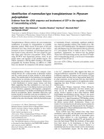
As can be seen from Fig. 2.1, within volume of less than 0.001 mm
3
there are
materials from all basic material groups; polymers (epoxy and polyimide), insu-
lators (SiO
2
and SiN), semiconductors (Si) and metals (Al, Cu, Ni, Sn and Ti) that
all behave differently under varying temperature or stress states. Therefore,
understanding on materials’ compatibility is fundamentally important and provides
the basis for comprehending the ever increasing electrical, thermal, thermo-
mechanical and environmental challenges that must be faced.
T. Laurila et al., Interfacial Compatibility in Microelectronics, Microsystems,
DOI: 10.1007/978-1-4471-2470-2_2, Ó Springer-Verlag London 2012
7
2.1.1 IC Level
Practically all microelectronic devices are based on ‘‘components’’ that are fab-
ricated by employing metal-semiconductor contacts that are integrated with
metallic connectors insulated by ceramic or polymer layers as shown in Fig. 2.2.
Semiconductor devices are based on a vast variety of thin conducting and
insulating layers in contact with each other as well as to semiconducting materials
[3]. Therefore, the interfacial compatibility between dissimilar materials is espe-
cially important on the IC-level. Typically, the main manufacturing and reliability
challenges are related to the polycrystalline conducting thin films, which provide
the electrical contacts between the devices and to the outside world via the
packaging. It is to be noted that the physical and chemical properties of thin films
Fig. 2.1 SEM micrograph and EDS element maps from MEMS accelerometer with integrated ASIC
8 2 Materials and Interfaces in Microsystems
can differ significantly from those of bulk materials. This, on the one hand, pro-
vides a huge amount of possibilities to tailor the material properties, but, on the
other hand, makes the fundamental understanding of materials scientific aspects
even more important, in order to avoid unwanted events. The key issue in com-
prehending the use of thin film structures is through understanding on diffusion
and reaction mechanisms as well as the electrochemical and electromigration
properties of these materials. The huge range of different factors affecting the
failure mechanisms on the IC and packaging level is illustrated in Fig. 2.3 by the
fish-bone diagram.
The above described aspects are mainly related to ‘‘traditional’’ ICs and the
relative importance of these aspects can be quite different when one considers for
instance high power or RF-components as well as LED or MEMS systems. For
Fig. 2.2 Simplified schematic representation of typical frontside material solutions from an
electronic component. (N.B. Layers are not in scale.)
Fig. 2.3 Failure mechanisms in IC and packaging levels
2.1 Levels of Interconnections, Typical Stress Factors and Related Failure Mechanisms 9
example, the major challenges in RF-circuits and modules, in addition to
increasing power consumption and difficulties in thermal management, are related
to low noise and high linearity issues. Therefore different approaches must be
taken for both manufacturing methods and materials selection points of view.
On the other hand, the performance and reliability of LED components are greatly
dependent on thermal management since high operating temperatures at the LED
junction adversely affect performance, resulting both decreased output and life-
time. It is to be emphasised that the majority of LED failure mechanisms are
temperature-dependent. When designing lighting systems using high-power LEDs,
the most important guideline is to minimise the amount of heat that needs to be
removed and enhance the thermal conductivity between the heat sink and the LED.
Since the LED components are typically very reliable, it has been shown that many
lighting applications the packaging or, especially, board-level interconnection
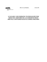
reliability defines the lifetime of the product. Figure 2.4 shows a cross section
from a high-power led-module after 500 cycles of thermal cycling, where the
thermal adhesive between the alumina board and aluminium heat sink has failed.
In addition, it is important to separate the LED drive circuitry from the LED board
so that the heat generated by the driver will not contribute to the LED junction
temperature.
2.1.2 Package Level
As was already mentioned above, the integration of microsystems is continuously
blurring the distinction between the interconnection levels. However, since on the
packaging level the volume drivers have continuously shifted towards consumer
electronics, many material and manufacturing solutions, like ceramic packaging,
Fig. 2.4 Heat-sink attachment failure in high-power LED product after thermal cycling 0
,100°C, 2 h cycle time and 500 cycles (N.B. The LED component is not seen in this section)
10 2 Materials and Interfaces in Microsystems
must be ruled out due to cost factors. Therefore, in this ‘‘cost-performance’’
category the methods used and developed are based on the low-cost polymer and
solder materials and technologies.
Die attach (also known as die mount or die bond) is the process where the
silicon chips are mounted on the substrate. The most commonly used methods are
adhesive or glass bonding and soldering or eutectic die attach. In addition to
mechanical support, the die attach materials also provide thermal and/or electrical
conductivity between the die and the package thus affecting the performance of the
device during field operation. When solder materials are used in the die attach,
backside metallisation of the semiconductor device is required. The backside
metallisation is typically a multilayer structure composed of an adhesion layer, a
barrier/wetting layer and an oxidation protection layer (See Fig. 2.5).
The requirements of a die attach material are application-dependent, but typi-
cally include that (i) mechanical strength must be maintained up to 150°C, (ii) the
attachment process temperature must not affect the die function and (iii) the
attachment should withstand board-level assembly processes (temperatures up to
260°C for a few minutes), the absorption of continuous and cyclic mechanical and
thermomechanical stresses, etc. The most common stress-related failures during
product life are die/adhesive cracks, passivation cracks, pad delamination and
corrosion [4]. Figure 2.6 shows an example of a cracked Si-chip due to lack of
mechanical support of the die attach film during wire bonding in a stacked die
application.
Wirebonding has been the most commonly used method for connecting ICs to
packages or other substrates already now for many decades. The most important
advantages are related to the flexibility of the manufacturing process, long expe-
rience and reliability. Wirebonding can also be considered as low-cost from an
equipment and materials used point of view. There are three methods used:
Thermocompression (T/C), Thermosonic (T/S) and Ultrasonic (U/S) (see
Table 2.1). Depending on the method, the shape of the bond can be either ‘‘ball-
wedge’’ (T/C- or T/S-methods) or ‘‘wedge–wedge’’ (U/S-method). Aluminium
(Si or Ge alloying) wires are typically used with the U/S-method. T/C- and
T/S- methods typically use Au-wires, but Pd, Cu and Ag are also possible.
The challenges in wirebonding are frequently related either to bonding process
parameter control (temperature, pressure, etc.) or to reliability problems caused by
high operational temperatures or aggressive environments. Figure 2.7 shows
optical micrographs from a typical process-related problem, where the Al pad has
been consumed locally by the IMC-reaction with Au-ball due to excessive bonding
temperature.
Fig. 2.5 Schematic
presentation of typical die
attach structure and
commonly used materials
2.1 Levels of Interconnections, Typical Stress Factors and Related Failure Mechanisms 11
Two typical operational stress-related reliability problems are shown in
Figs. 2.8 and 2.9. Local corrosion of an Al pad in a Cl
-
containing environment
can be clearly detected from Fig. 2.8. The EDS element maps show higher
chlorine and oxygen content at the surface pits. Figure 2.9 shows the well-known
‘‘purple plague’’ problem, which is the formation of an excessive amount of AuAl
2
intermetallic at the interface [5]. The growth of AlAu intermetallics is often
accompanied by the formation of so-called Kirkendall voids, which are caused by
Fig. 2.6 Cracked Si-chip due to lack of mechanical support from die attach film
Table 2.1 Three wirebonding methods and their typical properties
Thermocompression (T/C) Thermosonic (T/S) Ultrasonic (U/S)
Definition Contact between wire and
contact pads is based on
plastic deformation and
interfaces
Ultrasound is used
to assist the
disruption of the
oxide layers
Ultrasound is used together
with pressure but no
extern al heating
Temperature 300–400°C 150–200°C Room temperature Bond
interface *7 70–80°C
Pressure l00 g/contact area
Time 0.1 s 5 ms \ t \ 25 ms t\ 25 ms
Bond type ‘‘ball-wedge’’ ‘‘ball-wedge’’ ‘‘wedge–wedge’’
Factors affecting reliability:
Surf ace roughness and
voids, oxidation.
adsorbed impurities,
moisture
Used especially
when wire
bonding thick-
film hybrid
substrates
Problems in ‘‘wedge–wedge’’
is that both contacts have
to be aligned in the same
direction
Wire Usually Au Au. also Cu and pd Al
12 2 Materials and Interfaces in Microsystems
the differences between the intrinsic diffusion fluxes of Al and Au, i.e. Au moves
faster than Al and thus the vacancies accumulate on the Au side.
Tape Automated Bonding (TAB) technology was developed as a low-cost
method during the 1960s for small sale integration (SSI) circuits to replace
wirebonding. During the 1980s, the use of surface mount technology made it more
popular also in high I/O components (see Fig. 2.10). The TAB process uses
typically bumped chips, which are first bonded to metallised tape fingers (ILB,
Inner Lead Bonding). After ILB the chips are tested and/or encapsulated before
singulation and outer lead bonding to a substrate or card.
Fig. 2.7 Au ball | Al pad interfacial reaction during the bonding process
Fig. 2.8 SEM micrograph from local corrosion at the Al-bond pad together with EDS element
maps (violet_chlorine, yellow_aluminum, and red_oxygen)
2.1 Levels of Interconnections, Typical Stress Factors and Related Failure Mechanisms 13
Flip-chip is defined as a bare chip mounted on the substrate upside down, the
active side towards the substrate. Flip-chip technology is the so-called Area Array
method, which means that the whole IC area can be used for interconnections.
Therefore flip-chip provides higher interconnection densities than both wire
bonding and TAB. The I/O contact pads are located under the chip, and connec-
tions to the substrate can be made with various interconnection materials and
methods (see Fig. 2.11), such as solder bumps, conductive adhesives or Stud
Bump Bonding (SBB). The substrate can either be a component (like CSP or
BGA) interposer or a mere PWB (Flip-Chip On Board, FCOB), ceramic (FCOC),
glass (FCOG) or flex (FCOF) substrate.
From an electrical performance point of view flip-chip is also a superior direct
chip attachment method. Due to the advantages of the technology it is commonly
used in microprocessor components. However, as a result of the small height of the
solder interconnections, which are the most commonly used, the large difference in
the coefficients of thermal expansion (CTE) between the Si-chip and the organic
substrate cause reliability problems. Large strains are already formed during the
Fig. 2.9 Left ‘‘purple plague’’ and right AuAl IMC layers [5]
Fig. 2.10 TAB used in a component package
14 2 Materials and Interfaces in Microsystems