IIW RECOMMENDATIONS ON METHODS FOR IMPROVING THE FATIGUE STRENGTH OF WELDED JOINTS pot
Bạn đang xem bản rút gọn của tài liệu. Xem và tải ngay bản đầy đủ của tài liệu tại đây (3.85 MB, 46 trang )
© International Institute of Welding, 2013. Published by Woodhead Publishing Limited
IIW RECOMMENDATIONS
ON METHODS FOR IMPROVING
THE FATIGUE STRENGTH OF
WELDED JOINTS
IIW-2142-10
P. J. Haagensen and S. J. Maddox
Oxford Cambridge Philadelphia New Delhi
© International Institute of Welding, 2013. Published by Woodhead Publishing Limited
Published by Woodhead Publishing Limited,
80 High Street, Sawston, Cambridge CB22 3HJ, UK
www.woodheadpublishing.com
www.woodheadpublishingonline.com
Woodhead Publishing, 1518 Walnut Street, Suite 1100, Philadelphia, PA 19102-3406, USA
Woodhead Publishing India Private Limited, G-2, Vardaan House, 7/28 Ansari Road, Daryaganj, New Delhi – 110002, India
www.woodheadpublishingindia.com
First published 2013, Woodhead Publishing Limited
© International Institute of Welding, 2013
The authors have asserted their moral rights.
This book contains information obtained from authentic and highly regarded sources. Reprinted material is quoted with
permission, and sources are indicated. Reasonable efforts have been made to publish reliable data and information, but the
authors and the publisher cannot assume responsibility for the validity of all materials. Neither the authors nor the publisher,
nor anyone else associated with this publication, shall be liable for any loss, damage or liability directly or indirectly caused or
alleged to be caused by this book.
Neither this book nor any part may be reproduced or transmitted in any form or by any means, electronic or mechanical,
including photocopying, microfilming and recording, or by any information storage or retrieval system, without permission in
writing from Woodhead Publishing Limited.
The consent of Woodhead Publishing Limited does not extend to copying for general distribution, for promotion, for creating
new works, or for resale. Specific permission must be obtained in writing from Woodhead Publishing Limited for such copying.
Trademark notice: Product or corporate names may be trademarks or registered trademarks, and are used only for
identification and explanation, without intent to infringe.
British Library Cataloguing in Publication Data
A catalogue record for this book is available from the British Library.
ISBN 978-1-78242-064-4 (print)
ISBN 978-1-78242-065-1 (online)
The publisher’s policy is to use permanent paper from mills that operate a sustainable forestry policy, and which has been
manufactured from pulp which is processed using acid-free and elemental chlorine-free practices. Furthermore, the publisher
ensures that the text paper and cover board used have met acceptable environmental accreditation standards.
Typeset by Toppan Best-set Premedia Limited, Hong Kong
Printed and bound in the UK by the MPG Books Group
© International Institute of Welding, 2013. Published by Woodhead Publishing Limited
CONTENTS
1. INTRODUCTION 1
2. SCOPE 2
2.1 Methods 2
2.2 Materials 2
2.3 Environment and Loading 3
2.4 Types of Welded Joints 3
3. BURR GRINDING 4
3.1 Introduction 4
3.2 Equipment 4
3.3 Safety Aspects 5
3.4 Weld Preparation 5
3.5 Procedure 5
3.6 Corrosion Protection 8
3.7 Operator and Inspector Training 9
3.8 Inspection, Quality Control and Documentation 9
3.9 Fatigue Strength of Joints Improved by
Burr Grinding 10
3.10 Thickness Effect for Joints Improved by
Burr Grinding 12
4. TUNGSTEN INERT GAS (TIG)
DRESSING 12
4.1 Introduction 12
4.2 Equipment 12
4.3 Weld Preparation 13
4.4 Dressing Conditions and Procedure 14
4.5 Operator and Inspector Training 18
4.6 Remedial Dressing 18
4.7 Corrosion Protection 18
4.8 Inspection, Quality Control and Documentation 18
4.9 Fatigue Strength of Joints Improved by
TIG Dressing 19
4.10 Thickness Effect for Joints Improved by
TIG Dressing 21
5. HAMMER PEENING 21
5.1 Introduction 21
5.2 Equipment 21
5.3 Operator and Inspector Training 22
5.4 Weld Preparation 22
5.5 Safety Aspects 23
5.6 Procedure 23
5.7 Inspection, Quality Control and Documentation 25
5.8 Fatigue Strength of Joints Improved by
Hammer Peening 26
5.9 Stress Ratio Effects for Joints Improved by
Hammer Peening 28
5.10 Thickness Effect for Joints Improved by
Hammer Peening 29
6. NEEDLE PEENING 29
6.1 Introduction 29
6.2 Equipment 29
6.3 Operator Training 30
6.4 Weld Preparation 30
6.5 Safety Aspects 30
6.6 Procedure 31
6.7 Inspection, Quality Control and Documentation 31
6.8 Fatigue Strength of Joints Improved by
Needle Peening 31
6.9 Stress Ratio Effects for Joints Improved by
Needle Peening 34
6.10 Thickness Effect for Joints Improved by
Needle Peening 34
7. RECOMMENDATIONS
RELATED TO STRUCTURAL
HOT-SPOT STRESS 34
8. REFERENCES 35
APPENDICES 36
Appendix 1: Participants in IIW Inter-laboratory
Test Programme 36
Appendix 2: Bibliography of
Publications Consulted 37
Appendix 3: Production Data Sheets 39
INTRODUCTION 1
© International Institute of Welding, 2013. Published by Woodhead Publishing Limited
1. INTRODUCTION
Weld toe improvement methods have been widely investigated and have, in most cases, been found to give substantial
increases in fatigue strength. However, there are large variations in the actual improvements achieved, and the results
obtained by various methods are not always ranked in a consistent manner. One explanation for the observed varia-
tions is the lack of standardization of the optimum method of application, but variations in the material, type of loading
and type of weld detail may also have influenced the results. The effectiveness of the treatment also depends heavily
on the skill of the operator. In order to improve the reproducibility of the methods, and to produce guidance for the
degree of improvement that could be expected when using the methods in actual practice, an inter-laboratory round-
robin test programme was undertaken by IIW in 1995 (Haagensen, 1995). The participating organizations are listed
in Appendix 1. The programme, involving 13 testing laboratories in 10 countries, addressed the 3 commonly used
improvement methods: burr grinding, TIG dressing and hammer peening. It has contributed to a better understanding
of the reasons for the large scatter that is sometimes observed in fatigue tests of improved welds, and has provided
a basis for a higher confidence in the use of the methods.
The recommendations in this document are derived mainly from earlier IIW publications (Maddox, 1993; Haagensen,
1993; Millington, 1973; and Kado
et al
., 1975), but many publications were consulted, as listed in Appendix 2. They
supplement the IIW Recommendations for Fatigue Design of Welded Joints and Components (Hobbacher, 2009),
which present S-N curves expressed in terms of applied nominal or hot-spot stress range. These are of the form
Δσ
m
N
= constant, where Δσ is the stress range,
N
is the fatigue life and
m
is the inverse slope of the log Δσ vs
log
N
curve. The benefits from the use of the improvement techniques are related to those design S-N curves. In
addition to specifications for the practical use of the methods, guidance on inspection and quality control is also
given. Successful implementation of these methods depends on adequate training of operators as well as inspectors.
It is anticipated that publication of the present Recommendations will encourage the production of appropriate train-
ing aids and guidance for educating, training and certifying operators and inspectors.
The improvement techniques described in these Recommendations are intended for use under the following
circumstances:
❚
increasing the fatigue strength of new structures;
❚
repair or upgrading of existing structures.
It should be noted that the use of the higher S-N curves for improved welds given in this document depends criti-
cally on adherence to the quality requirements outlined under each improvement technique. Depending on the cir-
cumstances, approval from, for example, the purchaser or a certifying authority may be required before an improvement
technique is used and an increase in fatigue strength is claimed.
2 FATIGUE STRENGTH IMPROVEMENT METHODS
© International Institute of Welding, 2013. Published by Woodhead Publishing Limited
2. SCOPE
2.1 Methods
The weld toe is a primary source of fatigue cracking because of the severity of the stress concentration it produces.
Apart from a relatively sharp transition from the plate surface to the weld, dependent on the weld profile, the stress
concentration effect is enhanced by the presence of minute crack-like flaws, extending to depths (below any under-
cut) of a few tenths of a millimetre. Fatigue cracks readily initiate at these flaws.
The weld toe improvement methods described in these Recommendations rely on two main principles:
(i)
Reduction of the severity of the weld toe stress concentration
– two methods are given: grinding and re-
melting by TIG dressing. The primary aim is to remove or reduce the size of the weld toe flaws and thus
extend the crack initiation part of the fatigue life. A secondary aim is to reduce the local stress concentra-
tion due to the weld profile by achieving a smooth blend at the transition between the plate and the weld
face.
(ii)
Introduction of beneficial compressive residual stress
– this has the effect of ‘clamping’ the weld toe
in compression, with the result that an applied tensile stress must first overcome the residual stress
before it becomes damaging. Thus, the applied stress range is less damaging. Two methods are given,
hammer and needle peening. In each case, compressive residual stresses are induced by mechanical
plastic deformation of the weld toe region. Residual stresses then arise as a result of the constraint imposed
by the surrounding elastic material. Similar effects may be achieved with other techniques, such as
shot peening and high-frequency (e.g. ultrasonic) peening (e.g. Kudryavtsev
et al
., 2007; Weich, 2009a
and 2009b; and Roy
et al
., 2003), and they will be addressed in a future up-date of these
Recommendations.
An important practical limitation on the use of improvement techniques that rely on the presence of compressive
residual stresses is that their fatigue lives are strongly dependent on the applied mean stress of the subsequent
fatigue loading. In particular, their beneficial effect decreases as the maximum applied stress approaches tensile
yield, disappearing altogether at maximum stresses above yield. Thus, in general the techniques are not suitable
for structures operating at applied stress ratios (
R
) of more than 0.4 or maximum applied tensile stresses
above around 80% yield. Similarly, their benefit may be reduced under variable amplitude loading as a result of
relaxation of the compressive residual stress by the occasional application of high stresses, in tension or
compression.
2.2 Materials
The Recommendations apply to any arc welded steel or aluminium structure that is subjected to fatigue loading.
Due to lack of experimental data for extra high strength steels, the fatigue strength (or S-N) curves apply only to
structural steel and stainless steel grades up to a maximum specified yield strength of 900 MPa. However, it is
reasonable to expect that, in principle, the methods will also improve the fatigue performance of welded higher
strength steels. In the absence of relevant published data, it is recommended that such benefit should be quantified
by special testing. The present Recommendations are also applicable to aluminium alloys commonly used in welded
structures, primarily the 5000 and 6000 series alloys.
SCOPE 3
© International Institute of Welding, 2013. Published by Woodhead Publishing Limited
2.3 Environment and Loading
The application of improvement techniques is limited to structures operating at temperatures below the creep range.
Although some of the improvement methods will increase the fatigue lives of structures operating under freely cor-
roding conditions, no guidance is given on the improvement that can be expected.
The Recommendations for burr grinding and TIG dressing only apply to conditions where the nominal stress range
Δσ < 2 ×
YS
,
YS
being the specified minimum yield strength of the material.
For peening techniques, special restrictions are imposed regarding applied peak stresses and stress ratios, see
Sections 5 and 6. Consistent with the IIW Recommendations for Fatigue Design of Welded Joints (Hobbacher,
2009), the present Recommendations do not apply to low-cycle fatigue conditions. However, there is evidence that
the weld toe dressing methods are still effective under strain cycling (Dickerson and Branco, 1997).
2.4 Types of Welded Joints
The current Recommendations apply to the improvement of welded planar joints or welded hollow section connec-
tions with plate thickness from 6 to 50 mm for steel, 4 to 20 mm for aluminium, or as specified for each improve-
ment method.
The improvement methods covered in this document are applied to the weld toe. Thus, they are intended to increase
the fatigue life of the weld treated from the viewpoint of potential fatigue failure from the weld toe (some examples
of relevant weld details are show in Fig. 2.1). Therefore, the possibility of a failure starting at some other location
must always be considered. For instance, if the failure origin is merely shifted from the weld toe to the root, there
may be no significant improvement in fatigue life. It is emphasized that fatigue cracking from the root is governed
by different design curves so toe treatment cannot be expected to provide any improvement in the general case.
Improvement of details with incomplete penetration should be verified by fatigue testing or by analysis (Hobbacher,
2009). Examples of details in which root cracking might occur are shown in Fig. 2.2, but even nominally non-load-
carrying welds may fail from the root when the toe has been improved. Consequently, when weld improvement is
planned, full penetration welds or welds with extra large throats should be used where possible, particularly for welds
at the ends of cover plates or longitudinal stiffeners.
(a) (b)
(c) (d)
Fig. 2.1
Examples of joints suitable for improvement
4 FATIGUE STRENGTH IMPROVEMENT METHODS
© International Institute of Welding, 2013. Published by Woodhead Publishing Limited
3. BURR GRINDING
3.1 Introduction
The primary aim of grinding is to remove or reduce the size of the weld toe flaws from which fatigue cracks propa-
gate. At the same time, it aims to reduce the local stress concentration effect of the weld profile by smoothly blending
the transition between the plate and the weld face.
3.2 Equipment
A high-speed pneumatic, hydraulic or electric grinder with rotational speed from 15 000 to 40 000 rpm is required.
A pressure from 5 to 7 bar for air-driven grinders is recommended. The tool bit is normally a tungsten carbide burr
(or rotating file) with a hemispherical end (Fig. 3.1).
(a) (b)
(c)
(d)
Fig. 2.2
Examples of details for which the improvement in fatigue
strength is likely to be limited by the occurrence of root
cracking. To ensure that a significant increase in fatigue
strength is obtained, full penetration welds should be used
in cases (a), (c) and (d), while an extra large weld throat
should be used in case (b)
Fig. 3.1
Pneumatic grinder and burrs
BURR GRINDING 5
© International Institute of Welding, 2013. Published by Woodhead Publishing Limited
To avoid a notch effect due to small radius grooves, the burr diameter should be scaled to the plate thickness (
t
) at
the weld toe being ground (see Section 3.5). The diameter should be in the 10 to 25 mm range for application to
welded joints with plate thickness from 10 to 50 mm, and the resulting root radius of the groove should be no less
than 0.25
t
.
3.3 Safety Aspects
The high-speed grinding tool removes material at a high rate and is therefore capable of inflicting serious injuries
to the operator or bystanders. The cutting operation itself produces hot, sharp cuttings and some noise. Therefore,
appropriate protective clothing together with leather gloves, safety glasses and ear protection are strongly
recommended.
3.4 Weld Preparation
The weld should be de-slagged and cleaned by wire brushing before burr grinding.
3.5 Procedure
The quality of grinding depends on the skill of the operator, and each operator should experiment to find a technique
that gives the desired result. Therefore, only general advice is given below.
Start
toe grind
Direction
of travel
(a) (b)
45–60°
30–45°
Stiffener plate Existing weld
Approximately 4 x t
Stress
Grind toe
continuously
along both
sides and around
end of stiffener plate
Fig. 3.2
The weld toe burr grinding technique
6 FATIGUE STRENGTH IMPROVEMENT METHODS
© International Institute of Welding, 2013. Published by Woodhead Publishing Limited
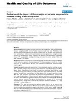
The burr grinding procedure is illustrated in Fig. 3.2. The burr is centred over the weld toe. The axis of the tool should
be 45–60° to the main plate, and approximately 45° to the direction of travel. The grinder can be either pushed or
pulled along the weld. Usually, the former is more successful at establishing a straight groove of even depth. Grind-
ing has to be extended to areas well outside the highest stress region at the ends of attachments, as indicated for
plate thickness
t
in Fig. 3.2(b).
In general, grinding must extend to a depth of at least 0.5 mm below any visible undercut, see Fig. 3.3. For plates
up to 30 mm thick the maximum allowable depth is 7% of the plate thickness, with a limit of 2 mm for thicker
members. However, it is clearly preferable to minimize the depth of groove produced and, in general, a maximum of
1 mm should be sufficient.
3.5.1 Large-scale Joints
In large-scale planar welded joints with plate thickness in the order of 40 mm and more, the high notch stresses in
the toe region extend up on the weld face, and inter-bead toes may also become crack initiation sites. This applies
in particular to welds with low weld face angles. Such inter-bead toes should also be ground. As a guide, it should
be sufficient to extend the treatment up the weld face by a distance (
w
) of at least half the leg length
h
, as illustrated
in Fig. 3.3, but more extensive grinding may be prudent in critical cases. In this respect, a particular case where this
situation arises is for welds in tubular joints, particularly those with large beta ratios (β = brace diameter/chord
diameter), where the maximum stress is likely to be located on the weld face. Thus, as well as both weld toes, it is
advisable to grind the whole weld face. The situation is illustrated in Fig. 3.4.
The weld toe geometry to be achieved by burr grinding is illustrated in Fig. 3.5. Note that an adequate throat thick-
ness must be maintained for static strength and to limit the possibility of premature fatigue failure through the weld
throat. As mentioned earlier, it is important that the burr radius
r
is scaled to the plate thickness and to the grinding
depth
d
, otherwise the stress concentration factor will increase with increasing thickness. Unless alternative dimen-
sions can be justified, those in Fig. 3.5 are recommended.
w = h/2
h
t
Depth of grinding
Depth of grinding should
be 0.5 mm below bottom
of any visible undercut
Maximum 2 mm or 7%
of plate thickness
Fig. 3.3
The burr grinding technique, showing depth and width of groove
in the stressed plate
BURR GRINDING 7
© International Institute of Welding, 2013. Published by Woodhead Publishing Limited
Brace wall
Peak stress
on weld face
Stress at weld toe
Chord wall
Weld face
Fig. 3.4
Stress distribution in a tubular joint (schematic), requiring
grinding of the entire weld face and the weld toes in the
brace and the chord
d = min. 0.5 mm below undercut
r/t > 0.25
Ground
profile
Depth gauge
Depth measurementPlate
Weld
Original
profile
Grinding
depth
Original
toe
(Not to scale)
Root
Minimum throat to
be maintained
r/d > 4
r
d
t
Fig. 3.5
Details of burr ground weld toe geometry
3.5.2 Two-stage Grinding
In the case of a steep weld angle fillet or T butt welds in thick plates, for which large diameter burrs are required,
it is often found that the burr has a tendency to ‘climb’ up the weld face, making it difficult to position it on the weld
toe line. In such circumstances, it is recommended that grinding should be carried out in two stages. First, a small
spherical tool, e.g. 6 mm diameter, is used to establish a groove of the correct depth and position, see Fig. 3.6. The
grinding operation is then completed with the larger diameter burr. In this way, it is easier to obtain the required
quality of grinding in less time than when using the large diameter tool alone.
8 FATIGUE STRENGTH IMPROVEMENT METHODS
© International Institute of Welding, 2013. Published by Woodhead Publishing Limited
The grinding rate depends on the weld geometry and the material, but will be typically 50 to 100 mm per minute.
The finished ground surface should be as smooth as possible, with no visible evidence of the original weld toe and
any grinding marks at right angles to the weld toe line. Examples of the appearance of correctly and incorrectly
ground welds are shown in Fig. 3.7 (a) and (b), respectively.
3.6 Corrosion Protection
Corrosion pitting of the ground metal surface virtually eliminates the benefit of burr grinding. Therefore, the ground
surface must be adequately protected. The protection may be of a temporary nature, as would be the case for a
part of an offshore structure that would eventually be submerged and protected by a cathodic protection system. In
other cases, permanent protection must be provided, e.g. paint.
Small diameter
cylindrical burr
Large diameter
cylindrical burr
d = required final depth
Fig. 3.6
Two-stage grinding of large welds with steep weld angles
(a) (b)
Fig. 3.7
Appearance of correctly and incorrectly burr ground fillet weld toes.
(a) Correctly ground weld toe, (b) incorrectly ground weld toe
BURR GRINDING 9
© International Institute of Welding, 2013. Published by Woodhead Publishing Limited
3.7 Operator and Inspector Training
Some skill is required to perform burr grinding according to this specification, and a training programme should be
implemented for inexperienced operators. This should include a demonstration of the appearance of an adequately
ground weld as well as a demonstration of unacceptable welds, and an explanation of the factors that influence the
result. Actual grinding of at least 2 metres of weld, combined with periodic inspection and evaluation, is
recommended.
3.8 Inspection, Quality Control
and Documentation
The inspection procedure must include a check on the weld toe radius, the depth of grinding and confirmation
that the weld toe has been removed completely. A depth gauge similar to the one used for measuring weld toe
undercut (see Fig. 3.8(a)) may be used, although the accuracy is low. Alternatively, a ‘go–no go’ type of gauge, such
as shown in Fig. 3.8(b), may be more suitable. Visual examination under a bright light should be made to ensure
that all traces of the original weld toe have disappeared. The ground surface of the groove should be inspected to
make sure there are no deep scratches along the weld toe. A low-power (approximately x5) magnifying glass is
suitable.
A cast of the weld made using a silicone rubber of the type used by dentists is useful for documentation and for
measuring the local geometry at the weld toe.
Data pertaining to the procedure should be recorded for the purpose of quality control and quality assurance. The
data are also useful for correlating fatigue performance with burr grinding conditions when fatigue testing is per-
formed. Examples of suitable data sheets, similar to those used for welding procedure specification, are reproduced
in Appendix 3.
(a)
(b)
Fig. 3.8
Gauges for checking depth of groove
10 FATIGUE STRENGTH IMPROVEMENT METHODS
© International Institute of Welding, 2013. Published by Woodhead Publishing Limited
3.9 Fatigue Strength of Joints Improved by
Burr Grinding
The benefit of weld toe burr grinding for steel can be claimed only for details in FAT 90 Class or lower in the IIW
notation for S-N curves. This limitation is due to the fact that the higher classes include non-welded details, details
whose lives are not governed by weld toe failure or welds that have already been improved, e.g. by grinding a butt
weld flush with the surface.
For IIW FAT 90 or lower class details, the benefit of burr grinding corresponds to an increase in allowable stress
range by a factor of 1.3, corresponding to a factor of 2.2 on life (for
m
= 3, the appropriate value for FAT 90 and
lower). However, the maximum class that can be claimed is the closest category below the FAT value obtained when
the as-welded FAT value is multiplied by 1.3. For ease of computation, this corresponds to a two fatigue class
increase. For example, when a weld detail that, in the as-welded condition, would be classified as FAT 63 is burr
ground, the new FAT value is FAT 80. In Fig. 3.9, this S-N curve is denoted as 80 (63). The highest S-N curve that
can be claimed following improvement is FAT 112, as shown in Fig. 3.9. The slopes of the S-N curves follow the
IIW Recommendations for Fatigue Design (Hobbacher, 2009). For variable amplitude loading, the slope is changed
from
m
= 3 to
m
= 5 at
N
= 10
7
cycles for FAT 112 details and lower. For constant amplitude loading there is either
a change to a horizontal line (fatigue limit) at 10
7
cycles or, under special conditions, the slope parameter
m
is
changed to 22 at 10
7
cycles, see Section 3.2 of Hobbacher (2009).
Steel – burr grinding
Note: FAT numbers in brackets refer to
detail categories in the as-welded condition,
i.e. before treatment
FAT
160 (parent material)
112 (90)
100 (80)
90 (71)
80 (63)
71 (56)
63 (50)
56 (45)
50 (40)
45 (36)
Number of cycles, N
1E+4
10
100
Stress range
∆σ
(MPa)
1000
1E+5 1E+6 1E+7 1E+8
Fig. 3.9
Design S-N curves for details improved by weld toe burr grinding in steel
structures, variable amplitude loading
BURR GRINDING 11
© International Institute of Welding, 2013. Published by Woodhead Publishing Limited
As shown in Fig. 3.9, all S-N curves in the low endurance region are limited by the parent material curve, i.e. the
FAT 160 curve with a slope parameter of
m
= 5 (Hobbacher, 2009).
For welds improved by grinding in aluminium alloys, the benefit of burr grinding corresponds to an increase in allow-
able stress range by a factor of 1.3, corresponding to a factor of 2.2 on life (for
m
= 3). However, the maximum
class that can be claimed is the closest category below the FAT value obtained when the as-welded FAT value is
multiplied by 1.3. For ease of computation, this corresponds to a two fatigue class increase. For example, when an
aluminium weld detail that, in the as-welded condition, would be classified as FAT 22 is burr ground, the new FAT
value is FAT 28. In Fig. 3.10, this S-N curve is denoted as 28 (22). The highest detail class for which an improve-
ment can be claimed is FAT 36. The design class FAT 12 curve does not appear in Fig. 3.10 because it represents
fatigue failure from the weld root, which is not influenced by burr grinding. The highest S-N curve that can be claimed
following improvement is FAT 45, as shown in Fig. 3.10. The slopes of the S-N curves follow the IIW Recommenda-
tions for Fatigue Design. For variable amplitude loading, the slope is changed from
m
= 3 to
m
= 5 at
N
= 10
7
cycles
for FAT 50 details and lower. For constant amplitude loading,
m
is changed to 22 at
N
= 10
7
cycles, see Section
3.2 of Hobbacher (2009).
As for steel, and as shown in Fig. 3.10, all S-N curves in the low endurance region are limited by the parent material
design curve, i.e. the FAT 71 curve with a slope parameter of
m
= 5.
Aluminium – burr grinding
Number of cycles, N
100
1000
10
1
Stress range
∆σ
(MPa)
1E+4 1E+5 1E+6 1E+7 1E+8
FAT
71 (parent material)
45 (36)
40 (36)
36 (28)
32 (28)
28 (22)
25 (22)
20 (16)
18 (14)
22 (18)
Note: FAT numbers in brackets refer
to detail categories in the as-welded
condition, i.e. before treatment
Fig. 3.10
Design S-N curves for details improved by weld toe burr grinding in
aluminium structures, variable amplitude loading
12 FATIGUE STRENGTH IMPROVEMENT METHODS
© International Institute of Welding, 2013. Published by Woodhead Publishing Limited
3.10 Thickness Effect for Joints Improved
by Burr Grinding
Weld toe grinding reduces the stress concentration factor, and in accordance with Section 3.5.2 of Hobbacher
(2009), the thickness correction factor
f
(
t
) for toe ground joints is:
f t
t
eff
( )
.
=
25
0 20
[3.1]
where
t
eff
=
L
/2 for
L
/
t
< 2 and
t
eff
=
t
for
L
/
t
≥ 2;
L
is the sum of the thickness or length of the attachment and
the weld leg lengths as shown in Fig. 3.11 (Hobbacher 2009).
L L
t
Fig. 3.11
Definition of L, used to determine the
thickness correction factor
4. TUNGSTEN INERT GAS (TIG)
DRESSING
4.1 Introduction
The objective of TIG dressing is to remove the weld toe flaws by re-melting the material at the weld toe. It also aims
to reduce the local stress concentration effect of the local weld toe profile by providing a smooth transition between
the plate and the weld face.
The present Recommendations are applicable only to connections with main plate thicknesses of at least 4 mm for
aluminium and 6 mm for steel.
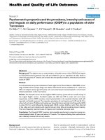
4.2 Equipment
A standard TIG welding machine is used, normally with argon as shielding gas. The addition of helium is beneficial
since this gives a larger pool of melted metal due to a higher heat input. Typical conditions and range of dressing
parameters used in reported tests are shown in Table 4.1, while Fig. 4.1 shows manual TIG dressing of a weld toe.
TUNGSTEN INERT GAS (TIG) DRESSING 13
© International Institute of Welding, 2013. Published by Woodhead Publishing Limited
4.3 Weld Preparation
TIG dressing is sensitive to most types of common plate and weld surface contaminants, such as mill scale, rust, oil
and paint. The weld and adjacent plate should be thoroughly de-slagged and wire brushed. If necessary, light grind-
ing should be used to obtain a clean surface. Insufficient cleaning tends to result in the formation of gas pores that
can have a strongly detrimental effect on fatigue performance. The problem of porosity is particularly important in
TIG dressed aluminium welds.
Table 4.1 Typical TIG dressing conditions for steel
Shielding gas Argon or argon + helium
a
Gas flow rate 7–12 litre/min
Nozzle diameter 10–14 mm
Preheat
50–200°C
Electrode diameter 3 to 4 mm
Voltage (
V
) 12–17 volts
Current (
A
) 160–250 amperes
Dressing speed (
S
) 80–160 mm/min
Heat input (
Q
)
b
1.0–2.5 kJ/mm
a
Dependent on steel type and plate thickness.
b
Heat input is calculated from
Q
V A
S
=
×
60
1000
(kJ/mm).
Fig. 4.1
TIG dressing equipment and
a partially dressed weld
14 FATIGUE STRENGTH IMPROVEMENT METHODS
© International Institute of Welding, 2013. Published by Woodhead Publishing Limited
4.4 Dressing Conditions and Procedure
4.4.1 Tungsten Electrode
The shape of the arc depends on the shape and condition of the electrode tip. If the tip is contaminated, or rounded
by wear (oxidation), the arc becomes concentrated, with the result that the re-melted zone narrows with an unfavour-
able effect on the bead shape. It is also difficult to start the arc and to keep it stable. These problems can be avoided
by re-grinding the tip or replacing the electrode. Acceptable and unacceptable electrode tips are shown in Fig. 4.2
(a) and (b) respectively.
(a)
(b)
Fig. 4.2
Electrodes for TIG torch: (a)
unused tip, (b) contaminated
electrode used on oxidized
plate (after Millington, 1973)
4.4.2 Shielding Gas
If the gas flow rate is low, or strong draughts disturb the gas shield, the arc becomes unstable and defects such as
surface pores are formed, or the electrode and bead oxidize. An adequate gas supply rate depends on many factors,
including gas shroud (cup) size, welding conditions and welding location (presence of draughts). An optimum flow
rate should therefore be determined by trial dressing. For TIG dressing of duplex stainless steels, it is advisable to
add 1% to 2% nitrogen to the shielding gas to avoid unfavourable changes to the austenite–ferrite balance.
TUNGSTEN INERT GAS (TIG) DRESSING 15
© International Institute of Welding, 2013. Published by Woodhead Publishing Limited
4.4.3 Pre-heat (Steel Only)
The heat input during TIG dressing is normally less than that used for welding the joint. Therefore, as a general rule,
the minimum pre-heat temperature used should be equal to that specified in the welding procedure. The exception
to this is welds produced by the flux-cored arc welding (FCAW) process on account of their high hydrogen content.
If TIG dressing is carried out just after welding, a pre-heat of approximately 150°C for a minimum of 20 minutes
must then be chosen to avoid cracking of the weld metal. However, some time after welding is completed, the
hydrogen content is less and the risk of weld metal cracking is reduced, with the result that the pre-heat temperature
can be reduced. In this case, therefore, the pre-heat temperature for TIG dressing of FCAW joints may be chosen
on the basis of the pre-heat temperature that would be used for MMA welding. For steels with a carbon content in
excess of 0.12% weight, the possible formation of hard zones in the heat-affected zone (HAZ) should be considered.
In such cases, a second tempering TIG pass on the weld metal should be considered (Haagensen, 1978).
4.4.4 Dressing Parameters
The objective of TIG dressing is to obtain a smooth transition from the plate to the weld bead. Dressing conditions
may vary with welding position, but, as a general rule, a high heat input should be used since this normally gives a
low hardness in the HAZ as well as allowing higher dressing speeds. However, care is needed since excessive heat
input caused by a combination of high current and a low travel speed usually produces undercut or a poor bead
profile. Suitable dressing conditions for the horizontal–vertical position are shown in Fig. 4.3.
Horizontal–vertical
without filler
Travel speed (mm/min)
0
40 80 120
100
150
200
250
160 200 240 280 320
Welding current (A)
Fig. 4.3
TIG dressing conditions for steel (Millington, 1973)
4.4.5 Position of TIG Torch and Dressing Zone
For an optimum result, the re-melted zone has to be positioned carefully with respect to the original weld toe. Nor-
mally, the best result is obtained when the arc centre is located a small distance
p
away from the weld toe, as
indicated in Fig. 4.4(a). Also shown in Fig. 4.4(a) is a slight sideways tilt of the torch from the perpendicular position
to obtain a favourable bead profile. In addition, the small backward tilt shown in Fig. 4.4(b) may help to maintain an
adequate gas shield.
16 FATIGUE STRENGTH IMPROVEMENT METHODS
© International Institute of Welding, 2013. Published by Woodhead Publishing Limited
If the arc is positioned too close to the weld bead, it may result in the formation of a new toe as shown in Fig. 4.5(b)
and (c). In general, the electrode should be directed more towards the parent plate for steeper weld profiles, whereas
for flatter beads, the electrode should be positioned closer to the weld toe. If bead shapes similar to those shown
in Fig. 4.5(b) and (c) are obtained, remedial treatment should be considered, see Section 4.6. A re-melted weld toe
as shown in Fig. 4.5(a) represents an optimum shape with respect to fatigue. An example of a satisfactorily treated
weld profile is shown in Fig. 4.6. Care is also needed to ensure that the original weld toe is, in fact, re-melted.
Experience indicates that the fatigue life of a region where TIG dressing has missed the toe is the same as that of
the as-welded joint.
60–90°
~10°
Direction of travel
(a) (b)
p = 0–2 mm
Fig. 4.4
Typical position of torch and dressing zone
Optimized profile
Non-optimized
profile
Toe ~ 0.5 mm
0.5 mm ~ toe
1.5 ~ 0.5 mm
(a)
(b)
(c)
Non-optimized
profile
Fig. 4.5
Position of TIG torch tip in relation to weld toe, and resulting
profiles: (a) over plate, 0.5 to 1 mm from toe; (b) over plate,
less than 0.5 mm from toe; (c) over weld, up to 0.5 mm from toe
(Kato et al. 1975)
TUNGSTEN INERT GAS (TIG) DRESSING 17
© International Institute of Welding, 2013. Published by Woodhead Publishing Limited
4.4.6 Arc Stopping and Restarting
Arc stopping and starting may create craters or unfavourable bead profiles. This can be avoided by restarting the
arc about 6 mm behind a stop position, as indicated in Fig. 4.7(a). Alternatively, the arc may be started on the bead
and moved to the toe, Fig. 4.7(b). The stop can also be made on the bead, Fig. 4.7(c). The methods illustrated in
Fig. 4.7(a) to (c) may be combined, as shown in Fig. 4.7(d). Craters may also be avoided by changing the direction
of arc movement, see Fig. 4.7(e). The operator should try various stop/restart techniques and choose one that gives
a favourable bead shape.
(a) (b)
Fig. 4.6
Fillet weld (a) before and (b) after TIG dressing
(x2 magnification)
Direction of
welding
Direction
of welding
(a)
(b) (e)
(d)
(c)
Direction
of welding
Direction of
welding
Change direction
of welding
Restart
Restart
Restart
Stop
Stop
Stop
Stop
Stop
Stop
6 mm
overlap
Fig. 4.7
TIG dressing stop and restart techniques (after Millington, 1973)
18 FATIGUE STRENGTH IMPROVEMENT METHODS
© International Institute of Welding, 2013. Published by Woodhead Publishing Limited
4.5 Operator and Inspector Training
The quality of TIG dressing depends on an optimum combination of dressing parameters and the manual skills
of the operator. The optimum dressing conditions are related to the individual characteristics of the welding equip-
ment. The optimum shape of the dressed profile also depends to some extent on the shape of the initial bead profile.
For this reason it is recommended that a trial programme be set up to familiarize the welder with the technique and
develop optimum dressing conditions. The trials should include dressing with different heat inputs and torch posi-
tions. Arc starting and stopping techniques should also be practised, see Section 4.4.6. After completing the training,
the operator should treat at least 1 metre of similar weld before starting production treatment.
4.6 Remedial Dressing
If the TIG-dressed weld does not satisfy the inspection criterion with respect to weld shape (see Section 4.8), a
new dressing run may be performed. If necessary, a weaving technique may be tried or filler material could be added.
The ease of repeating TIG dressing is one of the advantages of this method.
4.7 Corrosion Protection
The benefit of TIG dressing is reduced if the surface is degraded by corrosion. Therefore, for maximum benefit,
the TIG-dressed surface must be adequately protected against possible corrosion. The protection may be of a tem-
porary nature, as would be the case for a part of an offshore structure that would eventually be submerged and
protected by a cathodic protection system. In other cases, permanent protection must be provided by other means,
e.g. paint.
4.8 Inspection, Quality Control
and Documentation
The dressed weld should have a smooth transition from the plate to the weld face, in accordance with Figs 4.5 and
4.6. The minimum toe radius at this transition region is 3 mm, but larger radii are allowable and may permit easier
inspection. The weld should be checked for complete treatment along the entire length of the part treated. If any
part of the weld toe has been missed by the TIG dressing, it should be treated again.
Data pertaining to the procedure should be recorded for the purpose of quality control and quality assurance. The
data are also useful for correlating fatigue performance with TIG dressing conditions when fatigue testing is per-
formed. An example of a data sheet for TIG dressing, similar to that used for welding procedure specification, is
reproduced in Appendix 3.
TUNGSTEN INERT GAS (TIG) DRESSING 19
© International Institute of Welding, 2013. Published by Woodhead Publishing Limited
4.9 Fatigue Strength of Joints Improved by
TIG Dressing
The benefit of TIG dressing for steel can be claimed only for details in FAT 90 Class or lower in the IIW notation
for S-N curves. This limitation is due to the fact that the higher classes include non-welded details, details whose
lives are not governed by weld toe failure or welds that have already been improved, e.g. by grinding a butt weld
flush with the surface.
For IIW FAT 90 or lower class details, the benefit of TIG dressing corresponds to an increase in allowable stress
range by a factor of 1.3, corresponding to a factor of 2.2 on life (for
m
= 3, the appropriate value for FAT 90 and
lower). However, the maximum class that can be claimed is the closest category below the FAT value obtained when
the as-welded FAT value is multiplied by 1.3. For ease of computation, this corresponds to a two fatigue class
increase. For example, when a weld detail that, in the as-welded condition, would be classified as FAT 63 is improved
by TIG dressing, the new FAT value is FAT 80. In Fig. 4.8, this S-N curve is denoted as 80 (63). The highest S-N
curve that can be claimed following improvement is FAT 112, as shown in Fig. 4.8. The slopes of the S-N curves
follow the IIW Recommendations for Fatigue Design (Hobbacher, 2009). For variable amplitude loading, the slope
is changed from
m
= 3 to
m
= 5 at
N
= 10
7
cycles for FAT 112 details and lower. For constant amplitude loading
there is either a change to a horizontal line (fatigue limit) at
N
= 10
7
cycles or, under special conditions, the slope
parameter
m
is changed to 22 at 10
7
cycles, see Section 3.2 of Hobbacher (2009).
FAT
160 (parent material)
Steel – TIG dressing
1000
100
Stress range ∆σ (MPa)
10
1E+4 1E+5 1E+6 1E+7 1E+8
Number of cycles, N
Note: FAT numbers in brackets refer to
detail categories in the as-welded condition,
i.e. before treatment
112 (90)
100 (80)
90 (71)
80 (63)
71 (56)
63 (50)
56 (45)
50 (40)
45 (36)
Fig. 4.8
Design S-N curves for details improved by weld toe TIG dressing in steel structures,
variable amplitude loading
20 FATIGUE STRENGTH IMPROVEMENT METHODS
© International Institute of Welding, 2013. Published by Woodhead Publishing Limited
As shown in Fig. 4.8, all S-N curves in the low endurance region are limited by the parent material curve, i.e. the
FAT 160 curve with a slope parameter of
m
= 5 (Hobbacher, 2009).
For welds improved by TIG dressing in aluminium alloys, the benefit corresponds to an increase in allowable stress
range by a factor of 1.3, corresponding to a factor of 2.2 on life (for
m
= 3). However, the maximum class that can
be claimed is the closest category below the FAT value obtained when the as-welded FAT value is multiplied by 1.3.
For ease of computation, this corresponds to a two fatigue class increase. For example, when an aluminium weld
detail that, in the as-welded condition, would be classified as FAT 22 is TIG dressed, the new FAT value is FAT 28.
In Fig. 4.9, this S-N curve is denoted as 28 (22). The highest detail class for which an improvement can be claimed
is FAT 36. The design class FAT 12 curve does not appear in Fig. 4.9 because it represents fatigue failure from the
weld root, which is not influenced by TIG dressing. The highest S-N curve that can be claimed following improve-
ment is FAT 45, as shown in Fig. 4.9. The slopes of the S-N curves follow the IIW Recommendations for Fatigue
Design. For variable amplitude loading, the slope is changed from
m
= 3 to
m
= 5 at
N
= 10
7
cycles for FAT 50
details and lower. For constant amplitude loading,
m
is changed to 22 at 10
7
cycles, see Section 3.2 of Hobbacher
(2009).
As for steel, and as shown in Fig. 4.9, all S-N curves in the low endurance region are limited by the parent material
design curve, i.e. the FAT 71 curve with a slope parameter of
m
= 5.
Aluminium – TIG dressing
FAT
71 (parent material)
40 (36)
32 (28)
25 (22)
20 (16)
36 (28)
45 (36)
28 (22)
22 (18)
18 (14)
Stress range ∆σ (MPa)
1000
100
10
1
1E+4 1E+5 1E+6 1E+7 1E+8
Note: FAT numbers in brackets refer
to detail categories in the as-welded
condition, i.e. before treatment
Number of cycles, N
Fig. 4.9
Design S-N curves for TIG dressed welds in aluminium structures, variable amplitude loading
HAMMER PEENING 21
© International Institute of Welding, 2013. Published by Woodhead Publishing Limited
4.10 Thickness Effect for Joints Improved
by TIG Dressing
The thickness effect of joints improved by TIG dressing is the same as the thickness effect of joints improved by
burr grinding and is described in Section 3.10 of this Recommendation.
5. HAMMER PEENING
5.1 Introduction
In hammer peening, compressive residual stresses are induced as a result of plastic deformation produced by repeat-
edly hammering the weld toe region with a blunt-nosed chisel. The following specification is applicable only to con-
nections with main plate thickness of at least 4 mm for steel and 8 mm for aluminium.
The benefit of hammer peening depends to a large extent on whether the weld to be peened is under tensile or
compressive loading during the peening operation. A better result can be expected if the component is loaded during
peening in such a way as to give
tensile
stress in the region to be peened (Fisher
et al
., 1974). Conversely, an applied
compressive
stress during peening will reduce the effectiveness of the treatment and therefore it is advisable to
verify the degree of improvement by fatigue testing.
5.2 Equipment
A pneumatic or hydraulic hammer is commonly used. A suitable pneumatic hammer gun has a 15 to 30 mm diameter
piston, operates at an air pressure of 5 to 7 bar and delivers 25 to 100 impacts per second. Impact energy is typi-
cally in the range 5 to 15 joules. The weight of the gun is typically 1 to 3.5 kg. Most research investigations of
hammer peening have made use of the above types of hammer guns, both of which are primarily intended for use
as chipping hammers. However, riveting guns have also been found to be suitable for peening because they are
lighter and have better vibration damping. These features will increase operator comfort and ease of use, which in
turn should improve control over the peening operation and hence consistency and reliability of the resulting treat-
ment. Riveting guns used successfully for hammer peening are shown in Fig. 5.1.
Hardened steel tool bits with hemispherical tips and radii between 3 and 9 mm (Fig. 5.1(a)), or elongated tips to
follow the weld toe (Fig. 5.1(b)), are used. Such tools are not generally available as standard equipment, but they
can be produced relatively simply by grinding and polishing the tips of standard chisels. In the case of tools with
elongated tips, it may be necessary to restrict their rotation in the hammer gun chuck.
The tip of the tool will wear, causing flattening and surface roughening, and therefore it should be checked regularly
with a gauge and, if necessary, ground and polished to a mirror finish. After extensive use, fatigue cracking may
occur at the tip of the tool, see Fig. 5.1(c).