Router Security Configuration Guide pptx
Bạn đang xem bản rút gọn của tài liệu. Xem và tải ngay bản đầy đủ của tài liệu tại đây (2.33 MB, 248 trang )
UNCLASSIFIED
Report Number: C4-054R-00
Router Security
Configuration Guide
Principles and guidance for secure configuration of IP routers,
with detailed instructions for Cisco Systems routers
Router Security Guidance Activity
of the
System and Network Attack Center (SNAC)
Authors:
Vanessa Antoine
Patricia Bosmajian
Daniel Duesterhaus
Michael Dransfield
Brian Eppinger
James Houser
Andrew Kim
Phyllis Lee
David Opitz
Michael Wiacek
Mark Wilson
Neal Ziring
Updated: November 21, 2001
Version: 1.0j
National Security Agency
9800 Savage Rd. Suite 6704
Ft. Meade, MD 20755-6704
UNCLASSIFIED
Router Security Configuration Guide UNCLASSIFIED
Warnings
This document is only a guide to recommended security settings for Internet Protocol
(IP) routers, particularly routers running Cisco Systems Internet Operating System
(IOS) versions 11 and 12. It is not meant to replace well-designed policy or sound
judgment. This guide does not address site-specific configuration issues. Care must
be taken when implementing the security steps specified in this guide. Ensure that
all security steps and procedures chosen from this guide are thoroughly tested and
reviewed prior to imposing them on an operational network.
This document is current as of September, 2001.
Acknowledgements
The authors would like to acknowledge Daniel Duesterhaus, author of the original
NSA “Cisco Router Security Configuration Guide,” and the management and staff of
the Applications and Architectures division for their patience and assistance with the
development of this guide. Special thanks also go to Ray Bongiorni for his quality
assurance and editorial work. Additional contributors to the development effort
include Andrew Dorsett, Jennifer Dorrin, Charles Hall, Scott McKay, and Jeffrey
Thomas.
Trademark Information
Cisco, IOS, and CiscoSecure are registered trademarks of Cisco Systems, Inc. in the
U.S.A. and other countries. Windows 2000 is a registered trademark of Microsoft
Corporation in the US.A. and other countries. All other names are trademarks or
registered trademarks of their respective companies.
Revision History
1.0 Sep 2000 First complete draft, extensive internal review.
1.0b Oct 2000 Revised after review by Ray Bongiorni
1.0d Dec 2000 Revised after additional testing, submitted
for classification and pre-publication review.
1.0e Jan 2001 Polished format, cover page, fixed up
grammar, etc. First release version.
1.0f Mar 2001 Second release version: fixed typos and errors,
added references, passed second pre-pub review
1.0g Apr 2001 Third release version: incorporated external
feedback, fixed typos.
1.0h Aug 2001 Fourth release version: incorporated more external
feedback, added SSH section, fixed more typos,
updated some links. Another QA review.
1.0j Nov 2001 Fifth release version; more external feedback,
added some tools and polished some procedures.
2 UNCLASSIFIED Version 1.0j
UNCLASSIFIED Contents
Contents
Preface 5
1. Introduction 7
1.1. The Roles of Routers in Modern Networks 7
1.2. Motivations for Providing Router Security Guidance 9
1.3. Typographic and Diagrammatic Conventions Used in this Guide 10
1.4. Structural Overview 12
2. Background and Review 15
2.1. Review of TCP/IP Networking 15
2.2. TCP/IP and the OSI Model 17
2.3. Review of IP Routing and IP Architectures 19
2.4. Basic Router Functional Architecture 22
2.5. Review of Router-Relevant Protocols and Layers 25
2.6. Quick “Review” of Attacks on Routers 27
2.7. References 28
3. Router Security Principles and Goals 31
3.1. Protecting the Router Itself 31
3.2. Protecting the Network with the Router 32
3.3. Managing the Router 36
3.4. Security Policy for Routers 38
3.5. References 43
4. Implementing Security on Cisco Routers 45
4.1. Router Access Security 46
4.2. Router Network Service Security 60
4.3. Access Lists and Filtering 72
4.4. Routing and Routing Protocols 85
4.5. Audit and Management 106
4.6. Security for Router Network Access Services 141
4.7. Collected References 161
5. Advanced Security Services 163
5.1. Role of the Router in Inter-Network Security 163
5.2. IP Network Security 164
5.3. Using a Cisco Router as a Firewall 186
5.4. Using SSH for Remote Administration Security 195
5.5. References 200
6. Testing and Security Validation 203
6.1. Principles for Router Security Testing 203
6.2. Testing Tools 203
6.3. Testing and Security Analysis Techniques 204
Version 1.0j UNCLASSIFIED 3
Router Security Configuration Guide UNCLASSIFIED
6.4. References 211
7. Future Issues in Router Security 213
7.1. Routing and Switching 213
7.2. ATM and IP Routing 215
7.3. IPSec and Dynamic Virtual Private Networks 216
7.4. Tunneling Protocols and Virtual Network Applications 217
7.5. IP Quality of Service and RSVP 218
7.6. Secure DNS 219
7.7. References 220
8. Appendices 223
8.1. Top Ways to Quickly Improve the Security of a Cisco Router 223
8.2. Application to Ethernet Switches and Related Non-Router Network Hardware 229
8.3. Overview of Cisco IOS Versions and Releases 232
8.4. Glossary of Router Security-related Terms 238
9. Additional Resources 243
9.1. Bibliography 243
9.2. Web Site References 245
9.3. Tool References 247
4 UNCLASSIFIED Version 1.0j
UNCLASSIFIED Preface
Preface
Routers direct and control much of the data flowing across computer networks. This
guide provides technical guidance intended to help network administrators and
security officers improve the security of their networks. Using the information
presented here, you can configure your routers to control access, resist attacks, shield
other network components, and even protect the integrity and confidentiality of
network traffic.
This guide was developed in response to numerous questions and requests for
assistance received by the NSA System and Network Attack Center (SNAC). The
topics covered in the guide were selected on the basis of customer interest, and the
SNAC’s background in securing networks.
The goal for this guide is a simple one: improve the security provided by routers on
US Department of Defense (DoD) operational networks.
Who Should Use This Guide
Network administrators and network security officers are the primary audience for
this configuration guide, throughout the text the familiar pronoun “you” is used for
guidance directed specifically to them. Most network administrators are responsible
for managing the connections within their networks, and between their network and
various other networks. Network security officers are usually responsible for
selecting and deploying the assurance measures applied to their networks. For this
audience, this guide provides security goals and guidance, along with specific
examples of configuring Cisco routers to meet those goals.
Firewall administrators are another intended audience for this guide. Often, firewalls
are employed in conjunction with filtering routers; the overall perimeter security of
an enclave benefits when the configurations of the firewall and router are
complementary. While this guide does not discuss general firewall topics in any
depth, it does provide information that firewall administrators need to configure their
routers to actively support their perimeter security policies. Section 5 includes
information on using the firewall features of the Cisco Integrated Security facility.
Information System Security Engineers (ISSEs) may also find this guide useful.
Using it, an ISSE can gain greater familiarity with security services that routers can
provide, and use that knowledge to incorporate routers more effectively into the
secure network configurations that they design.
Sections 4, 5, and 6 of this guide are designed for use with routers made by Cisco
Systems, and running Cisco’s IOS software. The descriptions and examples in those
sections were written with the assumption that the reader is familiar with basic Cisco
router operations and command syntax.
Version 1.0j UNCLASSIFIED 5
Router Security Configuration Guide UNCLASSIFIED
Feedback
This guide was created by a team of individuals in the System and Network Attack
Center (SNAC), which is part of the NSA Information Assurance Directorate. The
editor was Neal Ziring. Comments and feedback about this guide may be directed to
the SNAC (Attn: Neal Ziring), Suite 6704, National Security Agency, Ft. Meade,
MD, 20755-6704, or via e-mail to
6 UNCLASSIFIED Version 1.0j
UNCLASSIFIED Introduction
1. Introduction
1.1. The Roles of Routers in Modern Networks
On a very small computer network, it is feasible to use simple broadcast or sequential
mechanisms for moving data from point to point. An Ethernet local area network
(LAN) is essentially a broadcast network. In larger, more complex computer
networks, data must be directed specifically to the intended destination. Routers
direct network data messages, or packets, based on internal addresses and tables of
routes, or known destinations that serve certain addresses. Directing data between
portions of a network is the primary purpose of a router.
Most large computer networks use the TCP/IP protocol suite. See Section 2.3 for a
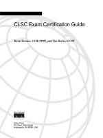
quick review of TCP/IP and IP addressing. Figure 1-1, below, illustrates the primary
function of a router in a small IP network.
Router 2
File Server
14.2.9.10
Router 1
User Host
190.20.2.12
Wide Area
N
etwor
k
LAN 2
14.2.6.0
LAN 3
14.2.9.0
LAN 1
190.20.2.0
Figure 1-1 – A Simple Network with Two Routers
If the user host (top left) needs to send a message to the file server (bottom right), it
simply creates a packet with address 14.2.9.10, and sends the packet over LAN 1 to
its gateway, Router 1. Consulting its internal routing table, Router 1 forwards the
packet to Router 2. Consulting its own routing table, Router 2 sends the packet over
LAN 3 to the File Server. In practice, the operation of any large network depends on
the routing tables in all of its constituent routers. Without robust routing, most
modern networks cannot function. Therefore, the security of routers and their
configuration settings is vital to network operation.
Version 1.0j UNCLASSIFIED 7
Router Security Configuration Guide UNCLASSIFIED
In addition to directing packets, a router may be responsible for filtering traffic,
allowing some data packets to pass and rejecting others. Filtering is a very important
responsibility for routers; it allows them to protect computers and other network
components from illegitimate or hostile traffic. For more information, consult
Sections 3, 4, and 6.
8 UNCLASSIFIED Version 1.0j
UNCLASSIFIED Introduction
1.2. Motivations for Providing Router Security Guidance
Routers provide services that are essential to the correct, secure operation of the
networks they serve. Compromise of a router can lead to various security problems
on the network served by that router, or even other networks with which that router
communicates.
! Compromise of a router’s routing tables can result in reduced
performance, denial of network communication services, and exposure of
sensitive data.
! Compromise of a router’s access control can result in exposure of network
configuration details or denial of service, and can facilitate attacks against
other network components.
! A poor router filtering configuration can reduce the overall security of an
entire enclave, expose internal network components to scans and attacks,
and make it easier for attackers to avoid detection.
! On the other hand, proper use of router cryptographic security features can
help protect sensitive data, ensure data integrity, and facilitate secure
cooperation between independent enclaves.
In general, well-configured secure routers can greatly improve the overall security
posture of a network. Security policy enforced at a router is difficult for negligent or
malicious end-users to circumvent, thus avoiding a very serious potential source of
security problems.
There are substantial security resources available from router vendors. For example,
Cisco offers extensive on-line documentation and printed books about the security
features supported by their products. These books and papers are valuable, but they
are not sufficient. Most vendor-supplied router security documents are focused on
documenting all of the security features offered by the router, and do not always
supply security rationale for selecting and applying those features. This guide
attempts to provide security rationale and concrete security direction, with pertinent
references at the end of each section identifying the most useful vendor
documentation. This guide also provides pointers to related books, vendor
documents, standards, and available software.
Version 1.0j UNCLASSIFIED 9
Router Security Configuration Guide UNCLASSIFIED
1.3. Typographic and Diagrammatic Conventions Used in this Guide
To help make this guide more practical, most of the sections include extensive
instructions and examples. The following typographic conventions are used as part
of presenting the examples.
! Specific router and host commands are identified in the text using Courier
bold typeface: “to list the current routing table, use the command
show ip
route
.” Command arguments are shown in Courier italics: “syntax for a
simple IP access list rule is
access-list number permit host
address
.”
! Sequences of commands to be used in a configuration are shown
separately from the text, using Courier typeface. The exclamation point
begins a comment line, usually a remark about the line that follows it.
! set the log host IP address and buffer size
logging 14.2.9.6
logging buffered 16000
! Transcripts of router sessions are shown separately from the text, using
Courier typeface. Input in the transcript is distinguished from output, user
input and comments are shown in Courier bold typeface. Elision of long
output is denoted by two dots. In some cases, output that would be too
wide to fit on the page is shown with some white space removed, to make
it narrower.
Central> enable
Password:
Central# ! list interfaces in concise format
Central# show ip interface brief
Interface IP Address OK? Method
Ethernet 0/0 14.2.15.250 YES NVRAM
Ethernet 0/1 14.2.9.250 YES Manual
.
.
Central# exit
! IP addresses will be shown in the text and in diagrams as A.B.C.D, or as
A.B.C.D/N, where N is the number of set bits in the IP netmask. For
example, 14.2.9.150/24 has a netmask of 255.255.255.0. (In general, this
classless netmask notation will be used where a netmask is relevant.
Otherwise, the bare address will be used.)
! Cisco IOS accepts the shortest unique, unambiguous abbreviation for any
command or keyword. For commands that are typed very frequently, this
guide uses the abbreviations commonly employed in the Cisco
documentation and literature. For example, the interface name
ethernet
is commonly abbreviated “
eth” and the command configure terminal
is commonly abbreviated “
config t”.
10 UNCLASSIFIED Version 1.0j
UNCLASSIFIED Introduction
Discussions of network structure and security frequently depend on network
diagrams. This guide uses the following set of icons in all of its diagrams.
Router2
This icon represents a router. Each line
connected to a router icon represents a
network interface on that router. Each router
is presumed to have an administrative console
line connection, which is not shown.
Server
Workstation
Computers on the network are represented
with one of these two icons.
Small LAN
12.34.56.0/24
A local-area network (LAN) segment, such as
an Ethernet, is represented by a horizontal or
vertical bus, with several connections.
Network
This icon represents a LAN or a wide-area
network over which routers communicate.
Such networks normally include other routers,
and may include bridges, switches, link
encrypters, and other network hardware.
Version 1.0j UNCLASSIFIED 11
Router Security Configuration Guide UNCLASSIFIED
1.4. Structural Overview
The various parts of this guide are designed to be fairly independent; readers may
want to skip directly to the sections most immediately useful to them. The list below
describes the major sections. References are included at the end of each section.
! Section 2 reviews some background information about TCP/IP networking
and network security, and describes some simple network security threats.
! Section 3 presents a security model for routers, and defines general goals
and mechanisms for securing routers. Security mechanisms must be
applied in support of security policy; this section describes some areas that
a router security policy should address, along with a discussion of
relationships between router security and overall network security.
! Section 4 details the methods and commands for applying security to
Cisco routers, using recent versions of the Cisco IOS software. It is
divided into six main parts:
! securing access to the router itself,
! securing router network services,
! controlling and filtering using a router,
! configuring routing protocols security,
! security management for routers, and
! network access control for routers.
! Section 5 describes advanced security services that some routers can
provide, with a focus on Cisco routers’ capabilities. The three main topics
of this section are IP security (IPSec), SSH, and using a Cisco router as a
simple firewall.
! Section 6 presents testing and troubleshooting techniques for router
security. It is essential for good security that any router security
configuration undergoes testing, and this section presents both vendor-
independent and Cisco-specific testing techniques.
! Section 7 previews some security topics that are not yet crucial for router
configuration, but which may become important in the near future.
! Section 8 consists of four diverse appendices:
! tips for quickly improving the security of a router
! how to apply parts of this guide to LAN switches and other
network hardware
! overview of the Cisco IOS software family and versions, and
! router security glossary.
! Section 9 provides a list of resources, collected from all the sections of the
guide, including pointers to web sites and security tools.
12 UNCLASSIFIED Version 1.0j
UNCLASSIFIED Introduction
How to Use This Guide
Several different roles are involved in securing a network, and each may need some
information about router security. The paragraphs below offer roadmaps for using
this guide for several different network security roles.
For network security planners and system security designers, the high-level view of
router security is more important than the details of Cisco router commands. Read
the sections listed below if your role is security planner or security designer.
! Section 2 – for a review of TCP/IP, network, and router operational
concepts
! Section 3 – for general router security principles
! Section 4.1 through 4.3 – for an idea of what Cisco routers can do for
network security
! Section 5 – for information about Cisco router VPN and firewall
capabilities
! Section 7 – for a preview of potential future issues
For network administrators involved in the daily operation of a network with Cisco
routers, the detailed instructions for locking down a router are the most important
part of this guide. Read the sections listed below if your role is network
administrator.
! Section 2 – for a review, if necessary
! Section 3 – for the security principles behind the advice in Section 4
! Section 4 – for detailed instructions on configuring Cisco routers
! Section 5.1, 5.2 – for instructions on configuring IPSec on Cisco
routers
! Section 5.4 – for a quick guide to using SSH for Cisco administration
! Section 8.1 – for advice for quickly securing a Cisco router
! Section 8.2 – for instructions on applying this guide to LAN switches
! Section 8.3 – for information on Cisco IOS versions and upgrades
! Section 9 – for an overview of recommended references and tools
For network security analysts or administrators trying to improve the security posture
of a network as quickly as possible, this guide offers detailed advice and direction.
Read the sections listed below if you goal is to quickly lock down a router.
! Section 8.1 – for quick tips that will greatly improve router security
! Section 4.1 – for explicit directions on router access security
! Section 4.3 – for advice and guidance on setting up filtering
! Section 4.4 – for routing protocol security instructions (unless the
routers are using static routes exclusively)
Version 1.0j UNCLASSIFIED 13
Router Security Configuration Guide UNCLASSIFIED
14 UNCLASSIFIED Version 1.0j
UNCLASSIFIED Background and Review
2. Background and Review
This section reviews some background information about TCP/IP networking, router
hardware architecture, router software architecture, and network security. In order to
keep this section brief, it glosses over a lot of issues. To compensate for that
briefness, the reference list at the end of the section includes a long list of other
useful sources of background information. Readers with a good grasp of network and
router fundamentals may want to skip this section, but since it is relatively brief, why
not humor the author and read on.
2.1. Review of TCP/IP Networking
As mentioned in Section 1.1, on a small computer network, it is feasible to use
simple broadcast or sequential (token) mechanisms for moving data from point to
point. A local area network is composed of a relatively small number of hosts
connected over a relatively small physical area. “Relatively small” is the important
phrase here. To give some meaning to the term “relatively,” consider that a 10BaseT
Ethernet (10 megabit per second using twisted pair cabling) has a usual maximum of
1024 stations over a maximum cable distance of 2500 meters. For instance a typical
office LAN, using 100BaseT Ethernet, might have 100 computers (and printers)
attached to a switch or set of hubs.
An Ethernet local area network (LAN) is essentially a (logical) bus based broadcast
network; though the physical implementation may use hubs (with a physical star
topology). As one would expect, broadcast LANs must deal with collisions; either by
preventing them or detecting them and taking appropriate action. Token based LANs
avoid collisions by only allowing one host at time to transmit (the host that currently
has the token may transmit).
Standards that relate to LANs are primarily the IEEE 802.x series. For instance,
802.3 is the Media Access Control (MAC) standard for CSMA/CD (the Ethernet
standard); while 802.5 is the MAC standard for Token Ring. Just above the MAC
level is the Logical Link Control (802.2) standard and above that it the High Level
Interface (802.1) standard.
Within a LAN, addressing is done with a MAC address. Between LANs using
TCP/IP addressing is done using IP addresses. If you are lost at this point, keep
reading because much of this will be explained below. If you are still lost at the end
of Section 2, then consider reading parts of some of the books and/or web pages
listed at the end of the section.
2.1.1. Purpose of a Router
In larger, more complex computer networks, data must be directed more carefully. In
almost all cases, large networks are actually composed of a collection of LANs that
are interconnected or “internetworked”. This is where routers come in. Routers take
Version 1.0j UNCLASSIFIED 15
Router Security Configuration Guide UNCLASSIFIED
network data messages from a LAN and convert them into packets suitable for
transmission beyond the LAN on a wide area network (WAN). The goal is almost
always to get these packets to another LAN and ultimately to the correct host on that
LAN. Part of the “conversion” process is to add a packet header. Other routers will
generally only look at a packet’s header information, not at the contents or data in the
packet.
Routers also make decisions about where to send these packets, based on: the
addresses contained within the packet headers and a table of routes maintained within
the router. Updating these routing tables and forwarding data packets between
portions of a network are one of the primary purposes of a router. Building packets
and unwrapping packets are additional router functions performed by the first and
last routers, respectively, that a message passes through. In addition to directing
packets, a router may be responsible for filtering traffic, allowing some packets to
pass through and rejecting others. Filtering can be a very important function of
routers; it allows them to help protect computers and other network components. For
more information about filtering, see Section 3 and Section 4. It is also possible that
at the destination end a router may have to break large packets up to accommodate
the size limits of the destination LAN.
There is no reason that routers cannot be used to send messages between hosts (as
shown in Figure 1-1) but more typically routers are used to connect LANs to each
other or to connect a LAN to a WAN.
Most large computer networks use the TCP/IP protocol suite. In some sense this is
the lingua franca of the Internet. See Section 2.2 for a quick review of TCP/IP and
IP addressing.
2.1.2. Routing Tables
As mentioned, one of tasks of a router is to maintain routing tables which are used to
decide where a packet is to go and thus which interface it should be sent out. In the
past these tables were built and updated by hand and this is referred to as static
routing. In dynamic routing, the router learns about where various addresses are
relative to itself and builds up routing tables based on this information. There are a
number of schemes or routing protocols for routers to acquire and share routing table
information. While a thorough treatment of the details is beyond the scope of this
document, there is a brief discussion of routing protocols is in Section 4.4.
16 UNCLASSIFIED Version 1.0j
UNCLASSIFIED Background and Review
2.2. TCP/IP and the OSI Model
2.2.1. Origin of TCP/IP
The Transmission Control Protocol (TCP) and Internet Protocol (IP) comprise what
is often seen written as TCP/IP. The Defense Advanced Research Projects Agency
(DARPA) originated TCP/IP. Note that the word “Defense” has been deleted and
added back over time. ARPA and DARPA are one and the same organization. The
National Science Foundation (NSF) also contributed to the foundation of the Internet
by taking the DARPA technology and making it available to universities.
As stated above, the Internet essentially runs on TCP/IP protocols. The definitive
source for information on TCP/IP are the RFCs, or “Request for Comments” issued
by the Internet Engineering Task Force as described in Section 2.7.3. Note that in
addition to TCP/IP there are other protocols such as Novell’s IPX (Internetwork
Packet eXchange) that can be used with routers. Also, some routers can be used to
“translate” between different protocols running on either side of themselves.
2.2.2. The OSI Model
After TCP/IP was well-established and other networking protocols, such as DECnet
and Novell’s IPX were operational, the International Standardization Organization
(ISO) developed the Open Systems Interconnection (OSI) seven layer reference
model. These seven layers are described in almost every reference, so in the interest
of space they are merely enumerated here.
Layer 7: Application Layer -
deals with services such as email and file transfer.
Layer 6: Presentation Layer -
deals with formatting, encryption, and compression of data.
Layer 5: Session Layer -
deals with setup and management of sessions between applications.
Layer 4: Transport Layer
deals with end to end error recovery and delivery of complete messages.
Layer 3: Network Layer -
deals with transmission of packets and establishing connections.
Layer 2: Data Link Layer -
deals with transmission of packets on one given physical link.
Layer 1: Physical Layer -
deals with transmission of a bit stream and definition of physical link.
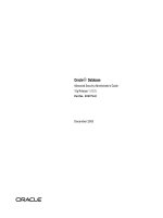
Since the development of TCP/IP preceded the ISO OSI seven layer model, the
“mapping” of TCP and IP to the seven layer model is only an approximation. See
Figure 2-1, Network Layers and Standards, for a visual mapping of TCP/IP to the
Version 1.0j UNCLASSIFIED 17
Router Security Configuration Guide UNCLASSIFIED
OSI model. A collection of various compatible protocol layers is referred to as a
stack.
Application
Presentation
Session
Transport
N
etwor
k
Data Link
Physical
ISO/OSI Model
Application
Transport
N
etwor
k
TCP/IP Model
Logical Link Control
Media Access Control
Physical
IEEE Standards
802.1
802.2
802.3
(Ethernet)
{
TCP or UDP
IP
7
6
5
4
3
2
1
Layer
Data link
Figure 2-1: Network Layers and Standards
Routing occurs at layer three, the Network Layer. To fully understand routing it is
useful to appreciate some of what goes on beneath it at the Data Link Layer, and
some of this is discussed in the following sections. However, the Physical Layer is at
a level of detail well below the concerns of this document. It is concerned with the
transmission of an unstructured bit stream over a physical link. This involves such
details as signal voltage and duration; or optical signaling details for fiber. It also
covers the mechanical aspects of connectors and cables. It may also cover some low
level error control.
18 UNCLASSIFIED Version 1.0j
UNCLASSIFIED Background and Review
2.3. Review of IP Routing and IP Architectures
If one is dealing only with a local area network (LAN), there is generally no need for
routing, routers, TCP/IP, or IP addresses. Within a LAN everything will be handled
by Media Access Control (MAC) addresses and by a LAN protocol such as Ethernet.
At this level, most protocols are defined by Institute of Electrical and Electronics
(IEEE) standards. For instance, IEEE 802.3 is the Ethernet (CSMA/CD) standard,
802.4 is token bus, and 802.5 is token ring. Above the MAC standards, but still
within the OSI Data Link Layer, is the IEEE 802.2 Logical Link Control standard.
The IEEE 802.1 High Level Interface standard corresponds to part of the OSI
Network Layer. If this seems confusing, do not worry about it; it’s not essential to an
understanding of routers.
What is important to keep in mind is that MAC addresses are used within a LAN.
Each device on the LAN will have a something like a network interface card (NIC)
which has a unique MAC address. For example, on an Ethernet LAN each device has
an appropriate Ethernet card, say 100BaseT. The MAC address is appended to the
front of the data before it is placed on the LAN. Each device on the LAN listens for
packets with its address.
Once a message is destined to leave one LAN bound for a trip across a wide area
network (WAN) to another LAN, it must use an IP address. While one can envision
logical connections at various layers in a protocol stack, in reality bits can only move
from one device to another at the Physical Layer. Thus, data begins at an application
relatively high up in a protocol stack and works its way down the stack to the
physical layer. At this point it is transferred to another device and works its way up
the protocol stack at that point. How far up the stack it goes depends on whether that
device is the ultimate recipient of the data or merely an intermediate device. Figure
2-2 illustrates this process. Note that the data may pass through many intermediate
devices on its way from the sending host to the ultimate recipient.
. . .
Sending Host Receiving Host
Router 1 Router
n
Intermediate Network Infrastructure Devices
Figure 2-2: Moving Data through Protocol Stacks
On the way down the stack, each layer adds a relevant header to the packet. The
header is named for the protocol layer that adds it. Each new header is added in front
of all higher layer headers. At the network layer, the IP header added will contain the
Version 1.0j UNCLASSIFIED 19
Router Security Configuration Guide UNCLASSIFIED
destination IP address (in addition to other information). At the data link layer, also
sometimes called the Media Access layer, a new header that contains a MAC address
will be added in front of the IP header. On the way up the stack, a header will be
removed at each layer. Figure 2-3 should help you visualize how headers are added.
Application Data
bytes
TCP
Header
Application
Layer View
Transport
Layer View
bytes
IP
Header
Network
Layer View
bytes
Media
Header
Media
Trailer
Media Access
Layer View
Application
Byte Stream
TCP (or UDP)
Packet
IP
Packet
Ethernet Packet
(or other media format message)
optional
Figure 2-3: Wrapping Lower Level Headers around Data
2.3.1. MAC Addresses
MAC addresses, sometimes referred to as Ethernet addresses are 48 bits long. They
are assigned by the device (or card) manufacturer. Each address is unique and fixed
to a particular piece of hardware. (On some newer devices it is possible to change
them but normally this should not be done.) As stated previously, MAC addresses are
used within a LAN by layer two (data link) protocols.
Traditionally 24 bits uniquely identify the manufacturer and 24 bits act as a serial
number to uniquely identify the unit. Some manufacturers have had more than one
identification number (more than one block of serial numbers). Also, due to mergers
and acquisitions the manufacturer identification is not as “clean” as it once was. Still,
all network interface devices have globally unique addresses unless their PROMs
have been rewritten.
2.3.2. IP Addresses
Currently, IP addresses are 32 bits long. They are used by layer three devices such as
routers. Unlike MAC addresses, IP addresses are hierarchical.
There are four “classes” of IP addresses, referred to as: Class A, Class B, Class C,
and Class D. In addition there a number of special addresses. Special addresses are
used for such things as to broadcast to all hosts on a network or to specify a loopback
packet which will never leave the host. The class determines how much of the 32 bit
address is used to specify the network address and how much is used to specify the
host within that network. The class is determined by the first one to four bits of the
address. Any address beginning with a zero bit is a Class A address. Any address
20 UNCLASSIFIED Version 1.0j
UNCLASSIFIED Background and Review
beginning with bits 10 is a Class B address. Any address beginning with bits 110 is
Class C, and any beginning with bits 1110 is class D.
For any class, it is also possible to take the host portion of the address and further
divide that range into two fields, which specify a subnet address and a host address
respectively. This is done by specifying a parameter called a subnet mask. For a
fuller discussion of subnetting see Albritton’s book [1] or one of the other references
listed in Section 2.7.1.
There are also a set of IP addresses that are reserved for experimental or private
networks; these addresses should not be used on the Internet or other wide-area
networks (see Section 4.3).
In addition to both source and destination addresses, there is a good bit of
information in an IP header. It should be noted that the first 4 bits of an IP header
contain a version number so new versions of the protocol can be implemented.
Moreover the second 4 bits specify the length of the header. Thus it is quite feasible
to introduce longer IP addresses. For a detailed explanation of TCP/IP packet header
formats, see Stevens’ book [10].
Version 1.0j UNCLASSIFIED 21
Router Security Configuration Guide UNCLASSIFIED
2.4. Basic Router Functional Architecture
2.4.1. Why Have a Special Purpose Router?
What are some of the motivations for using a dedicated, purpose-built router rather
than a general purpose machine with a “standard” operating system (OS)? What
justifies this expense, and what justifies the bother of learning yet another system?
The answer, in part, concerns performance: a special purpose router can have much
higher performance than a general purpose computer with routing functionality
tacked onto it. Also, one can potentially add more network connections to a machine
designed for that purpose, because it can be designed to support more interface card
slots. Thus, a special purpose device will probably be a lower cost solution for a
given level of functionality. But there are also a number of security benefits to a
special purpose router; in general, consolidating network routing and related
functions on a dedicated devices restricts access and limits the exposure of those
critical functions.
For one thing, a specialized router operating system (like Cisco’s Internetwork
Operating System or IOS) can be smaller, better understood, and more thoroughly
tested than a general purpose OS. (Note that for brevity, the term IOS will be used in
this document to refer the router’s operating system and associated software, but
hardware other than Cisco would run similar software.) This means that it is
potentially less vulnerable. Also, the mere fact that it is different means that an
attacker has one more thing to learn, and that known vulnerabilities in other systems
are of no help to the router attacker. Finally, specialized routing software enables a
fuller and more robust implementation of filtering. Filtering is useful as a “firewall”
technique, and can also be used to partition networks and prohibit or restrict access to
certain networks or services. Using filtering, some routing protocols can prohibit the
advertisement of routes to neighbors, thus helping protect certain parts of the
network.
2.4.2. Description of Typical Router Hardware
A router is essentially just another computer. So, similar to any other computer, it has
a central processor unit (CPU), various kinds of memory, and connections to other
devices. Generally, a router does not have a hard disk, floppy drive, or CD-ROM
drive. CPU speed and memory size are important considerations for both
performance and capabilities (e.g. some Cisco IOS features require more than the
default amount of memory, and sophisticated security services usually require
substantial computation).
There are typically a number of types of memory in a router possibly including:
RAM, NVRAM, Flash, and ROM (PROM, EEPROM). These are listed roughly in
order of volatility. The mix of types and the amount of each type are determined on
the basis of: volatility, ease of reprogramming, cost, access speed, and other factors.
ROM is used to store a router’s bootstrap software. Non-volatile RAM (NVRAM) is
used to store the startup configuration that the IOS reads when the router boots. Flash
22 UNCLASSIFIED Version 1.0j
UNCLASSIFIED Background and Review
memory stores the IOS (or other router OS), and if there is enough flash it may store
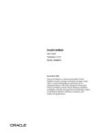
more than one version of IOS. Figure 2-4 shows a simple representation of a notional
router’s hardware structure.
Router
Interface 0 Interface 1 Interface
n
Routing Fabric
CPU
Configuration
Console
Network 0 Network 1 Network
n
. . .
. . .
Figure 2-4: A Notional Router’s Hardware
Interfaces provide the physical connections from a router to networks. Interface types
include Ethernet, fast Ethernet, token ring, FDDI, low-speed serial, fast serial, HSSI,
ISDN BRI, etc. Each interface is named and numbered. Interface cards fit into slots
in a router, and an external cable of the appropriate type is connected to the card. In
addition to a number of interfaces, almost all routers have a console port providing an
asynchronous serial connection (RS-232). Also, most routers have an auxiliary port,
which is frequently used for connecting a modem for router management. [These
hardware ports should not be confused with the concept of network protocol port
numbers, such as the “well known” port numbers associated with particular protocols
and services, such as TCP port 23 being used for Telnet.]
2.4.3. Description of Typical Router Software
Similar to any other computer, a router will run a control program or operating
system (OS). Each router vendor supplies their own router OS. In the case of Cisco
routers, they run Cisco’s Internetwork Operating System (IOS). It is the IOS that
interprets the Access Control List (ACL) and other commands to the router.
The startup or backup configuration is stored in NVRAM. It is executed when the
router boots. As part of the boot process a copy of this configuration is loaded into
RAM. Changes made to a running configuration are usually made only in RAM and
Version 1.0j UNCLASSIFIED 23
Router Security Configuration Guide UNCLASSIFIED
generally take effect immediately. If changes to a configuration are written to the
startup configuration, then they will also take effect on reboot. Changes made only to
the running configuration will be lost upon reboot.
An operational router will have a large number of processes executing to support the
services and protocols that the router must support. All routers support a variety of
commands that display information about what processes are running and what
resources, such as CPU time and memory, they are consuming. Unneeded services
and facilities should be disabled to avoid wasting CPU and memory resources.
Each router should have a unique name to identify it, and each interface should have
a unique network address associated with it. Also, basic security settings should be
established on any router before it is connected to an operational network. These
kinds of considerations are discussed in more detail later in this guide.
24 UNCLASSIFIED Version 1.0j
UNCLASSIFIED Background and Review
2.5. Review of Router-Relevant Protocols and Layers
The following sections are not inclusive of all protocols that might be of interest but
are representative. For more details see Section 4.4, “Routing and Routing
Protocols”. The protocols are grouped according the OSI layer to which they
correspond.
2.5.1. Physical Layer 1
As previously discussed, the physical layer is defined by IEEE standards or similar
standards that define what are primarily physical and electrical characteristics.
2.5.2. Data Link Layer 2
The IEEE and other standards that apply at this layer have also been discussed
previously.
2.5.3. Network Layer 3
IP – the Internet Protocol (IP) provides a specification for packet formatting and an
unreliable, connectionless, best effort delivery of those packets.
ARP – Hosts use the Address Resolution Protocol (ARP) to acquire the MAC address
of other hosts.
2.5.4. Transport Layer 4
TCP – the Transmission Control Protocol (TCP) is a connection-oriented, reliable
protocol. Before transmitting data a connection must be established and after data
transmission is complete the connection must be closed.
UDP – the User Datagram Protocol (UDP) is a connectionless, best effort protocol
with no guarantee of delivery or confirmation of delivery. It has lower overhead than
TCP. When we speak of TCP/IP we are usually implicitly including UDP.
ICMP – the Internet Control Message Protocol (ICMP) provides the mechanisms for
hosts and routers to report network conditions and errors to other hosts and routers.
(For example, the ping command relies on ICMP.)
OSPF – Open Shortest Path First is a relatively complex, fast-converging routing
protocol. It is an interior gateway protocol that uses a link state routing algorithm and
requires that a hierarchy of areas be designed. An area is a logical collection of
routers and networks.
RIP – Routing Information Protocol is a dynamic routing protocol that allows routers
to share network information with each other. It is a distance vector protocol that
Version 1.0j UNCLASSIFIED 25