Microstructural architecture and mechanical properties of empowered cellulose-based aerogel composites via TEMPO-free oxidation
Bạn đang xem bản rút gọn của tài liệu. Xem và tải ngay bản đầy đủ của tài liệu tại đây (7.04 MB, 8 trang )
Carbohydrate Polymers 298 (2022) 120117
Contents lists available at ScienceDirect
Carbohydrate Polymers
journal homepage: www.elsevier.com/locate/carbpol
Microstructural architecture and mechanical properties of empowered
cellulose-based aerogel composites via TEMPO-free oxidation
Hassan Ahmad a, b, Lorna Anguilano a, Mizi Fan a, b, *
a
b
Nanocellulose and Biocomposites Research Centre, College of Engineering, Design and Physical Sciences, Brunel University London, UB8 3PH, United Kingdom
Nanoshift ltd, Tintagel House, 92 Albert Embankment, London SE1 7TY, United Kingdom
A R T I C L E I N F O
A B S T R A C T
Keywords:
Nanocellulose-based aerogel
TEMPO-free oxidation
Microstructure composite mechanism
Crystal structure
This paper describes the development of cellulose-based aerogel composites enhanced via a new refinement
process. The behaviour and microstructure of treated cellulose aerogel composites are examined including, how
the constituents interact and contribute to the overall aerogel composite mechanism. The various forms of cel
lulose such as treated microcrystalline cellulose (MCT), nanofibrillated cellulose (NFC) and nanocrystalline
cellulose (NCC) are also compared. Treated cellulose/Polyvinyl alcohol (PVA) aerogel composites show rein
forced microstructural systems that enhance the mechanical property of the aerogels. The specific modulus of
treated cellulose aerogels could be increased five-fold compared to the stiffness of untreated cellulose aerogels,
reaching specific moduli of 21 kNm/kg. The specific strength of treated cellulose aerogels was also increased by
four folds at 1.7 kNm/kg. These results provide insight into the understanding of the morphology and structure of
treated cellulose-based aerogel composites.
1. Introduction
Aerogels are an interesting class of nanomaterials possessing very
desirable properties including high porosity, low density and low ther
mal conductivity (Aegerter, Leventis, & Koebel, 2012). They are typi
cally produced using a supercritical extraction technique to replace the
liquid component of a gel with a gas (Fricke & Tillotson, 1997) and hold
promise for applications in many industries including absorbents, gas
sensors, energy storage and supercapacitors (Zhai, Zheng, Cai, Xia, &
Gong, 2016; Zhang, Zhai, & Turng, 2017). Their application has thus far
been limited however due to the high costs of the raw materials required
(Cuce, Cuce, Wood, & Riffat, 2014) and the high energy consumption
needed for the supercritical production process. Inorganic aerogels have
also been the primary focus of research into aerogels in the past with
these being very brittle in nature and thus being limited to applications
requiring high strength and toughness (Corma, 1997; Davis, 2002;
Dubinin, 1960). This has encouraged research into the development of
different composite aerogels that offer superior properties and overcome
the current limitations (Ann et al., 2012; Guo et al., 2011; Mohite et al.,
2013; Tan, Fung, Newman, & Vu, 2001).
The use of cellulose within aerogels as part of a composite has been
ăm, 2010; Carlsson
widely studied (Aulin, Netrval, Wågberg, & Lindstro
et al., 2012; Chen, Yu, Li, Liu, & Li, 2011; Chen, Li, et al., 2021; Chen,
ăm, Sharma, Chi, & Hsiao, 2021;
Zhang, et al., 2021; Das, Lindstro
Demilecamps, Beauger, Hildenbrand, Rigacci, & Budtova, 2015; Heise
et al., 2021; Liu, Yan, Tao, Yu, & Liu, 2012; Miao, Lin, & Bian, 2020;
ăkko
ă et al., 2008; Perumal, Nambiar, Moses, & Anandharư
Pă
aa
amakrishnan, 2022; Sehaqui, Zhou, & Berglund, 2011; Zhang, Zhang,
Lu, & Deng, 2012; Zou et al., 2021) with results revealing that such
aerogels that incorporate cellulose fibrils possess higher elasticity and
ăa
ăkko
ă et al., 2008). This is a result of
surface area (Heise et al., 2021; Pa
the high aspect ratio of cellulose fibres and the strong hydrogen bonds
ăa
ăkko
ă
present which create networks that enhance stress transfer (Pa
et al., 2008; Trache et al., 2020). Cellulose, being an abundant, inex
pensive and sustainable natural polymer, presents an attractive material
choice for researchers attempting to create biocompatible and envi
ronmentally friendly products (Dhali, Ghasemlou, Daver, Cass, &
Adhikari, 2021; Fang, Hou, Chen, & Hu, 2019; Perumal et al., 2022;
Reshmy et al., 2022, 2020). Most aerogels that incorporate cellulose
often use the natural fibre as a reinforcement material in nanofibrillar
form (Chhajed, Yadav, Agrawal, & Maji, 2019). Aerogels composed of
larger cellulose fibres as the sole material have also been developed
* Corresponding author at: Nanocellulose and Biocomposites Research Centre, College of Engineering, Design and Physical Sciences, Brunel University London,
UB8 3PH, United Kingdom.
E-mail address: (M. Fan).
/>Received 12 June 2022; Received in revised form 10 September 2022; Accepted 12 September 2022
Available online 16 September 2022
0144-8617/© 2022 The Authors. Published by Elsevier Ltd. This is an open access article under the CC BY-NC-ND license ( />
H. Ahmad et al.
Carbohydrate Polymers 298 (2022) 120117
(MCU). The morphology of the MCU and MCT as well as the mechani
cal properties of the four types of aerogels were investigated. This study
demonstrates that the NC aerogel was found to possess superior me
chanical performance.
using different synthesis processes including that developed by Feng
et al. using Kymene as a cross-linking agent and recycled cellulose from
paper waste (Feng, Nguyen, Fan, & Duong, 2015). The aerogel coated
with methyltrimethoxysilane (MTMS) exhibited high porosity, high oil
absorption capacity, super-hydrophobicity, and very high flexibility
(Feng et al., 2015).
A recently developed patented technique for defibrillating raw
cellulosic material using sonication and 2,2,6,6-Tetramethylpiperidine1-oxyl (TEMPO) free oxidation (Fan, 2016) was used to create an aerogel
before testing its properties. Acid hydrolysis and mechanical defibril
lation are the two primary means of creating nanoscale fibrillated cel
lulose with the hydrolysis process requiring overly high concentrations
of acid and producing relatively low yields (Bondeson, Mathew, &
Oksman, 2006; Salimi, Sotudeh-Gharebagh, Zarghami, Chan, & Yuen,
2019). Mechanical defibrillation, however, can damage the microfibril
structure by reducing the degree of crystallinity as well as molar mass
and may consume a lot of energy depending on the number of passes
through a mechanical homogeniser required (Stenstad, Andresen,
Tanem, & Stenius, 2008). Different pre-treatments have been used as a
method to overcome these limitations presented by mechanical defi
brillation with the main agent used during pretreatment being TEMPONaBr-NaCIO (Isogai, 2021; Pereira, Feitosa, Morais, & Rosa, 2020).
However, TEMPO pretreatment is costly, requires the removal of noncellulose composition and treatment of liquid waste. The TEMPO-free
method has been reported to involve lower costs and waste liquid
while improving the mechanical performance of the isolated fibres. It
involves an oxidation and sonication treatment to defibrillate the raw
fibres before using a centrifuge to isolate the fibrils from the suspension
(Fan, 2016). Moreover, there are different forms of cellulose depending
on the hierarchical scale including micro- and nano-cellulose as well as
different types of structures to consider including crystalline and
fibrillated. In the present study, PVA/Cellulose aerogels were syn
thesised using different hierarchical scales of cellulose namely untreated
microcrystalline cellulose (MCU), treated microcrystalline cellulose
(MCT), nanocrystalline cellulose (NCC) and nanocellulose (NC) which
includes nanofibrillated cellulose (NFC) and NCC. The difference is
described in the experimental work. Treated micro-cellulose (MCT) is a
combination of microcrystalline and branched nanofibrillated cellulose
obtained by a partial conversation of the untreated micro-cellulose
2. Experimental work
Untreated microcrystalline cellulose termed MCU was converted into
four different products including (1) MCT – (thin microcrystalline cel
lulose with branched nano-fibrillated cellulose (NFC)) obtained by
partial conversion of the MCU; (2) NFC – nanocellulose fibrils that are
detached from MCTs and may be linked to other NFCs with branched
nanocrystalline cellulose (NCC); (3) NCC – nanocellulose crystals that
are detached from NFCs and may be linked to other NCCs; (4) NC –
nanocellulose that includes NFCs and NCCs before separation methods
through decanting the supernatant of the centrifuged nanocellulose. A
schematic of the TEMPO-free reaction mechanism is depicted in Fig. 1a
and the resulting SEM images of the two nanocellulose derivative pro
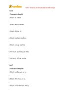
files, NFC and NCC, is shown in Fig. 1b and c, respectively. The width of
the nanocellulose fibrils range between 3 and 20 nm as apparent in
Fig. 1bi and bii. Fig. 1d shows the size distribution by intensity of
nanocellulose using a ‘dynamic light scattering particle size and zeta
potential analyser’ with a sample size of 2 μl (precision of ±1 %). This
was conducted periodically for quality checks with the peak averages
presented in Table 1 and an overall Z-average of 346.5 d⋅nm. Cellulose
types were incorporated with PVA to compare the following aerogel
compositions at 50–50 %: MCU-PVA, MCT-PVA, NCC-PVA and NC-PVA.
Pure MCU, MCT and PVA were also prepared to compare against.
Table 1
Quantitative measurements of the peak sizes in Fig. 1d.
Peak 1
Peak 2
Peak 3
Size (d⋅nm)
% intensity
St Dev (d⋅nm)
361.6
5082
~90
94.9
5.1
n/a
164.5
561.3
n/a
Fig. 1. (a) Schematic of the TEMPO-free NC fabrication process; (b) TEM micrographs of the NFC network with the graphs in bi and bii corresponding to the width of
the fibrils; (c) TEM micrograph of NCC; (d) size distribution of NC analysed by intensity.
2
H. Ahmad et al.
Carbohydrate Polymers 298 (2022) 120117
2.1. Materials
2.4. Characterisations
For analytical and consistency purposes, untreated microcrystalline
cotton cellulose (MCU), 20 μm was purchased from Sigma Aldrich. 98+
% hydrolysed Polyvinyl alcohol (PVA), Mw = 146–186,000 was pur
chased from Sigma Aldrich. Purified deionised water, 0 μS was used
throughout this study via a Biopure 600-unit (Veolia Water Technolo
gies). Sodium hypochlorite (NaClO), 12.5 % and sodium hydroxide
(NaOH), analytical grade 98 % were obtained from Sigma Aldrich and
Fisher Scientific, respectively.
2.4.1. Transmission electron microscopy (TEM)
The suspension structure of cellulose fibres with PVA (MCU-PVA and
MCT-PVA) were examined using a JEOL TEM-2100F microscope oper
ated at 200 kV. Cellulose suspensions were negative stained using 1 %
uranyl acetate before they were drop-cast onto carbon holey film sup
port copper 200 mesh grids. The holey carbon grids had been glowdischarged beforehand for 20 s using an Agar Turbo Carbon Coater set
at 10 mA. Excess sample and stain were wicked away with blotting
paper. Prior to entry into the microscope, samples were plasma cleaned
for 30 s using a Gatan Solarus. Fast Fourier transform (FFT) images were
also obtained to measure distances between atomic planes. TEM lattice
structures were analysed via the GMS 3 Gatan software.
2.2. Treated micro-cellulose (MCT) preparation
MCU was suspended in de-ionised water. The suspension was swelled
and later oxidised using NaOH and NaClO, respectively. The oxidation
reaction was high-shear mixed using a Polytron system PT 2500 E
(Kinematica ag) and an IKA HB 10 heating bath to keep the mixture
mixed at 45 ◦ C, for 30 min. The homogenised slurry was then washed to
pH 7 through cycles of centrifugation, using de-ionised water, followed
by dialysis cycles for 48 h to remove any salts and achieve an electrical
conductance of <100 μS. An approximate yield of 40 % nanocellulose
crystals (NCC) is produced through this process and was consequently
separated through centrifugation for this study. Due to the difficulty of
separating NFC from the MCT, the remaining 60 % nanocellulose fibrils
were termed treated micro-cellulose (MCT) in this paper and were used
for this investigation with consequent aerogel preparation. A sample of
nanocellulose (NC) was also investigated in this study.
2.4.2. Scanning electron microscope (SEM)
The developed aerogel microstructures were characterized through
scanning electron microscopy using a Zeiss Supra 35VP FEG-SEM. Crosssections of the aerogel samples were cut via single-edge razor blades.
The electron high tension (EHT) was set at 5 kV and imaging was carried
out using the SE2 detector. Due to the non-conductive nature, samples
were sputter-coated with a thin layer of gold prior to imaging using a
Polaron-SC7640 Sputter Coater for 2 min.
2.4.3. Apparent density
An analytical balance precise to ±0.005 mg and a digital Vernier
calliper precise ±0.005 mm was used to measure the dry mass and
volume of aerogel samples, respectively. Average densities of four
samples per composition were calculated (dry mass over volume)
(Fig. 5b).
2.3. Aerogel sample preparation
5 wt% stock suspensions of MCU, MCT, NCC, NC and PVA were
prepared. Desired amounts of each cellulose type were suspended in
deionised water by high-shear mixing at 10,000 rpm for 10 min at 22 ◦ C
(ambient temperature) to maximise the cellulose dispersion (Fig. 2) due
to the deagglomeration caused by the electrostatic forces within the
vortex; while PVA was dissolved in deionised water in a round-bottom
flask and stirred at low shear for 2 h in a heating bath at 85 ◦ C. The
combined mixtures were diluted to compose final suspensions of MCUPVA, MCT-PVA, NCC-PVA and NC-PVA at 2.5:2.5 wt% for each
composition. The suspensions were homogenised using the shear mixer
for 10 min at 10,000 rpm under room temperature. The suspension was
later poured on 100 × 100 × 10 mm aluminium foil moulds and frozen
in a liquid nitrogen bath. The frozen samples were freeze-dried (ice
sublimed) at − 51 ◦ C for 120 h via a lyophiliser (Alpha 1–2 LD chamber)
to attain the aerogel composites.
2.4.4. Mercury intrusion porosimetry
A Micromeritics AutoPore V 9620 was used to measure the specific
surface area, bulk density and porosity to characterise the NC-PVA
aerogel measuring the pore size distribution within a range of
0.003–600 μm.
2.4.5. Compressive strength
Aerogel composite samples were cut to 20 × 20 × 10 mm via a
diamond band saw for compression testing. The test was conducted
using an INSTRON 5900 with a 50 kN load cell in a controlled envi
ronment of 23 ◦ C and relative humidity of 45 % in accordance with BS
EN ISO 604. The applied load rate was set to 1 mm/min until a 60 %
strain was realised. The load was applied perpendicular to the axial
grain orientation of the aerogel samples. Averages of compressive
modulus and yield strength of four samples were taken.
2.4.6. X-ray diffraction (XRD)
X-ray diffraction patterns of untreated (MCU, MCU-PVA aerogel) and
Fig. 2. Preparation steps involved in the production of the aerogel composites including, centrifugation of treated cellulose, aerogel suspensions and lyophilisation.
3
H. Ahmad et al.
Carbohydrate Polymers 298 (2022) 120117
treated (MCT, MCT-PVA aerogel) samples were obtained using the
Bragg-Brentano Bruker D8 Advance with Copper tube and LynxEye
position sensitive detector. Samples were scanned between 2θ of 5◦ to
100◦ with increments of 0.01◦ at a scan speed of 1.2 s/step using the Cu
Kα radiation (λ = 1.540596 Å). The XRD patterns were interpreted using
software, Bruker Evaluation Diffrac, Topas and OriginPro.
The Crystallinity Index (CrI) was calculated using the following
equation (Segal, Creely, Martin, & Conrad, 1959):
CrI =
Fig. 3c the vertical lamellae layers are increasingly separating in the
lateral direction, displaying dendritic growth. This is due to the
perpendicular growth of the layers. The thickness of the upper section
can be linked to the freeze-casting stage, whereby the solidification
velocity of the growing ice crystals in the vertical direction decreases
which results in increasing lateral growth. On the other hand, MCU-PVA
aerogel displays a more incoherent structure, containing ordered and
disordered regions. The upper (Fig. 3di) and lower (Fig. 3dii) sections of
Fig. 3d portray a similar effect to the MCT-PVA in that the lamellar
layers grow thicker in the upper region. However, the lamellar layers in
Fig. 3di increase in thickness with wider cavities as opposed to the
occurrence of dendritic growth in Fig. 3ci. Nevertheless, the thickness of
the MCU-PVA layers is still a fraction of the MCT-PVA layers. As shown
in Fig. 3ciii, the MCT-PVA grow notable larger in thickness filling more
of the voids in between in contrast to Fig. 3diii where the layers grow up
to half the thickness of MCT-PVA with slightly wider cavities. The larger
voids are also displayed in the lower (Fig. 3dii) section of MCU-PVA in
comparison to MCT-PVA where the lower (Fig. 3cii) section shows an
increased number of lamellar layers with a large number of bridges inbetween the layers that occupy the majority of the voids. As discussed
earlier, this may be due to the packing arrangement of PVA with the
branched MCT network in suspension. This is desirable in reducing
thermal conductivity, whereby the increased vertical layers increase
lateral heat flow cycles of conduction and convection. The bridges act as
struts providing a more tortuous heat flow path/system as well as giving
way to an increased number of air pockets while reducing the pocket
size. In addition to increasing porosity, the struts also increase the
sturdiness of the composite. Under stress, these bridges may aid in the
energy distribution more efficiently and thus increase the aerogel stiff
ness. The overall microstructural observation of the two aerogels is
linked back to the distribution of their suspensions before freeze-casting.
The incoherent structure of MCU-PVA aerogel (Fig. 3d) is similar to its
irregular and cluttered suspension (Fig. 3b). Similarly, the layered and
dendritic patterns of MCT-PVA aerogel (Fig. 3c) are parallel to the ho
mogenous network structure of its suspension (Fig. 3a). Furthermore, a
notable amount of fibres is perceived in the MCU composite. This may be
due to the bulkiness of the MCU fibres in suspension, whereby the PVA
binds around the low surface area of –OH active sites of MCU fibres. This
means for a 50:50 % ratio of MCU-PVA formulation, excess PVA allows
for more intra-PVA bonding. This may also mean that the PVA in the
MCU aerogel composites contributes more towards the strength of the
composite as the MCU fibres do not form a network and that the needlelike patterns may represent PVA layers. Moreover, the characteristics of
the formed aerogel were assessed in terms of the specific surface area,
bulk density and porosity through mercury intrusion porosimetry. A
sample of NC-PVA aerogel was found to possess a specific surface area of
119.63 m2/g with a median pore diameter of 31.3 nm at 59.82 m2/g and
a bulk density of 0.0613 g/ml with a porosity of 94.5 %. Noticeable
compression of the sample was observed following analysis which
means that the true porosity is expected to be higher than the recorded
result as compression causes pores within the sample to close. In addi
tion, mercury intrusion may destroy the nanofibrillar network of the
cellulose aerogel which may have further reduced the porosity result
recorded from the possible true value (Pircher et al., 2016). The porosity
and specific surface area of the sample confirms it to be an aerogel as
detailed in (Aegerter et al., 2012).
(I002 − Iam )
× 100
I002
3. Results and discussion
3.1. Comparison of MCU and MCT suspensions in PVA dispersions
Fig. 3a and b show TEM micrographs of MCT-PVA and MCU-PVA
suspensions, respectively. It is clear that there is a significant differ
ence between the two suspensions. MCT-PVA (Fig. 3a) shows a ho
mogenous suspension with a large, almost complete web-like network
between the fibres. This is highlighted in the inset image of Fig. 3a. The
larger MCT fibres are small in number however are not separated from
the network of the finer fibrils. Rather they are within the network
structure due to their open surface of branched fibres, which are of
similar aspect ratio to the surrounding finer fibrils, and therefore able to
form a web-like network structure. In comparison, the suspension of
MCU-PVA (Fig. 3b) struggles to form a network structure, displaying
large voids and bulkier fibres. Also, there seem to be several large grey
sheets, depicting PVA, where more voids would otherwise be formed.
This infers that there may also be MCU fibres without much bonding
formed with PVA due to dispersion and/or characteristics of MCU fibres.
Hence, this could be the reason for PVA preferentially bonding with it
self to form the displayed grey sheets even though both suspensions
were shear mixed at 10,000 rpm. These PVA sheets are not displayed in
MCT-PVA. This may very well be due to the more homogenous network
dispersion of MCT as well as the higher aspect ratio of the fibres granting
more active –OH surfaces to bond with PVA. This also infers that the
PVA is binding along the increased surface of the highly dispersed MCT
fibres. Thus, the network of fibres is more strongly linked as displayed by
the darker patches at the joints of the fibre network (inset image of
Fig. 3a). The darker shade of the MCU fibres explains a thicker dimen
sion with a very low aspect ratio compared to the MCT fibres whereby
the shade of grey is marginally darker than the fine fibrils. The overall
reduction in fibre dimension sizes, as well as the branched network
structure of MCT particles, may aid in the packing arrangement with
PVA as the smaller MCT particles may occupy the cavities between the
larger particles during freeze-casting, entrapping longer chains of par
ticles – i.e. forming more continuous and branched solid layers once
lyophilised. This may relate to a more homogenous aerogel density and
hence increased mechanical strength due to enhanced efficiency in load
transfer. This distinction in the dispersity of both suspensions sets a
significant discrepancy in freeze-casting and thus in the final aerogel
morphology.
3.2. Morphology of MCU-PVA and MCT-PVA aerogel composites
The microstructure of the lyophilised cellulose aerogels is an
important consideration in distinguishing the mechanical and physical
properties of the aerogel composites (De France et al., 2021). The
architectural structure of the aerogels determines their effectiveness to
dissipate stress when loaded (Liu et al., 2022). It is apparent from Fig. 3c
and d that both MCU- and MCT-PVA aerogel composites form a layered
architectural lamellar structure though are considerably different. The
full cross-section of MCT-PVA aerogel in Fig. 3c shows an ordered
lamellar structure with a growing tree-like profile. It can be seen that
when comparing the lower (Fig. 3cii) and upper (Fig. 3ci) sections of
3.3. Influence of cellulose treatment on the basal spacing of MCT-PVA
aerogel
The MCU-PVA and MCT-PVA composites and individual raw mate
rials (MCU, MCT, PVA) were analysed using XRD to ascertain whether
the composite manufacturing process incurs structural (d-spacing) or
crystallinity changes (Fig. 4). It can be observed that the cellulose peaks
both of MCU and MCT shift once PVA is inserted into the structure. The
shifts in the graph indicate the changes in d-spacing caused by the
4
H. Ahmad et al.
Carbohydrate Polymers 298 (2022) 120117
Fig. 3. TEM micrographs of (a) MCT-PVA suspension and (b) MCU-PVA suspension; Comparative visual analysis of MCU-PVA and MCT-PVA SEM cross-sectional
images of (c) MCT-PVA aerogel with corresponding separate images of morphological profiles (ci)–(ciii) and (d) MCU-PVA aerogel with corresponding profiles of
separate images (di)–(diii).
5
H. Ahmad et al.
Carbohydrate Polymers 298 (2022) 120117
Fig. 4. XRD spectrums of PVA aerogel composites.
presence of PVA in the structure (Table 2). In particular, it can be
observed that d-spacing decreases both in MCU and MCT, however, the
phenomenon is more pronounced in the MCT (around 3 times larger).
The phenomenon is orientation-dependent, strongest along the (0, 0, 2)
plane in both materials. Moreover, the MCU samples do not show
changes in crystallinity (~80 %) before and after the manufacturing of
the composites as the cellulose and PVA crystallise separately. The full
width at half maximum (FWHM) for the cellulose [0, 0, 2] plane
calculated for each composite and raw material was found to be 1.58 ±
0.03, indicating a crystalline size of ~60 Å. However, small changes can
be observed in the MCT. The crystallinity remains 50 % both for MCT
and for the MCT-PVA composite, however, the cellulose crystallite size
seems to decrease from ~70, with a FWHM of 1.26 for the [0, 0, 2] of the
MCT to ~60 Å with a FWHM of 1.6. Consequently, the results seem to
indicate that the crystalline structure of the MCT allows for larger
compressive stresses to its lattice which induces a relatively wider shift
of d-spacing relative to the untreated cellulose.
PVA has a semi-crystalline nature with a monoclinic unit, whereby it
has both crystalline and amorphous domains in the matrix (Bunn, 1948;
Colvin, 1974). Observing the PVA spectrum against the other composite
spectra, it can be seen that the (0, 0, 1) plane of the PVA is not visible in
MCU-PVA, which means that the peak in MCT-PVA may not be attrib
uted to the PVA (0, 0, 1) peak, rather more directly to the cellulose II of
the MCT peak. The reduction of the (0, 0, 1) peak may be attributed to
the random dispersion of cellulose, inferring that possible distortion of
the structure has occurred in the (0, 0, 1) direction/plane and hence this
would be due to the bonding of PVA with cellulose. A similar reduction
is shown for the (0, 4, 1) peak of PVA in MCU- and MCT-PVA, while the
(1, 1, 0) peak can only be seen in MCT-PVA.
3.4. Compressive property of cellulose-PVA aerogels
The compressive stiffness of aerogel composites is typically depen
dent on the effectiveness of the microstructure in its ability to efficiently
transfer the applied stress and is also dependent on the solid content
which increases the density resulting in a stiffer composite. It can be
seen that the composite graphs follow a generic compressive profile
where the composites yield between 10 and 20 % strain and plastic
deformation occurs until the aerogels start to deform exponentially
beyond ~30 % strain (Fig. 5a). MCT-PVA possesses significantly higher
strength and stiffness compared to MCU-PVA (Table 3). This is despite
MCU-PVA possessing a higher density than MCT-PVA (Fig. 5b). There is
a 3.6-fold higher specific modulus and a 2.9-fold higher specific strength
in MCT relative to the MCU composite (Table 3). The increased stiffness
and strength of MCT-PVA may be a result of the superior microstructure
and bonding interface between MCT and PVA. Evidence for this may be
Table 2
d-value of the PVA aerogel composites.
[HKL]
[0,0,2]
[− 3,1,1],
[− 2,2,2]
[− 1,0,1]
[1,0,1]
Specimen
Composite
Cellulose
Composite
Cellulose
Composite
Cellulose
Composite
Cellulose
MCU-PVA
MCT-PVA
Overall change
d-value
(Å)
Δd
(Å)
d-value
(Å)
Δd
(Å)
d-value
change
3.93
3.95
2.59
2.60
5.81
5.88
5.34
5.39
− 0.03
3.95
3.96
2.64
2.69
5.88
6.07
5.41
5.44
− 0.01
0.03
0.01
0.05
0.01
0.07
0.18
0.07
0.05
− 0.01
− 0.07
− 0.05
6
− 0.05
− 0.19
− 0.03
Δ d MCT/
Δ d MCU
0.4
− 1.9
2.5
− 0.4
H. Ahmad et al.
Carbohydrate Polymers 298 (2022) 120117
Fig. 5. (a) Stress-strain graphs of the different PVA aerogel composites and (b) comparing their densities.
the packing arrangement with PVA. This has affected the architecture of
the developed MCT-PVA aerogel showing ordered lamellar structures
with dendritic growth that displayed superior strength and stiffness to
the MCU-PVA aerogel composite. XRD and SEM explained the effective
load distribution under compressive stress due to the formation of
bridges in the microstructure, alteration of crystallinity in basal spacing
and high aspect ratio. Furthermore, within the MCT-PVA, it was found
that the NC-PVA particularly (which comprises NFC and NCC) possesses
the greatest mechanical properties with a specific modulus of 21 kNm/
kg and specific strength of 1.7 kNm/kg. Overall, this paper presents new
findings in the field of nanocellulose material science including a new
refinement process to enhance the properties of cellulose-based aerogel
composites while also boosting the commercial value in a wide range of
application prospects due to reduced costs associated with the TEMPO
reagent and the effluent treatment. The enhanced microstructural sys
tem leads to strengthened mechanical properties, which in turn im
proves the application of aerogel materials in areas where high strength
and toughness are required.
Table 3
Mean compressive property of the PVA aerogel composites.
Density
(g/
cm3)
MCUPVA
MCTPVA
NCCPVA
NC-PVA
Specific modulus
(E/ρ) (±0.01 kNm/
kg)
Specific strength
(σ/ρ) (±0.01 kNm/
kg)
Yield
strain
(%)
0.062
4.45
0.42
14.88
0.055
15.79
1.24
12.90
0.041
9.13
1.29
18.31
0.051
20.55
1.71
17.13
found in the TEM micrographs (Fig. 3) where the oxidised MCT fibres
appear to possess higher aspect ratios and are more branched as per
MCU bulk fibre. Firstly, the increased aspect ratio due to the splitting of
cellulose fibrils via oxidation adopts additional surfaces of –OH active
sites for PVA bonding to occur. This yields an increased number of PVA
reinforced cellulose layers and thus stiffens the overall macro sheet
layer, which stacks together to form the aerogel composite. Secondly,
the chain of connected branched fibres adopts a more effective load
distribution which increases the stiffness and strength. The increased
stiffness from these phenomena may also contribute to the increased
mean yield stress of the MCT aerogel. It is thought that the increased
stiffness and strength observed in treated cellulose composites could at
least partially be attributed to the increased number of –OH active sites
in correspondence to increasing surface area as well as the branched
network effect.
NC-PVA was also investigated to understand how a composite MCT
and NCC behave. It can be seen from Fig. 5 that the mechanical prop
erties of NC-PVA outperform that of NCC-PVA and MCT-PVA individu
ally. NCC-PVA possessed the lowest density among the four composites
and seems to have lowered the density of the overall NC-PVA composite.
Combining NCC and MCT seems to have improved the underlying
microstructure of the composite possibly through crosslinks between the
two agents and PVA. This has resulted in significantly higher stiffness
and strength while reducing the density of the overall NC-PVA com
posite (Table 3).
CRediT authorship contribution statement
Hassan Ahmad: Conceptualization, Methodology, Software, Vali
dation, Formal analysis, Investigation, Resources, Data curation,
Writing – original draft, Writing – review & editing, Visualization,
Project administration. Lorna Anguilano: Software, Validation, Writing
– review & editing. Mizi Fan: Writing – review & editing, Supervision,
Project administration.
Declaration of competing interest
The authors declare that they have no known competing financial
interests or personal relationships that could have appeared to influence
the work reported in this paper.
Data availability
The data that has been used is confidential.
References
4. Conclusions
Aegerter, M. A., Leventis, N., & Koebel, M. M. (2012). Aerogels handbook.
Ann, M., Meador, B., Malow, E. J., Silva, R., Wright, S., Quade, D.Cakmak, M., … (2012).
Mechanically strong, flexible polyimide aerogels cross-linked with aromatic
triamine. ACS Applied Materials & Interfaces, 4(2), 536–544.
Aulin, C., Netrval, J., Wồgberg, L., & Lindstră
om, T. (2010). Aerogels from nanofibrillated
cellulose with tunable oleophobicity. Soft Matter, 6(14), 3298–3305.
Bondeson, D., Mathew, A., & Oksman, K. (2006). Optimization of the isolation of
nanocrystals from microcrystalline cellulose by acid hydrolysis. Cellulose, 13(2),
171–180.
The behaviour and structure of their suspensions and the developed
aerogels have been thoroughly investigated to determine their physical
and mechanical properties. MCT-PVA suspensions showed expansive
robust network structures due to the homogenous network dispersion of
MCT as well as the higher aspect ratio of the fibres in comparison to
MCU granting more active –OH surfaces to bond with PVA and adding to
7
H. Ahmad et al.
Carbohydrate Polymers 298 (2022) 120117
Liu, S., Yan, Q., Tao, D., Yu, T., & Liu, X. (2012). Highly flexible magnetic composite
aerogels prepared by using cellulose nanofibril networks as templates. Carbohydrate
Polymers, 89(2), 551–557.
Miao, X., Lin, J., & Bian, F. (2020). Utilization of discarded crop straw to produce
cellulose nanofibrils and their assemblies. Journal of Bioresources and Bioproducts, 5
(1), 26–36. />Mohite, D. P., Mahadik-Khanolkar, S., Luo, H., Lu, H., Sotiriou-Leventis, C., &
Leventis, N. (2013). Polydicyclopentadiene aerogels grafted with PMMA: I.
Molecular and interparticle crosslinking. Soft Matter, 9, 15161530.
Pă
aă
akkă
o, M., Vapaavuori, J., Silvennoinen, R., Kosonen, H., Ankerfors, M., Lindstră
om, T.
Ikkala, O., (2008). Long and entangled native cellulose I nanofibers allow flexible
aerogels and hierarchically porous templates for functionalities. Soft Matter, 4(12),
2492–2499.
Pereira, A. L. S., Feitosa, J. P. A., Morais, J. P. S., & Rosa, M.d. F. (2020). Bacterial
cellulose aerogels: Influence of oxidation and silanization on mechanical and
absorption properties. Carbohydrate Polymers, 250, Article 116927. />10.1016/J.CARBPOL.2020.116927
Perumal, A. B., Nambiar, R. B., Moses, J. A., & Anandharamakrishnan, C. (2022).
Nanocellulose: Recent trends and applications in the food industry. Food
Hydrocolloids, 127, Article 107484. />FOODHYD.2022.107484
Pircher, N., Carbajal, L., Schimper, C., Bacher, M., Rennhofer, H., Nedelec, J. M.
Liebner, F., … (2016). Impact of selected solvent systems on the pore and solid
structure of cellulose aerogels. Cellulose, 23(3), 1949–1966. />10.1007/S10570-016-0896-Z/TABLES/5
Reshmy, R., Philip, E., Madhavan, A., Pugazhendhi, A., Sindhu, R., Sirohi, R.Binod, P., …
(2022). Nanocellulose as green material for remediation of hazardous heavy metal
contaminants. Journal of Hazardous Materials, 424, Article 127516. />10.1016/J.JHAZMAT.2021.127516
Reshmy, R., Philip, E., Paul, S. A., Madhavan, A., Sindhu, R., Binod, P.Sirohi, R., …
(2020). Nanocellulose-based products for sustainable applications-recent trends and
possibilities. Reviews in Environmental Science and Biotechnology, 19(4), 779–806.
/>Salimi, S., Sotudeh-Gharebagh, R., Zarghami, R., Chan, S. Y., & Yuen, K. H. (2019).
Production of nanocellulose and its applications in drug delivery: A critical review.
ACS Sustainable Chemistry and Engineering, 7(19), 15800–15827. />10.1021/ACSSUSCHEMENG.9B02744
Segal, L., Creely, J. J., Martin, A. E., & Conrad, C. M. (1959). An empirical method for
estimating the degree of crystallinity of native cellulose using the X-ray
diffractometer. Textile Research Journal, 29(10), 786–794.
Sehaqui, H., Zhou, Q., & Berglund, L. A. (2011). High-porosity aerogels of high specific
surface area prepared from nanofibrillated cellulose (NFC). Composites Science and
Technology, 71(13), 1593–1599.
Stenstad, P., Andresen, M., Tanem, B. S., & Stenius, P. (2008). Chemical surface
modifications of microfibrillated cellulose. Cellulose, 15(1), 35–45.
Tan, C., Fung, B. M., Newman, J. K., & Vu, C. (2001). Organic aerogels with very high
impact strength. Advanced Materials, 13(9), 644–646.
Trache, D., Tarchoun, A. F., Derradji, M., Hamidon, T. S., Masruchin, N., Brosse, N., &
Hussin, M. H. (2020). Nanocellulose: From fundamentals to advanced applications.
Frontiers in Chemistry, 8, 392. />Zhai, T., Zheng, Q., Cai, Z., Xia, H., & Gong, S. (2016). Synthesis of polyvinyl alcohol/
cellulose nanofibril hybrid aerogel microspheres and their use as oil/solvent
superabsorbents. Carbohydrate Polymers, 148, 300–308. />CARBPOL.2016.04.065
Zhang, C., Zhai, T., & Turng, L.-S. (2017). Aerogel microspheres based on cellulose
nanofibrils as potential cell culture scaffolds. Cellulose, 24(7), 2791–2799.
Zhang, W., Zhang, Y., Lu, C., & Deng, Y. (2012). Aerogels from crosslinked cellulose
nano/micro-fibrils and their fast shape recovery property in water. Journal of
Materials Chemistry, 22(23), 11642–11650.
Zou, Y., Zhao, J., Zhu, J., Guo, X., Chen, P., Duan, G.Li, Y., … (2021). A mussel-inspired
polydopamine-filled cellulose aerogel for solar-enabled water remediation. ACS
Applied Materials and Interfaces, 13(6), 7617–7624. />ACSAMI.0C22584/SUPPL_FILE/AM0C22584_SI_001.PDF
Bunn, C. W. (1948). Crystal structure of polyvinyl alcohol. Nature, 161(4102), 929930.
Carlsson, D. O., Nystră
om, G., Zhou, Q., Berglund, L. A., Nyholm, L., & Strømme, M.
(2012). Electroactive nanofibrillated cellulose aerogel composites with tunable
structural and electrochemical properties. Journal of Materials Chemistry, 22(36),
19014–19024.
Chen, W., Yu, H., Li, Q., Liu, Y., & Li, J. (2011). Ultralight and highly flexible aerogels
with long cellulose I nanofibers. Soft Matter, 7(21), 10360–10368.
Chen, Y., Li, S., Li, X., Mei, C., Zheng, J., Shiju, E.Jiang, S., … (2021). Liquid transport
and real-time dye purification via lotus petiole-inspired long-range-ordered
anisotropic cellulose nanofibril aerogels. ACS Nano, 15(12), 20666–20677. https://
doi.org/10.1021/ACSNANO.1C10093/SUPPL_FILE/NN1C10093_SI_003.MP4
Chen, Y., Zhang, L., Yang, Y., Pang, B., Xu, W., Duan, G.Xu, W., … (2021). Recent
progress on nanocellulose aerogels: Preparation, modification, composite
fabrication,applications. Advanced Materials, 33(11), 2005569. />10.1002/ADMA.202005569
Chhajed, M., Yadav, C., Agrawal, A. K., & Maji, P. K. (2019). Esterified superhydrophobic
nanofibrillated cellulose based aerogel for oil spill treatment. Carbohydrate Polymers,
226, Article 115286. />Colvin, B. G. (1974). Crystal structure of polyvinyl alcohol. Nature, 248(5451), 756–759.
Corma, A. (1997). From microporous to mesoporous molecular sieve materials and their
use in catalysis. Chemical Reviews, 97, 2373–2419.
Cuce, E., Cuce, P. M., Wood, C. J., & Riffat, S. B. (2014). Toward aerogel based thermal
superinsulation in buildings: A comprehensive review. Renewable and Sustainable
Energy Reviews, 34, 273299.
Das, R., Lindstră
om, T., Sharma, P. R., Chi, K., & Hsiao, B. S. (2021). Nanocellulose for
sustainable water purification. Chemical Reviews. />CHEMREV.1C00683/SUPPL_FILE/CR1C00683_SI_001.PDF
Davis, M. E. (2002). Ordered porous materials for emerging applications. Nature, 417,
813–821.
De France, K., Zeng, Z., Wu, T., Nystră
om, G., De France, K., Zeng, Z.Nystră
om, G., …
(2021). Functional materials from nanocellulose: Utilizing structure-property
relationships in bottom-up fabrication. Advanced Materials, 33(28), Article 2000657.
/>Demilecamps, A., Beauger, C., Hildenbrand, C., Rigacci, A., & Budtova, T. (2015).
Cellulose–silica aerogels. Carbohydrate Polymers, 122, 293–300. />10.1016/J.CARBPOL.2015.01.022
Dhali, K., Ghasemlou, M., Daver, F., Cass, P., & Adhikari, B. (2021). A review of
nanocellulose as a new material towards environmental sustainability. Science of the
Total Environment, 775. />Dubinin, M. M. (1960). The potential theory of adsorption of gases and vapors for
adsorbents with energetically nonuniform surfaces. Chemical Reviews, 60(2),
235–241.
M. Fan (2016). Patent No. WO 2016/055782 A1. WIPO.
Fang, Z., Hou, G., Chen, C., & Hu, L. (2019). Nanocellulose-based films and their
emerging applications. Current Opinion in Solid State and Materials Science, 23(4).
/>Feng, J., Nguyen, S. T., Fan, Z., & Duong, H. M. (2015). Advanced fabrication and oil
absorption properties of super-hydrophobic recycled cellulose aerogels. Chemical
Engineering Journal, 270, 168–175.
Fricke, J., & Tillotson, T. M. (1997). Aerogels: Production, characterization, and
applications. Thin Solid Films, 297(1–2), 212–223.
Guo, H., Ann, M., Meador, B., Mccorkle, L., Quade, D. J., Guo, J.Sprowl, G., … (2011).
Polyimide aerogels cross-linked through amine functionalized polyoligomeric
silsesquioxane. ACS Applied Materials & Interfaces, 3(2), 546–552.
Heise, K., Kontturi, E., Allahverdiyeva, Y., Tammelin, T., Linder, M. B., Nonappa, &
Ikkala, O. (2021). Nanocellulose: Recent fundamental advances and emerging
biological and biomimicking applications. Advanced Materials, 33(3), Article
2004349. />Isogai, A. (2021). Emerging nanocellulose technologies: Recent developments. Advanced
Materials, 33(28). />Liu, H., Xu, T., Cai, C., Liu, K., Liu, W., Zhang, M.Du, H., … (2022). Multifunctional
superelastic, superhydrophilic, and ultralight nanocellulose-based composite carbon
aerogels for compressive supercapacitor and strain sensor. Advanced Functional
Materials, 32(26), 2113082. />
8