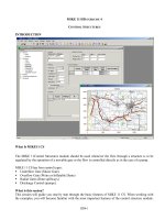
HUAWEI BTS3012 Hardware Structure pdf
Bạn đang xem bản rút gọn của tài liệu. Xem và tải ngay bản đầy đủ của tài liệu tại đây (1.16 MB, 137 trang )
HUAWEI TECHNOLOGIES CO., LTD. All rights reserved
www.huawei.com
Internal
HUAWEI BTS3012
Hardware Structure
ISSUE 2.0
HUAWEI TECHNOLOGIES CO., LTD.
Page 2
All rights reserved
Upon completion of this course, you will be able to:
Know the functions and features of BTS
Master the BTS hardware structure
Master the cable connection of BTS
HUAWEI TECHNOLOGIES CO., LTD.
Page 3
All rights reserved
References
BTS3012 Technical Manual
BTS3012 Installation Manual
BTS3012 User Manual
HUAWEI TECHNOLOGIES CO., LTD.
Page 4
All rights reserved
Chapter 1 Overview
Chapter 1 Overview
Chapter 2 System Components
Chapter 2 System Components
Chapter 3 Signal Processing
Chapter 3 Signal Processing
Chapter 4 Typical configuration
Chapter 4 Typical configuration
HUAWEI TECHNOLOGIES CO., LTD.
Page 5
All rights reserved
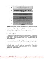
Location
MS: Mobile Station BTS: Base Transceiver Station BSC: Base Station Controller
HLR: Home Location Register AUC: Authentication Center EIR: Equipment Identity Register
MSC: Mobile Switching Center VLR: Visitor Location Register SMC: Short Message Center
VM: Voice Mailbox OMC: Operation and Maintenance Center
PSTN
ISDN
PSPDN
Um Interface
BTS3012
BTS3012
BTS3012
BTS3012
OMC
HLR/AUC/EIR
BSC
MSC/VLR
SMC/VM
A Interface
MAP
M
A
P
TUP,ISUP
MS
MS
MS
HUAWEI TECHNOLOGIES CO., LTD.
Page 6
All rights reserved
Features and Functions (for 12TRXs)
Support GSM800M 、 850M 、 900M 、 1800M 、 1900M
Support networking topology includes star, tree, chain and ring
Support A5/1 and A5/2 encryption/decryption
Support GPRS and EDGE
Support dynamic and static power control
Support the omni-directional coverage and directional coverage
HUAWEI TECHNOLOGIES CO., LTD.
Page 7
All rights reserved
Features and Functions (for 12TRXs)
Double Transceiver Unit (DTRU). A single cabinet can support up to 12 carriers. It can smoothly evolve into WCDMA
Transmit diversity, 4-receive diversity
Support Power Boost Technology (PBT)
BTS3012 can share cabinet with WCDMA base station. The module of WCDMA base station can be inserted in the BTS3012
cabinet
Support more various transmission mode includes E1, STM-1, microwave, and satellite transmission
The DTRU of the BTS3012 can be inserted into BTS30/BTS312 with -48V DC power supply
HUAWEI TECHNOLOGIES CO., LTD.
Page 8
All rights reserved
Features and Functions (BTS3012 - for 18TRXs)Ⅱ
One cabinet can hold up to 18 TRXs and multiple cabinets can hold up to 54 TRXs.
Power Boost Technology (PBT): The maximum output power of the TRX can reach up to 100 W.
The static sensitivity of the TCH/FS is -112.5 dBm (typical value in normal temperature).
Transmit diversity and four-way receive diversity
Baseband frequency hopping and RF frequency hopping
Multiple transmission modes: E1, T1, STM-1, microwave, and satellite transmission
Multiple frequency bands: 850MHz, 900MHz, 1800MHz, and 1900MHz. The cabinet can meet the deployment requirements in different regions.
HUAWEI TECHNOLOGIES CO., LTD.
Page 9
All rights reserved
Features and Functions (for 36TRXs)
Holds up to 36 TRXs per cabinet.
Supports the Hub BTS function.
Supports soft synchronization on the Um interface.
Supports rapid switchover of the ring topology.
Supports Flex Abis networking.
Supports optimized Abis transmission.
Supports local switching.
Supports Abis over IP.
Supports clock over IP.
The static sensitivity of the TCH/FS is -113 dBm (typical value in normal temperature).
Supports various transmission modes: E1, FE, T1, STM-1, microwave, and satellite transmission.
Supports the 900 MHz frequency band.
HUAWEI TECHNOLOGIES CO., LTD.
Page 10
All rights reserved
Chapter 1 Overview
Chapter 1 Overview
Chapter 2 System Components
Chapter 2 System Components
Chapter 3 Signal Processing
Chapter 3 Signal Processing
Chapter 4 Typical configuration
Chapter 4 Typical configuration
HUAWEI TECHNOLOGIES CO., LTD.
Page 11
All rights reserved
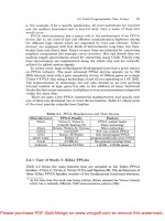
Hardware structure (for 12TRXs)
TMA TMA
DTRU DAFU
Antenna and feeder
subsystem
Forepart of RF
Subsystem
TMA TMA
DTRU
DAFU
TMA TMA
DTRU DAFU
Double transceiver
subsystem
DATU
Um
Interface
DATU
fiber
E1
Abis Interface
M
E
L
C
Common subsystem
NFCB
Metro 100
DTMU
DEMU
E1
BITS
Monitor
TBUS/DBUS/CBUS
MS
FH_BUS
Extension
cabinet
HUAWEI TECHNOLOGIES CO., LTD.
Page 12
All rights reserved
Hardware structure (for 18TRXs)
HUAWEI TECHNOLOGIES CO., LTD.
Page 13
All rights reserved
Hardware structure (for 36TRXs)
HUAWEI TECHNOLOGIES CO., LTD.
Page 14
All rights reserved
BTS3012 Cabinet and Boards (for 12TRXs)
D D D
D
Wiring & Air Inlet
Wiring
D
D
P
U
D
C
O
M
D
C
O
M
D
D
P
U
D
C
O
M
D
T
R
U
D
T
R
U
D
T
R
U
D
T
R
U
D
T
R
U
D
T
R
U
Wiring
FAN
Air Inlet
M
L
C
Power and
EMC
Transmission Unit
D
D
P
U
E
L
C
E
L
C
S
A
C
Transmission Unit
D
T
M
U
D
T
M
U
D
E
M
U
D
C
C
U
D
C
S
U
D
A
T
U
HUAWEI TECHNOLOGIES CO., LTD.
Page 15
All rights reserved
BTS3012 Cabinet and Boards (for 18TRXs & for 36TRXs )
For 18
TRXs
For 36 TRXs
HUAWEI TECHNOLOGIES CO., LTD.
Page 16
All rights reserved
BTS3012 Cabinet and Boards (for 12TRXs)
Abbreviations Description
DTRU Double Transceiver Unit
DTMU Transmission & Timing & Management Unit for DTRU BTS
DCCU Cable Connection Unit for DTRU BTS
DAFU Antenna Front-end Unit for DTRU BTS
DDPU Dual Duplexer Unit for DTRU BTS
DCOM Combining Unit for DTRU BTS
DATU Antenna and TMA Control Unit for DTRU BTS
DMLC Monitor Signal Lightning-Protection Card for DTRU BTS
DELC E1 Signal Lightning-Protection Card for DTRU BTS
DSAC Signal Access Card for DTRU BTS
DCSU
Combined cabinet Signal connection Unit for DTRU BTS
DEMU Environment Monitoring Unit for DTRU BTS
DCTB Cabinet Top Backplane for DTRU BTS
FAN Box NodeB Fan Controlling and monitoring Board
HUAWEI TECHNOLOGIES CO., LTD.
Page 17
All rights reserved
BTS3012 Cabinet and Boards (for 18TRXs)
Subrack Board/Module Full Name Configuration Quantity in One
Cabinet
Full
Configuration
Minimum
Configuration
Common subrack
DTMU Transmission/Timing/Management Unit for DTRU BTS 2 1
DEMU Environment Monitoring Unit for DTRU BTS 1 0
DATU Antenna and TMA Control Unit for DTRU BTS 2 0
DCSU Combined cabinet Signal connection Unit for DTRU BTS 1 1
DCCU Cable Connection Unit for DTRU BTS 1 1
ECMB Enhanced Common Module Backplane for DTRU BTS 1 1
Set-on-top
subrack
DELC E1 Signal Lightning-Protection Card for DTRU BTS 3 1
DMLC Monitor Signal Lightning-Protection Card for DTRU BTS 1 0
DSAC Signal Access Card for DTRU BTS 1 1
DCTB Cabinet Top Backplane for DTRU BTS 1 1
DTRU subrack
DTRU Double-Transceiver Unit 9 1
DTRB Double-Transceiver Unit Backplane 1 1
DAFU subrack
DCOM Combining Unit for DTRU BTS 3 0
DDPU Dual-Duplexer Unit for DTRU BTS 6 0
DFCU Filter Combiner Unit for DTRU BTS 3 0
DFCB Filter Combiner Unit for DTRU BTS 1 0
Fan subrack
Fan box Fan Module 1 1
HUAWEI TECHNOLOGIES CO., LTD.
Page 18
All rights reserved
BTS3012 Cabinet and Boards (for 36TRXs)
Subrack Board/
Module
Full Name Number of Boards or Modules
Configured in a Single Cabinet
Full
Configuration
In Minimum
Configuration
Common
subrack
DTMU Transmission/Timing/Management Unit for DTRU BTS 2 1
DEMU Environment Monitoring Unit for DTRU BTS 1 0
DATU Antenna and TMA Control Unit for DTRU BTS 2 0
DPTU Packet Transmission Unit 2 0
DABB Abis Bypass Board for DTRU BTS 1 0
DCSU Combined cabinet Signal connection Unit for DTRU BTS 1 1
DCCU Cable Connection Unit for DTRU BTS 1 1
DCMB Common Module Backplane for DTRU BTS 1 1
Set-on-top
subrack
DELC E1 Signal Lightning-Protection Card for DTRU BTS 3 1
DMLC Monitor Signal Lightning-Protection Card for DTRU BTS 1 0
DSAC Signal Access Card for DTRU BTS 1 1
DCTB Cabinet Top Backplane for DTRU BTS 1 1
QTRU subrack
QTRU Quadruple-Transceiver Unit 6 1
DTRB Double-Transceiver Unit Backplane 1 1
DAFU subrack DDPU Dual-Duplexer Unit for DTRU BTS 3 1
Power subrack
(only for the
cabinet using
+24 V DC
power)
PSU Power Supply Unit 4 1
Fan subrack Fan box Fan Module 1 1
HUAWEI TECHNOLOGIES CO., LTD.
Page 19
All rights reserved
Common Subsystem
DTMU Transmission/Timing/Management Unit for DTRU BTS
DEMU Environment Monitoring Unit for DTRU BTS
DCSU Combined cabinet Signal connection Unit for DTRU BTS
DCCU Cable Connection Unit for DTRU BTS
DATU Antenna and TMA control Unit for DTRU BTS
DPTU Packet Transmission Unit (For 36 TRXs)
DABB Abis Bypass Board for DTRU BTS (For 36 TRXs)
HUAWEI TECHNOLOGIES CO., LTD.
Page 20
All rights reserved
Comparison of Component Boards
For 12 TRXs For 18 TRXs For 36 TRXs
Component
Boards of
Common
Subsystem
DTMU DTMU DTMU
DEMU DEMU DEMU
DCSU DCSU DCSU
DCCU DCCU DCCU
DATU DATU DATU
ECMB DPTU
DABB
HUAWEI TECHNOLOGIES CO., LTD.
Page 21
All rights reserved
Functions of DTMU
Provides external GPS inputs
Provides BITS synchronized clock inputs
Provides data backup between the active and standby boards
Provides the 10 Mbit/s Ethernet port for maintenance
Supports four E1 inputs by default or eight E1 inputs if required
Controls, maintains, and operates the BTS
Downloads software for the BTS
Provides fault management, configuration management, performance management, and security management
Provides centralized clock distribution and management of the entire BTS, and the hot backup of the clock unit
Provides backup for the E1 ports and the main control unit
Provides eight digital alarm inputs, two of them being lightning arrester failure alarm inputs
Provides four extended digital control signal outputs
Monitors the external fan control board and the power modules
HUAWEI TECHNOLOGIES CO., LTD.
Page 22
All rights reserved
Structure of DTMU
MCK
OML
DBUS
CBUS2
Clock
BIU
DTRU
DTMU
BSC
MCU
MMI
LMT
Abis
External
synchronized clock
Subrack number
and clock
HUAWEI TECHNOLOGIES CO., LTD.
Page 23
All rights reserved
LEDs on the DTMU panel
RUN
ACT
PLL
LIU1
LIU2
LIU3
LIU4
SWT
ALM
RST
MMI
T2M
FCLK
T13M
DTMU
LED Color Description Status Meaning
RUN Green Operating
indicator of
the board
Slow flash (on for 2s and off
for 2s)
The OML is blocked.
Slow flash (on for 1s and off
for 1s)
Normal
Fast flash at unfixed
intervals
The BSC is loading data.
Off There is no power input for the board.
ACT Green Active/stand
by status
indicator
Off Standby board
On Active board
PLL Green Clock status
indicator
Off The clock is abnormal.
On Free-run
Fast flash (on for 0.125s
and off for 0.125s)
Pull-in
Fast flash (on for 0.5s and
off for 0.5s)
Locked
LIU1 Green Transmissio
n status
indicator of
E1 port 1 or
port 5
Off E1 port 1 is normal when SWT is off.
E1 port 5 is normal when SWT is on.
On E1 port 1 near end alarm occurs when SWT is off.
E1 port 5 near end alarm occurs when SWT is on.
Fast flash (on for 0.125s
and off for 0.125s)
E1 port 1 remote end alarm occurs when SWT is
off.
E1 port 5 remote end alarm occurs when SWT is
on.
HUAWEI TECHNOLOGIES CO., LTD.
Page 24
All rights reserved
LEDs on the DTMU panel
RUN
ACT
PLL
LIU1
LIU2
LIU3
LIU4
SWT
ALM
RST
MMI
T2M
FCLK
T13M
DTMU
LED Color Description Status Meaning
LIU2 Green Transmission
status
indicator of
E1 port 2 or
port 6
Off E1 port 2 is normal when SWT is off.
E1 port 6 is normal when SWT is on.
On E1 port 2 near end alarm occurs when SWT is off.
E1 port 6 near end alarm occurs when SWT is on.
Fast flash (on for 0.125s and
off for 0.125s)
E1 port 2 remote end alarm occurs when SWT is off.
E1 port 6 remote end alarm occurs when SWT is on.
LIU3 Green Transmission
status
indicator of
E1 port 3 or
port 7
Off E1 port 3 is normal when SWT is off.
E1 port 7 is normal when SWT is on.
On E1 port 3 near end alarm occurs when SWT is off.
E1 port 7 near end alarm occurs when SWT is on.
Fast flash (on for 0.125s and
off for 0.125s)
E1 port 3 remote end alarm occurs when SWT is off.
E1 port 7 remote end alarm occurs when SWT is on.
LIU4 Green Transmission
status
indicator of
E1 port 4 or
port 8
Off E1 port 4 is normal when SWT is off.
E1 port 8 is normal when SWT is on.
On E1 port 4 near end alarm occurs when SWT is off.
E1 port 8 near end alarm occurs when SWT is on.
Fast flash (on for 0.125s and
off for 0.125s)
E1 port 4 remote end alarm occurs when SWT is off.
E1 port 8 remote end alarm occurs when SWT is on.
SWT Green Indicates the
transmission
status of E1
links
When the DTMU supports
eight E1 routes, the SWT
status is slow flash (on for
10s and off for 10s).
When the SWT is off, LIU1 to LIU4 indicate the
transmission status of E1 port 1 to 4.
When the SWT is on, LIU1 to LIU4 indicate the
transmission status of E1 port 5 to 8.
When the DTMU supports
four E1 routes, the SWT LED
is always off.
LIU1 to LIU4 indicate the transmission status of E1 port 1
to 4.
ALM Red Alarm
indicator
Off No board alarm
On An alarm is generated.
HUAWEI TECHNOLOGIES CO., LTD.
Page 25
All rights reserved
Ports on the DTMU panel
Port Type Function
T2M SMA female connector 2 MHz reference clock, used to test
and tune clock precision
FCLK SMA female connector 216.7 Hz frame clock
T13M SMA female connector 13 MHz reference clock, used to
test and tune clock precision
MMI RJ45 connector Terminal maintenance port