Tài liệu Cryptographic Algorithms on Reconfigurable Hardware- P3 pdf
Bạn đang xem bản rút gọn của tài liệu. Xem và tải ngay bản đầy đủ của tài liệu tại đây (1.65 MB, 30 trang )
3.2 Field Programmable Gate Arrays
39
is.
For example, if for a specific application, bit-level operations are required
and the smallest functional unit is four-bit wide, then a waste of three bits
would occur.
FPGA interconnection has a major role in the performance of an FPGA
device due to the need of fast and efficient communication highways among
the different logic blocks which are organized by rows and columns. Xilinx
devices^ are equipped with four kinds of interconnects: long lines, hex fines,
double fines and direct lines. Direct connect fines are intended for connecting
neighbor components (for example, carry circuitry). Hex and double lines are
medium length interconnects aimed for connecting many CLBs. Finally long
lines interconnects are implemented along the whole chip and are normally
utilized for global system signals.
In recent years, huge technological developments have had a great impact
on FPGA industry. The most advanced FPGA devices operate up to 550
MHz internal clock with a gate complexity of over 10 Milfion gates on a single
Virtex-5 FPGA chip using a technology of just 65 rjm operating at l.OV
[395].
The improvements in technology are not only limited to an ever growing
internal number of logic gates but also to the addition of many functional
blocks like fast access memories, multipliers or even microprocessors integrated
within the same chip.
There are quite a few FPGA commercial manufacturers, and usually each
one of them has developed one or more device families. Table 3.1 shows some
of the most popular manufacturer families.
Table 3.1. FPGA Manufacturers and Their Devices
Manufacturer
Xilinx
Altera
Lattice
Actel
Quick Logic
Atmel
Achronix
FPGA Family
Virtex-5,
Virtex-4,
VirtexII, Spartan HI
Stratix, Stratix II, Cyclone
LatticeXP
Fusion, MTFusion
Eclipse II
AT40KAL
Achronix-ULTRA
Feature
FPGA market leader
6577m technology
9077m technology
first non-volatile FPGA
first mixed-signal FPGA
programmable-only-once FPGA
fine-grained reconfigurable
1.6GHz
- 2.2GHz speed
3.2.1 Case of Study I: Xilinx FPGAs
Table 3.2 shows the main features that are included in the Xifinx FPGA
families: Virtex-5, Virtex-4, Virtex II Pro and Spartan 3E. The architecture of
those Xilinx FPGA families consists of five fundamental functional elements.
^ At the time that this book was being written, Xilinx released the Virtex-5 family
which has a radically different CLB interconnection pattern
[395].
Please purchase PDF Split-Merge on www.verypdf.com to remove this watermark.
40 3. Reconfigurable Hardware Technology
BRAM Blocks
embed ded
multipliers
I/O Blocks (10Bs)
MBB Programmable
llHlBI interconnect
Configurable
Logic Blocks
(CLBs)
Digital Clock
Management (DCMs)
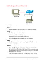
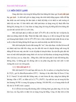
Fig. 3.2. Xilinx Virtex II Architecture
Table 3.2. Xihnx FPGA FamiUes Virtex-5, Virtex-4, Virtex II Pro and Spartan 3E
Feature/family
Logic Cells
BRAM
(ISKbits each)
Multipliers
DCM
lOBs
DSP Slices
PowerPC Blocks
Max. freq.
Technology
Price
Virtex-5
up to 330K
576
32 - 192'
up to 18
up to 1200
32-192
N/A
550MHz
l.OV, 65?7m
copper CMOS
N/A
Virtex-4
12K-200K
36-512
32-512
4-20
240-960
32-192
0-2
500MHz
1.2V, 90r)m,
triple-oxide process
From $345
Virtex II Pro
3K-99K
12-444
12-444
4-12
204-1164
—
0-2
547 MHz
1.5V, 130r7m,
9-layer
CMOS
From $139
Spartan 3 & 3E |
1.7K-74K
4-104
4-104
2-18
63-633
-
-
up to 300MHz
1.2V, 90r/m,
triple-oxide process
From $2 up to $85
'25
X
18 embedded multipliers
• Configurable Logic Block (CLB) and Slice architecture;
• Input/Output Blocks (lOBs);
• Block RAM;
• Dedicated Multipliers and;
• Digital Clock Managers (DCMs).
Those components are physically organized in a regular array as shown in
Fig. 3.2. In the following we explain each one of those five elements^.
^ Virtex-5 devices can be considered second generation FPGA devices. In particu-
lar, a Virtex-5 slice contains four true
6-input
Look Up Tables (LUTs).
Please purchase PDF Split-Merge on www.verypdf.com to remove this watermark.
3.2 Field Programmable Gate Arrays
SLICEM SLICEM
41
Swtdi
Matrix
COUT
A
1
^~—
SHIFT tN
\
/*——
^S
SHIF
T
Silice
X0Y1
Silice
XOYC
i I
TOUT
1.
COUT
Silice
X1Y1
Silice
X1Y0
GIN
*
-m\
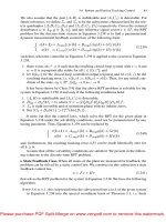
Fig. 3.3. Xilinx CLB
Configuration Logic Blocks (CLBs)
The Configurable Logic Blocs (CLBs) are the most important and abundant
hardware resource of an FPGA. They are typically utilized for both, combi-
natorial and synchronous logic design. Each CLB is composed of four slices^
^
which are interconnected as shown in Fig. 3.3. The slices are grouped by pairs
and each pair is organized by a column with independent carry chain
[395].
All four slices have the following common elements: two Look-Up Tables
(LUTs), two type D fiip-flops, multiplexers, logic circuits for carry handling
and arithmetic logic gates. Both, the left and right pair of shces utihze those
elements for providing logic functions, arithmetic and ROM. Besides that, the
left pair supports two additional functions: data storage using a distributed
RAM and 16-bit shift register functionahty. Fig.3.4 shows the internal struc-
ture of a CLB. The atomic building block of a Virtex CLB is the logic cell
(LC).
An LC includes the Look-Up Table block, carry logic, and a storage
element (flip-flop) as shown in Figure 3.5.
As it was mentioned, a CLB can be configured to work into two modes:
logic) mode and memory mode. As shown in Fig. 3.6, in logic mode, each CLB
Look Up Table behaves as a combinational logic block and a one bit register.
In the case of Xihnx devices those Look Up Tables can be reprogrammed
to any arbitrary combinational logic function of four inputs/one output. In
memory mode. Look Up Table blocks behave as two small pieces of memory
blocks.
^ Slice is a term introduced by Xilinx. It specifies a basic processing unit in a Xilinx
FPGA.
Please purchase PDF Split-Merge on www.verypdf.com to remove this watermark.
42 3. Reconfigurable Hardware Technology
Fig. 3.4. Slice Structure
Logic Cell (LC)
B •
C •
D •
By Pass
Function
Generator
Carry Logic
i
Flip-Flop
—^YQ
Fig. 3.5. VirtexE Logic Cell (LC)
^
^
Combinational
Logic
Combinational
Logic
Kj
ind
1-bit
Reg
1-bit
Reg
16x1 RAM
16x1 RAM
1
[1
1-bit 1
1
Reg 1
1
TM 1
1
1 Reg 1
Fig. 3.6. CLB Configuration Modes
Input/Output Blocks
Input/output Blocks (lOB) provide a bidirectional programmable interface
between the outside world and the internal logic structure of the FPGA device.
Please purchase PDF Split-Merge on www.verypdf.com to remove this watermark.
3.2 Field Programmable Gate Arrays
43
There exist three types of routing possibilities for an lOB: output signal, input
signal and third state (high impedance) signal. Each one of those signals has
their own pair of storage elements that can behave as registers or as latches
[395].
Block RAM
Virtex devices include built-in 18K-bit RAM memory, called BRAM. BRAMs
can be configured in a synchronous manner. BRAMs are intended for storing
big amounts of data, while the distributed RAM is more useful for storing
small amounts of data.
BRAMs are polymorphic blocks in the sense that its width and depth
can be configured. Even multiple blocks can be connected in a back-to-back
configuration in order to create wider and/or deeper memory blocks. A BRAM
block supports several configuration modes, including single or double port
RAM and several possible combination of data/address sizes as is shown in
Table 3.3.
Table 3.3. Dual-Port BRAM Configurations
Configuration
16K X 1 bit
8K X 2 bit
4K X 4 bit
2K X 9 bit
IK X 18 bit
512 X 36 bit
Depth
16Kb
8Kb
4Kb
2Kb
1Kb
512
Data bits
1
2
4
8
16
32
Parity bits
0
0
0
1
2
4
18x18 Bit Multiplier
Xilinx FPGAs have several dedicated multiplier blocks. Those multipliers ac-
cept two 18-bit operands in two's complement form computing their product
also in two's complement form. Such multipliers blocks have been optimized
for performing at a high speed while their power consumption is kept low when
compared with multipliers directly implemented using the CLB resources. The
total number of multipliers varies from device to device as is shown in Table
3.2.
Digital Clock Managers
Digital Clock Managers (DCMs) provide a flexible control over clock fre-
quency, phase shift and skew. The three most important functions of DCMs
are:
To mitigate clock skew due to different arrival times of the clock signal,
Please purchase PDF Split-Merge on www.verypdf.com to remove this watermark.
44 3. Reconfigurable Hardware Technology
to generate an ample range of clock frequencies derived from the master clock
signal and, to shift the signal of all its output clock signals with respect to
the input clock signal.
3.2.2 Case of Study II: Altera FPGAs
Altera offers a wide variety of programmable hardware devices which are
grouped into four categories [4].
• Complex Programmable Logic Devices(CPLDs)
• Low-Cost FPGAs
• High-density FPGAs
• Structured ASICs
CPLDs
Altera's CPLDs include MAX (EPM3032A, EPM3512A) and MAX-H (EPM
240/G, EPM 2210/G) family of devices. They are low complexity, low density
and easy to use CPLD family for which software tools can be downloaded
from Internet and they are free of cost.
Low-Cost FPGAs
Cyclone (EP1C3,EP1C20) and Cyclone-II (EP2C5, EP2C7) family of devices
are considered low cost FPGAs. Their main features include embedded DSP
blocks, on chip memory modules and support for embedded processor (NIGS).
High-Density FPGAs
The category of high density FPGAs from Altera comprises Stratix-II (EP2S15,
EP2S180), Stratix (EPISIO, EP1S80), Stratix^x-H (EP2SGX30C/D, EP2SG-
X130G) and Stratix^x (EPISGXIOC, EP1SGX40G) family of
devices.
Stratix
and Stratix-II families are general purpose FPGAs with fast performance,
large on-chip memory modules, and DSP blocks. StratixGx and StratixGx-H
families, in addition, include integrated transceivers.
Structured ASICs
Structured ASICs comprise Hardcopy (HC1S25, HC240) and Hardcopy-II
(HC210W, HC240) solutions. They have similar design flow as that of Stratix
and Stratix-II respectively. They are low cost structured ASIC solutions with
sufficient number of gates supported by all major EDA vendors.
To provide an idea of what kinds of resources are present in Altera FPGA
devices, let us discuss the structure of the Stratix family of devices. Detailed
Please purchase PDF Split-Merge on www.verypdf.com to remove this watermark.
3.2 Field Programmable Gate Arrays
45
data sheets of Stratix £ts well as all other Altera devices can be consulted
in [4, 207, 208]. The quantitative information presented in this subsection
has been extracted from [4]. Table 3.4 provides a quantitative measure of
Stratix major resources, while Fig. 3.7 shows the physical distribution of those
resources.
Feature
Logic
Elements
M512 RAM
Blocks
M4K RAM
Blocks
M-RAM
Blocks
Total
RAM bits
DSP Blocks
Embedded
1
Multipliers
PLLs
1
Maximum
|l/0 Pins
Table 3.4 . Altera Stratix Devices
Device \
EPISIO
10,570
94
60
1
0.9205M
6
48
6
426
EP1S20
18,460
194
82
2
1.669M
10
80
6
586
EP1S25
25,660
224
138
2
1.945M
10
80
6
706
EP1S30
32,470
295
171
4
3.317M
12
96
10
726
EP1S40
41,250
384
183
4
3.423M
14
112
12
822
EP1S60
57,120
574
292
6
5.215M
18
144
12
1022
EP1S80
79,040
767
364
9
7.427M
22
176
12
1203
Logic Array
Blocks
Phasa-Lock«d ji
Loops X—
•
M512 RAM '
Blocks
DSP Blocks
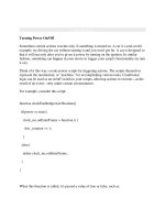
Fig. 3.7. Stratix Block Diagram
As shown in Fig. 3.7, the main building blocks in Stratix devices are the
following:
• Logic Array Blocks (LABs)
Please purchase PDF Split-Merge on www.verypdf.com to remove this watermark.
46
3.
Reconfigurable Hardware Technology
• Memory Blocks
• Digital Signal Processing (DSP) Blocks
• Input/Output Elements (lOEs)
• Interconnects
Logic Array Blocks (LABs)
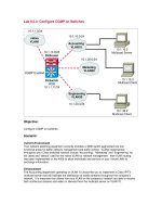
LABs are arranged in rows and columns across the device. Each LAB consists
of 10 Logic Elements (LE). An LE is the smallest unit in Stratix architecture.
It contains four input LUT, carry chain with carry select capabihty and a
programmable register as shown in Fig. 3.8. The LUT serves as a function
generator which can be programmed to any function with four variables. By
using LAB-wide control signal, a dynamic addition or subtraction mode can
also be selected. It is to be noted that number of resources are not fixed for
an LAB in all kind of Altera devices. As an example, a LAB in Stratix-II
architecture comprises 8 Adoptive Logic Modules (ALM) where each ALM
contains a variety of LUT-based resources.
Carryjn 0
Register chain routing
from previous LE
LAB Carry-in
Carryjn 1
62
d3
lb
^ Look-Up
^ Table
(LUT)
Carry
Chain
syn.
load
LAB-wide_
syn.
clear
LAB-wide aload'
LAB-wide enable —'
- Carry_out 0 LAB-wide elk
'ZL
Programmable
Flip Flop
—J
LAB-wide aclr
routing to next
LE
Row.Col,
and direct link
routing
Row.Col,
and direct link
routing
Local routing
Register chain
output
Fig. 3.8. Stratix LE
The Stratix LE can be configured into two modes:
• Normal mode
• Dynamic arithmetic mode
In normal mode, a four input LUT can be used to implement any function.
The normal mode is therefore useful for implementing combinational logic and
general logic functions. In dynamic arithmetic mode, an LE utihzes four 2-
input LUTs which can be mapped to a dynamic adder/subtractor. First two
LUTs perform two summations with possible carry-in and the other two LUTs
compute carry outputs to drive two chains of the carry select circuitry. The
Please purchase PDF Split-Merge on www.verypdf.com to remove this watermark.
3.2 Field Programmable Gate Arrays 47
arithmetic mode is therefore useful for wide range of applications like adders,
accumulators, wide parity functions, etc.
Memory Blocks
Three types of memory blocks are present in Stratix devices as shown in
Fig. 3.7. Those are referred to as M512 RAM, M4K RAM and M-RAM
(MegaRAM) blocks. M512 RAM is a simple dual port memory with sizes
of 512 bits plus parity (576 bits). It can be configured as a maximum 18-bit
wide single or dual port memory at up to 318 MHz. M4K is a true dual port
memory with 4K bits plus parity. It can be configured as a maximum 36-bit
wide dedicated dual port, simple dual or single port memory at 291 MHz.
Several M-RAM blocks can also be located individually in logic arrays across
the device. It is a true dual port memory with 512K bits plus parity (589,824
bits).
A single M-RAM can be configured as a maximum 144-bit wide dedi-
cated dual port, simple dual or single port memory which can operate at 269
MHz.
DSP Blocks
Those are dedicated Stratix resources which are vertically arranged into two
columns in each device. DSP blocks can be configured into either eight 9x9-
bit multiplier, four 18 x 18-bit multiplier or one full 36 x 36 multipher. In
addition, DSP blocks also contain 18 x 18-bit shift registers, Finite Impulse
Response (FIR) and Infinite Impulse Response (HR) filters.
Input/Output Elements (lOEs)
Large number of lOEs can be located at the end of LAB row or column
around the periphery of a Stratix device as shown in Fig. 3.7. Each I/O
element comprises a bi-directional I/O buff"er and six registers for buff'ering
input, output and output-enable signals. Each Stratix I/O pin is fed by an
I/O element and support several single-ended and differential I/O standards.
Interconnects
All LEs within the same LAB, or all LABs within the same device or Memory
blocks or DSP blocks can be interconnected. A single LE can drive 30 other
LEs through locally available fast and direct link interconnects. A direct link
is also used by adjacent LABs, memory and DSP block to drive LABs local
interconnects. The availability of direct hnks helps in reducing row and column
interconnects resulting on higher performance and flexibility.
Please purchase PDF Split-Merge on www.verypdf.com to remove this watermark.
3.
Reconfigurable Hardware Technology
Table 3.5. Comparing Cryptographic Algorithm Realizations on different Platforms
Algorithm FPGA
Throughput
|
year
ASIC
Throughput
I
year
/^Processor
Throughput
year
MD5
5.86 Gbps [156]
2005
2.09 Gbps [312]
2005
1.27Gbps
(est)* [31]
1996
SHA-1 0.9 Gbps
67]
2002
2.006 Gbps [312]
2005
0.678Gbps (est)* [31]
1996
DBS
21.3 Gbps 301]
2003
lOGbps [381]
1999
0.127Gbps [22]
1997
AES 25.1Gbps
113]
2005
7.5Gbps [303]
2001
0.8Gbps[109]
2004
1024-bit RSA
6.1 mS
6]
2005
1.47mS
[210]
2005
22.1mS [294]
2004
ECC (binary)
17.64/iS [54]
2006
190/^8 [313]
2003
475/zS [133]
20011 190MS[313]
|2003|
325/XS
[133]"
from the clock cycle count given in [31]
2004
ECC (prime) 3600AiS [262]
2004
*
Estimated for a 2GHz Pentium IV
3.3 FPGA Platforms versus ASIC and General-Purpose
Processor Platforms
Table 3.5 presents a quick performance comparison of several relevant crypto-
graphic algorithms implemented in three different platforms: Reconfigurable
hardware devices, ASIC and general purpose processors. We included imple-
mentations for hash functions (MD5 and SHA-1), block ciphers (DES and
AES) and pubHc key cryptography (RSA and ECC). All those algorithms will
be studied in the next Chapters.
Referring to Table 3.5, it is noticed that software implementations are al-
ways slower than either, ASIC or FPGA implementations. The performance
gap of software implementations is more noticeable for block ciphers and for
the binary elliptic curve cryptosystem. On the contrary, the best reported
prime elliptic curve cryptosystem is faster than the fastest FPGA design re-
ported in
[262].
We stress that the information included in Table 3.5 is intended for a first
order comparison. As it has been already mentioned, it is extremely difficult
to make fair performance comparisons among designs implemented in differ-
ent platforms using the different technologies available at the time of their
publications. In the rest of this Section we give some more insights about the
advantages/disadvantages of implementing a design on reconfigurable hard-
ware compared with other platform options.
3.3.1 FPGAs versus ASICs
Traditionally, in the design of embedded systems, the Apphcation-Specific In-
tegrated Circuit (ASIC) technology has played a major role for providing high
performance and/or low cost building blocks necessary for the vast majority
of systems during the (usually) large and sinuous design cycle. In 1980 the
usage of reprogrammable components was introduced, and short after that
the first FPGA device was developed by Xilinx. FPGA devices offer shorter
Please purchase PDF Split-Merge on www.verypdf.com to remove this watermark.
3.3 FPGA Platforms versus ASIC and General-Purpose Processor Platforms 49
design cycle because of its ability of providing fast and accurate functionality
testing.
However, the relatively high size and power consumption shown by FPGA
devices has been the most important drawback of that technology towards an
eventual substitution of the virtually ubiquitous ASIC technology. Therefore,
historically FPGAs have been utilized primarily for prototyping development.
In recent years, however, FPGA manufacturers have significantly reduced
the gap that still exist between FPGA and ASIC technology, paving the
way for the utilization of FPGA not only as prototype tools but also as
key components of embedded systems or even, becoming the system itself
[364,
149, 331, 199].
However, the exact size of the performance gap between FPGAs and ASICs
is currently subject of intense analysis and debate. Recently, several experi-
mental results reported in
[192],
seems to suggest that for circuits designed
utihzing the FPGA fabric only (i.e., LUTs and flip flops), an FPGA design is
on average 40 times larger, consumes 12 times more dynamic power and it is
3.2 times slower than a standard ASIC implementation. On the other hand, in
[364] it was developed a low-power FPGA core which was specially tailored for
battery-powered applications such as those found in the automotive industry.
The experimental results show that this solution is competitive with similar
ASIC solutions.
Undoubtedly, new technological challenges must be faced for both, FPGA
and ASIC platforms when the 45 rjm and 32 r]m technologies come to place.
Under this scenario, it is not certain how FPGA new architectures will deal
with the power consumption issue. It might be the case that manufacturers
would need to trade device performance for a more flexible/predictable device
power-consumption
[141].
3.3.2 FPGAs versus General-Purpose Processors
The speedup that one can expect by implementing an algorithm on an FPGA
device rather than using a general purpose processor (i.e. the traditional CPU)
has been well documented in the Hterature [365, 124]. In
[124],
speedups of
one to two orders of magnitude were measured when executing benchmarks
applications in the domains of video and image processing. Roughly speaking,
the same range of speedups has been confirmed in cryptographic algorithms.
From the quahtative point of view, it is interesting to study the main
factors that produce this phenomenon. On the one hand, the typical maximum
clock frequency achieved by FPGA designs fall in the range of 20MHz to
lOOMHz, while embedded microprocessors have frequencies ranging from 300
to 600 MHz and high-end workstation-class processors have frequencies of up
to 3.2GHz. Hence, the clock frequency of general-purpose processors is 10-100
times faster than the typical clock frequency found in FPGA designs. On the
other hand, there are two factors that help to compensate and even overcome
that component, namely,
Please purchase PDF Split-Merge on www.verypdf.com to remove this watermark.
50 3. Reconfigurable Hardware Technology
1.
FPGA Iteration-lev el parallelism^ obtained by, among others, loop-unroUing,
pipeline and sub-pipeline techniques, and;
2.
FPGA Instruction efficiency, obtained by carefully designed datapaths,
the insertion of distributed memory blocks as needed and, taking advan-
tage of the FPGA low granularity, the elimination of several instructions.
Those two factors combine together for obtaining a notable reduction in
the total number of clock cycles required by an FPGA implementation. That
reduction impHes that CPU implementations may require up to 2500 times
more clock cycles than that of FPGA implementations
[124].
In other words,
even though CPU platforms enjoy a much higher operating clock frequency,
this factor is not enough for compensating the enormous clock cycle reduction
that can potentially be obtained in FPGA platforms.
In the context of Moore's Law, an examination of peak floating-point per-
formance trends for FPGA and CPU platforms is presented in
[365].
The
author concludes that although CPUs' performance obeys Moore's law (i.e.,
it doubles every 18 months), FPGA performance is growing at a rate of four
times every two years. For applications using the FPGA new functionality
(embedded multipliers, RAM blocks, etc.) the performance increase rate may
be as high as five times every two years.
3.4 Reconfigurable Computing Paradigm
Reconfigurable computing may be defined as computer processing with highly
flexible computing fabric. The main idea of reconfigurable computing is to
take advantage of the best of two scenarios: flexibility from general purpose
computing and speed from reconfigurable logic.
Some of the reconfigurable computing distinguished features when com-
pared to general purpose microprocessors are
[123]:
• Due to the inherent fine-grained granularity the parallelism tends to be
very high.
• Registers, latches and even distributed RAM blocks can be created and
distributed wherever needed by the data path. This characteristic has a
tremendous impact on the device performance because reduces unneces-
sary re-computations and/or memory accesses.
• The amorphous nature (lack of a fixed architecture) of reconfigurable com-
puting devices, allows the designers to tailor design's data path and control
flow arbitrarily.
FPGAs can be properly used for rapid prototyping algorithms at hard-
ware level. Considering the restrictions of FPGA devices, desirable FPGA
appHcations should belong to one or more of the categories fisted below.
1.
Applications that employ only integer arithmetic or at most low precision
fixed point arithmetic.
Please purchase PDF Split-Merge on www.verypdf.com to remove this watermark.
3.4 Reconfigurable Computing Paradigm 51
2.
Applications that rely on logical operations to make decisions. Compara-
tors,
selectors and multiplexers are good examples of that.
3.
Applications amenable for being decomposed in independent and pipelined
4.
Applications that show regularity in the way they apply a processing.
5.
Applications with locality in the interconnection network they require.
That means that the apphcation modules should only have interconnec-
tions with their neighbors.
Considering FPGA capabilities and limitations some potential applications
for FPGAs are:
1.
Image processing algorithms such as point type operations (grey scale
transformation, histogram equalization, requantization, etc.) and filtering
(template matching, window techniques, convolution/correlation, median
filtering, etc.) seem to be good candidates for FPGA implementation.
2.
Dynamic programming algorithms requiring only integer arithmetic. Dy-
namic programming is in essence a bottom up procedure in which solutions
to all subproblems are first calculated and then these results are used to
solve the whole problem. A good example of this approach is the Floyd's
shortest path algorithm.
3.
Relaxation techniques requiring fixed point arithmetic. The relaxation
technique is an iterative approach useful to many problems, which updates
in parallel at each point and in each iteration based on the data available
in the most recent updating or in the immediate preceding iteration.
4.
Associative retrieval operations. Filling and retrieving data by associa-
tion appears to be a powerful solution to many high volume information
processing elements. An associative processing system is very adequate at
recognition and recall from partial information and has remarkable error
correcting capabilities. The major advantage of associative memory over
RAM is its capability of performing parallel search and parallel compar-
ison operations. Th6?e are many examples of that kind of applications:
pattern matching, artificial inteUigence, computer vision, data encoding,
compression, and every application maintaining a dictionary data struc-
ture.
5.
Highly regular and iterative applications with non-standard word lengths.
Cryptography is a meaningful example of this kind of applications since it
applies basic transformations mostly based on bit-level operations. Those
basic operations are performed in long wordlengths starting from 128 bits
to up 4096 bits or even in wordlengths non-standard, such as 163 and
233 bits (in the case of public-key cryptography). The basic transforma-
tions are repeated iteratively a number of times to process information in
stages. In the following chapters we will explain how to take advantage of
cryptographic algorithm features for reconfigurable computing.
Please purchase PDF Split-Merge on www.verypdf.com to remove this watermark.
52 3. Reconfigurable Hardware Technology
3.4.1 FPGA Programming
The design cycle for programming FPGAs starts with a behavioral descrip-
tion of the design, using either hardware description languages (HDLs) such
as VHDL or Verilog or a schematic design entry. Thereafter, the HDL code
is compiled in order to produce a netlist which represents the mapping of the
HDL code to the actual target device hardware resources. After the first com-
piling step, the netlist is reprocessed in order to perform the place-and-route
process whose main goal is to establish how the different design's modules
are going to be physically allocated and connected. This will create a binary
file which is used for programming or reprogramming the FPGA device. Most
designs included in this book have been compiled using the Xilinx Integrated
Software Environment (ISE) version 8.1i software
[393].
Hardware Description Languages (HDLs) are analogous to other high level
languages (C, C+-f, etc.) with some significant differences. Both types are
processed by a compiler, and both of them are function-oriented languages.
However they differ in the way that the compiled code is executed. HDL
languages are used for formal description of electronic circuits. They describe
circuit's operation, its design, and tests to verify its operation by means of
simulation. Typical HDL compilers tools
[393],
verify, compile and synthesize
an HDL code, providing a list of electronic components that represent the
circuit and also giving details of how they are connected.
3.4.2 VHSIC Hardware Description Language (VHDL)
The Very-High-Speed Integrated Circuit Hardware Description Language
(VHDL) was created by the US Department of Defense in the early 1980s. In
December of 1987, VHDL was adopted as an IEEE Standard
[272].
VHDL is
a functional language that borrows much of its structure from the program-
ming language Ada along with a set of constructs for supporting the inherent
parallelism of hardware designs.
The original version of VHDL, included a wide range of data types such
as,
logical (bit and boolean), numerical, character and time, plus bit and
character. In later versions, the stdJogic data type was introduced, along
with signed and unsigned types to facilitate arithmetical operations, analog
and mixed-signal circuit design extensions
[367].
Furthermore, the designer can know how his/her HDL instruction was
mapped to FPGA components (such as slices, flip-flops, tri-state buffers, etc.).
For example, an if statement in HDL describes a multiplexer or a flip-flop. It
can occur that the frequent use of this statement would insert large number of
multiplexers or flip-flops in a circuit, which is functionally correct but may or
may not be efficient. As a matter of fact, HDL languages have been designed
favoring a hardware designer perspective, in the sense that first the specific
hardware architecture should be envisioned, and then an HDL piece of code
representing it should be written. If for instance a programmer requires a
Please purchase PDF Split-Merge on www.verypdf.com to remove this watermark.
3.5 Implementation Aspects for Reconfigurable Hardware Designs 53
flip-flop functionality then he/she should select a suitable flip flop for the
design and then he/she can write a code for it. That would generate a list of
components for an electronic circuit prior to its implementation providing a
designer complete control over available/used FPGA resources.
3.4.3 Other Programming Models for FPGAs
Several voices, both from the Academia and Industry sectors, have stated
that the main obstacle towards a massive use of reconfigurable computing
lies in the difficulty of programming FPGA devices. After all, HDLs were de-
signed primarily from the perspective of designers trying to describe hardware
structures, which quite often implies that an FPGA programmer should be
primarily a hardware designer.
Considering that, it has been proposed as an alternative to HDLs as design
entry tool to combine high level languages (such as C or C-f-f) with concur-
rency primitives, thus allowing even faster design cycles for FPGAs than what
is now possible using traditional HDLs [119, 189, 39, 229].
Table 3.6 shows some of the commercial software tools currently available
in the market.
Table 3.6. High Level FPGA Programming Software
Vendor
Celoxica
Mentor Graphics
Impulse Accelerated Tech.
Annapolis Microsystems
Open System C
Initiative (OSCI)
Product
Agility Compiler
Catapult C
Impulse C
Core Fire Design Suite
SystemC
Base Language
Handel-C
C
C
GUI Design Entry
C-f+,
IEEE standard 1666
In other order of ideas, designing a complex system in FPGAs can be
greatly alleviated by using existing pre-designed libraries. Those libraries, fre-
quently called IP (Intellectual Property) cores, have been fully tested and
optimized for performing commonly used building blocks, such as large mul-
tiplexers, counters, divisors, digital filters and so forth.
3.5 Implementation Aspects for Reconfigurable
Hardware Designs
3.5.1 Design Flow
In general, most FPGA design tools consist of six basic steps [390] as shown
in Fig. 3.9. Those steps must not be executed in a specific order but they can
Please purchase PDF Split-Merge on www.verypdf.com to remove this watermark.
54 3. Reconfigurable Hardware Technology
Design Entry
FPGA Synthesis
FPGA Place & Route
o
Functional Simulation
Circuit Analysis
FPGA Programming
Fig. 3.9. Design flow
be repeated to improve design's performance. A short description of each step
is provided below.
1.
Design Entry : There are two standard ways to specify an FPGA design,
namely,
• Design Entry through HDLs (Hardware Description Languages): A de-
signer can describe an FPGA design in high-level abstract language
like VHDL (Very high speed integrated circuit Hardware Description
Language) or Verilog. Those languages are ideal to build state ma-
chines, combinational logic, complex and large designs. Most software
tools have sophisticated compilers that can efficiently translate HDL
specifications to FPGA hardware resources.
• Design Entry through Schematic: An FPGA design can also be de-
scribed by using library components of the devices through a graphi-
cal interface. It is easy to optimize a circuit for speed/area and conse-
quently it saves time and efforts of the design tool in hardware map-
ping, placement and routing, etc. However, it is hard to debug and
modifications to the design are not straightforward as compared to
design entry through HDLs.
2.
Functional verification and simulation: In this step, the logical cor-
rectness of an FPGA design is validated. Once that the design has been
specified, either by using HDLs or schematic design entry, it is necessary
to verify if such description meets the design specifications.
3.
FPGA synthesis: Synthesis converts a design entry specification into
gates/blocks of an FPGA device. A netlist of basic gates is prepared from
HDL/schematic design entry, which is further optimized at gate level.
The next step is to map that netlist into IPPGA real resources. This is an
important step based on design entry. When writing HDL code or using
Please purchase PDF Split-Merge on www.verypdf.com to remove this watermark.
3.5 Implementation Aspects for Reconfigurable Hardware Designs 55
schematic device's libraries, an FPGA designer should always take into
account the basic structure of the target device.
4.
FPGA place and route: Place and route selects the optimal physi-
cal positioning of elementary design blocks and minimal interconnection
distance among them. Place and route tools normally use device vendor
specifications. Usually they provide hand-placement and also automatic
features for optimizing critical paths either for speed or for area.
5.
Circuit analysis: Circuit analysis evaluates different design performance
metrics. Timing verification is made which may differ from functional
simulation as it provides logical correctness taking into account all circuit
delays occurring in the real device. Similarly, a power analysis evaluation
provides an estimation of the design power consumption.
6. Programming FPGA device: Programming FPGA implies download-
ing bit stream codes from the last design steps onto the target FPGA
device. Universal programming tools work with FPGAs from different
vendors. However there are dedicated programming tools bounded only
with a single family of FPGA devices.
3.5.2 Design Techniques
It has been observed that better design techniques for both design entry and
design implementation play a crucial role for optimizing circuit's performance.
A short description of some of those optimizing techniques is given below.
Design Strategy
Design strategy is application dependent. For some time critical applications,
timing performance is the most important requirement regardless other factors
such as hardware resources or device cost. On the contrary, other applications
may require a design architecture as compact as possible or with a certain
functionality.
Block cipher cryptographic algorithms have an iterative nature, where n
iterations (or rounds) having the same functionality must be executed. It is
therefore possible to implement either just one round and consume n cycles
(iterative looping), or n rounds of the algorithm (using a pipeline structure) in
order to achieve high timing performances. The designer choice will be made
depending on design's minimum requirements in terms of speed and area.
Fig. 3.10 shows a basic methodology usually followed when implementing
an FPGA design.
Choice of Target Device
Choosing the target device (FPGA) depends on the design strategy. As it
is shown in Table 3.1, an ample spectrum of FPGA devices are available in
Please purchase PDF Split-Merge on www.verypdf.com to remove this watermark.
56
3.
Reconfigurable Hardware Technology
Fig. 3.10. Hardware Design Methodology
the market from various manufacturers. The basic structure of all FPGAs is
similar, however some models offer additional features like built-in-memories,
built-in-arithmetic functions, etc. As it is shown in Table 3.2 for Xilinx de-
vices,
different functionality and sizes are available depending on the device's
cost.
For example, in the case of block cipher designs it may be useful to select
an FPGA device that has embedded Block RAMs (BRAMs) on it. As it was
explained above, BRAMs are fast access memories and might be excellent
choices for a straightforward implementation of the characteristic
S-box
blocks
of symmetric ciphers. Alternatively, S-Boxes can be implemented using the
FPGA CLB fabric configured in memory mode.
In short, the selection of an FPGA depends upon the design size and design
requirements.
Design Analysis
Design/algorithm analysis helps reducing the design's size and critical path
delays. It might not be a good idea to directly implement a fast software code
in hardware. Software codes are often optimized for high granularity proces-
sors,
for example, 8, 16 or 32 bit general-purpose microprocessors. Due to
its inherent low granularity, hardware implementations quite often can bene-
fit from a bit-level parallelism only limited by data dependencies or resource
limitations. For instance, let us consider an instruction from a software code
optimized for a 32-bit word-size general-purpose microprocessor:
work - [((left > 16) | right) & Ox OOOOFFFF];
That requires 16 right shifts, one logical XOR and then one logical AND
with
Ox
OOOOFFFF.
In software platforms, we have no option but to execute
an XOR operation for the 16 most significant bits of 32-bit 'left' and 'right'
registers.
On the contrary, in hardware description languages, the same instruction
can be implemented almost for free, just caring for language notations. One
Please purchase PDF Split-Merge on www.verypdf.com to remove this watermark.
3.5 Implementation Aspects for Reconfigurable Hardware Designs 57
of the best options is to eliminate the AND operation and 16 logical Shifts by
executing instead an XOR operation directly applied to the 16 most significant
bits of left and right registers, that is,
work = left[31:16] 0 right[31:16]
Selecting FPGA Resources
An FPGA designer can pick multiple options for performing a function. For
example, two choices for implementing a 2-bit multiplexer are shown in Fig-
ure 3.11.
SELECT^
A>^
B>+-
^
-OUT
SELECT
'OUT
(a) (b)
Fig. 3.11. 2-bit Multiplixer Using (a) Tristate Buffer, (b) LUT
Figure 3.11.a shows usage of tri-state buffers for a multiplexer. A large
number of tri-state buffers are available in FPGAs and it seems logical to make
use of them. However, experience shows that, using large number of tri-state
buffers slows down the circuit. This tends to require the physical distribution
of tri-state buffers all around FPGA, which requires long routing paths. A
multiplexer can also be implemented using LUTs as shown in Figure 3.11.b.
Using adjacent LUTs for an n to 1 multiplexer would be useful when a circuit
must be optimized for speed.
Similarly, some FPGA devices contain built-in memory modules. It would
be useful to utilize those memories as they provide faster access to the data as
compared to distributed memories in FPGAs which are formed using several
LUTs.
Hardware Approach
A careful selection and usage of the design tools results useful in our method-
ology for obtaining better performances. The design tools by Xilinx
[390],
Altera [3], Synopsis Galaxy Design Platform
[351],
LeonardoSpectrum and
ModelSim by Mentor Graphics [231, 230], etc. provide several useful features
for getting design improvements. Better placement of the components or bet-
ter routing of the architecture modules can be helpful in cutting critical path
delays in the circuit.
Please purchase PDF Split-Merge on www.verypdf.com to remove this watermark.
58 3. Reconfigurable Hardware Technology
3.5.3 Strategies for Exploiting FPGA Parallelism
Achieving high-speed implementations for cryptographic algorithms is an ex-
citing task requiring deep considerations at every stage of the design. De-
sign strategies should therefore not only be based on the best implementing
techniques on reconfigurable platforms but also on trying to innovate in the
theoretical side by improving the standard transformations of cryptographic
algorithms. In this sense, the designs included in this book try to take as
much advantage as possible of the hardware inherent parallelism while keep-
ing as low as possible the hardware resource requirements. In the following
we discuss various strategies used by designers to implement cryptographic
algorithms.
Iterative Looping (IL)
An iterative looping design (IL), implements only one round and n iterations
of the algorithm are carried out by feeding back previous round results as
shown in Figure 3.12a. It utiUzes less area but consumes more clock cycles
resulting on a relatively low speed encryption.
Loop Unrolling
Architecture with loop unrolling is shown in Figure 3.12b. In a loop unrolling
or pipeline design (PP), rounds are replicated and registers are provided be-
tween the rounds to control the flow of data. The design offers high speed but
area requirements tend to be too high.
multiplexer
register
one f
round i
Combinational
logic
register
n
round
multiplexer
round 1
round 2
round n
(a)
(b)
Fig. 3.12. Basic Architectures for (a) Iterative Looping (b) Loop Unrolling
Please purchase PDF Split-Merge on www.verypdf.com to remove this watermark.
3.6 FPGA Architecture Statistics
59
Inner-Round Pipelining
Figure 3.13a shows an inner-round pipehning architecture where extra reg-
isters are provided at different stages of the same round in such a way that
several blocks of data can be processed by the circuit at the same time. This
approach produces high speed circuits at the cost of more hardware resources
in the form of registers.
Outer-Round Pipelining
Outer-round pipelining is created through loop unrolling by adding extra reg-
isters at different stages of the same round as shown in Figure 3.13b. This
approach directly trades circuit speed with circuit area.
register
one
round
multiplexer
pipeline stage 1
pipeline stage 2
pipeline stage k
register
i
n
rounds!
multiplexer
I
pipeline stage 1=round 1
pipeline stage 2=round 2
pipeline stage n=round n
(a)
(b)
Fig. 3.13. Round-pipelining for (a) One Round (b) n Rounds
Both the iterative and pipeline architectures would be optimized for the
implementation of secret-key ciphers. Pubhc key algorithms exhibit different
nature. They do not have rounds however they maintain a hierarchical struc-
ture that can be further exploited.
3.6 FPGA Architecture Statistics
Just as it occurs with software platform comparisons, comparing FPGA de-
signs is a difficult and a bit ambiguous task. The two single most important
performance metrics usually considered are the time complexity^ sometime
called design throughput and the area complexity.
For combinatorial designs (such as adders, squarers, fully-parallel multipH-
ers,
etc), time complexity is determined from the Maximum Clock Frequency
Please purchase PDF Split-Merge on www.verypdf.com to remove this watermark.
60 3. Reconfigurable Hardware Technology
(MCF), which in turns is proportional to the maximum combinational path
delay. In the case of sequential designs (such as block ciphers, sequential mul-
tipliers, etc.), time complexity must also consider the total number of clock
cycles required before the result is ready. In the case of block cipher designs, it
is customary to consider also how many bits are processed at the same time.
In this work we define the throughput of a given design as follows,
Throughput
Throughput is an important factor to measure timing performances of the
design [82, 103, 382]. Throughput of the design is obtained by multiplying the
allowed frequency for the design with the number of bits processed per cycle.
For cryptographic algorithms, throughput is defined as:
Throughput = ^"""-^a^yofcyTe^"^""^ (b**^^)
The higher the throughput of a design is the better its efficiency.
Area
Design statistics provided by the design software expresses hardware area
occupied by the design. Unfortunately, there is no universal metric to measure
the hardware costs associated with an FPGA based design. After mapping a
design to a particular FPGA device, FPGA compiler provides FPGA resources
utilized by that design.
Following are some common FPGA resources listed by the mapping tool:
• Number of slices
• Number of Slice FHp Flops
• Number of 4-input Look Up Tables (LUTs)
• Number of Input/Output Blocks
• Number of Clocks
• Maximum combinational path delay
• Maximum output required time after clock
• Maximum Clock Frequency (MCF)
• BlockSelect RAMs (BRAMs)
A designer, however, can report hardware area in terms of LUTs as well as
CLB slices. An ideal comparison would be therefore comparing all resources
on the similar FPGA device. A design using dedicated resources of the device
will show less logic resources as compared to other design which implements
the whole logic without using any dedicated unit of the device. It also affects
the throughput statistic. It has been experimentally observed that the imple-
mentation of even the same code on different grades of the same family of
devices influence the final design's throughput. That situation becomes more
Please purchase PDF Split-Merge on www.verypdf.com to remove this watermark.
3.7 Security in Reconfigurable Hardware Devices 61
crucial when the same design targets two different devices by two different
manufactures. In such cases, for the purpose of classifying an FPGA design,
we can ignore some of those factors.
It can be said, as a first approximation, that the fastest design is the one
which achieves fastest speed no matter what type of device has been targeted
for design implementation. However, when considering a compact design (a
design optimized for hardware area), this criterion cannot be applied. The
comparison of two compact designs can be only justified if it is made between
similar devices.
Both area and throughput factors provide a measure for comparing
dif-
ferent designs. Additionally, in order to decide how efficient a design is, we
utilize the following figure of merit.
Throughput/Area
It is the ratio of the above two figures of merits and shows how efficient the
design is with respect to both area and throughput. The ratio is higher in case
of high throughput and less space.
3.7 Security in Reconfigurable Hardware Devices
The selection of an implementation platform in a digital system depends on
many design criteria. Besides the design performance figures such as, system
speed and area costs, there exist other performance and security factors that
should be taken into account such as: physical security (for instance, against
key recovery and algorithm manipulation), flexibility, power consumption and
other secondary factors, that may as well affect the design selections.
Even though there exist a fair amount of papers reporting cryptographic
implementations on FPGA devices, there are not that many papers reporting
the convenience (or not) of utilizing FPGA as a target device for security
applications from a system point of view. In particular, few works report the
resilience of FPGA against physical or system attacks, which are potentially
more dangerous than algorithm attacks [379, 342, 343].
In [380, 379] a comprehensive analysis of FPGA security aspects is given.
Authors conclude that FPGA technology can provide a reasonable level of
security when used properly.
The fourth generation design security of Xilinx Virtex-4 family is equipped
with bit-stream encryption/decryption technology based on 256-bit AES. The
user generates the encryption key and encrypted bit-stream using Xilinx ISE
software. In a second step, during configuration, the Virtex-4 device decrypts
the incoming bit-stream using a decryption logic module with dedicated mem-
ory for storing the 256-bit encryption key
[393].
Please purchase PDF Split-Merge on www.verypdf.com to remove this watermark.
62 3. Reconfigurable Hardware Technology
For the cryptographic apphcations, the most important threat is unautho-
rized access to a confidential cryptographic key, either a symmetric key or the
private key of an asymmetric algorithm^.
FPGA implementations are also vulnerable to side-channel attacks. A side
channel attack is based on information gained directly from the physical im-
plementation. Examples for side channels include: power consumption, timing
behavior, and electromagnetic radiation. Most relevant papers on side-channel
attacks and related defenses have been published in [183, 184, 182, 159, 366,
157,
278).
Power analysis attacks were introduced in 1998 by Kocher et al.
[186].
The main idea behind this attack is to measure the power consumption of the
FPGA device during the execution of a cryptographic operation. Thereafter,
that power consumption can be analyzed in an effort for finding regions in
the power consumption trace of a device that are correlated with algorithm's
secret key.
In
[262],
the first experimental results of power analysis attack on an FPGA
implementation of elliptic curve cryptosystem were presented. RSA, AES and
DES FPGA implementations have also been subjects of attacks in [341, 342,
343].
3.8 Conclusions
In this chapter we presented some of the most relevant aspects related to
FPGA devices considering both, technological and reconfigurable program-
ming aspects.
The material covered in this Chapter includes a brief review of the tech-
nological antecedents that gave birth to FPGA devices. We also studied the
structure of several emblematic FPGA families from the two market lead-
ers,
Xilinx and Altera. We compare the performance of FPGA realizations
against the ones on ASICs and general-purpose processor platforms and we
briefly introduced the main concepts related to the reconfigurable computing
paradigm.
Furthermore, we reviewed several key strategies to achieve good designs
when working with cryptographic applications. As a way to measure area and
time performances for a given design, we defined several metrics and figures
of merit. Finally, several security concerns related to FPGA technology were
outhned.
As it was described in the precedent chapter, most cryptographic algorithms have
been standardized and therefore, they are publicly known.
Please purchase PDF Split-Merge on www.verypdf.com to remove this watermark.
Mathematical Background
The material presented in this Chapter, discusses several relevant mathemat-
ical concepts, fundamental for the understanding of elliptic curve public-key
cryptosystems, the RSA algorithm, etc This material is also useful for a
better understanding of the basic operations involved in the specifications of
Rijndael algorithm (new Advanced Encryption Standard (AES)).
For a more detailed treatment of these aspects, the reader is referred to
Number theory books like [376, 220, 47, 297], and to excellent cryptography
books such as [226, 176, 129, 227, 106, 107]. The material presented in this
chapter was written based on [56, 42, 289].
The rest of this Chapter is organized as follows. In Section 4.1 we give
several basic definitions and theorems of the elementary theory of numbers.
Then, in Section 4.2 we explain the concept of finite field, defining the as-
sociated arithmetic operations. Elliptic curves defined over R are described
in Section 4.3. Thereafter, in Section 4.4, elhptic curves defined over binary
extension fields are discussed in more detail. Several coordinate systems for
representing elliptic curve points are presented in Section 4.5. Then diff"er-
ent schemes for scalar representation are discussed in Section 4.6. Concluding
remarks are given in Section 4.7.
4.1 Basic Concepts of the Elementary Theory of
Numbers
Elementary theory of numbers is perhaps the single most important tool for
developing cryptographic algorithms. Therefore, we start this chapter given
some important definitions, theorems and results relevant to the subject of
cryptography.
Please purchase PDF Split-Merge on www.verypdf.com to remove this watermark.