Mạng không dây 2 pot
Bạn đang xem bản rút gọn của tài liệu. Xem và tải ngay bản đầy đủ của tài liệu tại đây (8.02 MB, 234 trang )
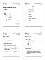
Wireless Ad Hoc & Sensor Networks
- Introduction -
A E
B
S
F
D
WS 2010/2011
C
D
D
Prof. Dr. Dieter Hogrefe
Dr. Omar Alfandi
Dr.
Omar
Alfandi
Outline
• Terms of Lecture
• Lecture Overview
• History
•
Definition
Definition
• Applications
•
Repetition
Physical Layer
•
Repetition
–
Physical
Layer
• Issues
• Summary
2
Terms of Lecture
• Weekly lecture (2 SWS, 5 Credits)
• Problem Sheets (self solution)
• Written Exam: 90 minutes at end of semester
•
Target audience: AI BSc (5++ sem ); AI MSc (1++ sem );
Target
audience:
AI
BSc
(5++
sem
.
);
AI
MSc
(1++
sem
.
);
IT IS MSc (1++ sem.)
A di / id di f th l t ( ft th l t )
•
A
u
di
o
/
v
id
eo recor
di
ng o
f
th
e
l
ec
t
ure
(
a
ft
er
th
e
l
ec
t
ure
)
3
Terms of Lecture
• Learning Goals:
– Understanding, application & critical evaluation of wireless Ad
H&S t kiil
H
oc
&
S
ensor ne
t
wor
k
pr
i
nc
i
p
l
es
•Basics
• Issues
• Current solutions
• Open research questions
Wh t t
•
Wh
a
t
we expec
t
:
– Be prepared for each lecture i.e. read announced chapter (text
book) and lecture slides (published as soon as possible)
book)
and
lecture
slides
(published
as
soon
as
possible)
– Autonomously solve problem sheets, feel free to ask questions
(office hours, email)
4
Terms of Lecture
• Literature
– Ad Hoc Wireless Networks: Architectures and Protocols; C.
Murthy & B. Manoj, Prentice Hall, 2004 ISBN: 013147023X
(First is the basic text book used for the lecture structure)
(First
is
the
basic
text
book
used
for
the
lecture
structure)
– Protocols and Architectures for Wireless Sensor Networks; H.
Karl & A.Willig; 2005; Wiley & Sons; ISBN 0470095102
(Second is also used for Sensor Networks)
– Further Literature and papers, will be announced in lecture
slides.
5
Outline
• Terms of Lecture
• Lecture Overview
• History
•
Definition
Definition
• Applications
•
Repetition
Physical Layer
•
Repetition
–
Physical
Layer
• Issues
• Summary
6
Lecture Overview – OSI Reference Model
Application
• A layer is a collection of
conceptually similar functions that
provide services to the layer above
it and
receives
service from the
Transport Protocol
it
and
receives
service
from
the
layer below it
Network Protocol
• Conceptually two instances at one
layer are connected by a horizontal
Media Access Protocol
layer
are
connected
by
a
horizontal
protocol connection on that layer
Physical Channel
(Radio)
(Radio)
7
Lecture Overview
• Introduction - Today
• External Invited Talk (1 lecture, CS Colloquium)
• Medium Access Schemes (1 lecture)
• Routing and Secure Routing (2 lectures)
• Energy Management (1 lecture)
• Trans
p
ort La
y
er Protocols & QoS
(
1 lecture
)
py ( )
• Security (2 lectures)
• Sensor Networks
(
3 lectures
)
()
• Final written Exam
(
last lecture date
)
()
8
Outline
• Terms of Lecture
• Lecture Overview
• History
•
Definition
Definition
• Applications
•
Repetition
Physical Layer
•
Repetition
–
Physical
Layer
• Issues
• Summary
9
History
500 B.C. 1970‘s 1980‘s
1990‘s
Today
Ad Hoc Voice
ALOHAnet
MANET
MeshBluetooth
Communication
! ! !
PRNET
Hybrid
Sensor
…
SD
King Darius
DARPA
IETF
Ericsson
…
of Persia
10
Outline
• Terms of Lecture
• Lecture Overview
• History
•
Definition
Definition
• Applications
•
Repetition
Physical Layer
•
Repetition
–
Physical
Layer
• Issues
• Summary
11
Definition – Ad Hoc Network
• Ad ho
c
is a Latin phrase which means "for this
[purpose]"
• The purpose is to interconnect computational nodes for
if ti h
i
n
f
orma
ti
on exc
h
ange
It ti i bi li dd t li d
ith t
•
I
n
t
erconnec
ti
on
i
s
b
e
i
ng rea
li
ze
d
d
ecen
t
ra
li
ze
d
, w
ith
ou
t
pre-existing infrastructure, e.g. routers, access points
• Nodes participate in routing of packets, deciding
dynamically
based on connectivity to neighbour nodes
dynamically
,
based
on
connectivity
to
neighbour
nodes
.
12
Definition – Sensor Network
• Sensor from the Latin word sentire which means “to
feel” or “to perceive”
• A Sensor measures a physical quantity and converts it
it i ld ti df b i i t t
i
n
t
o a s
i
gna
l
,
d
es
ti
ne
d
f
or an o
b
serv
i
ng
i
ns
t
rumen
t
S
Ad H
tkit it
•
S
ensors use
Ad
H
oc ne
t
wor
ki
ng
t
o commun
i
ca
t
e
observed information
13
Definition – Cellular vs. Ad Hoc
Cellular Networks
A D
SD
Ad Hoc Multihop Networks
E
A
B
D
C
S
S
D
14
Cellular vs Ad Hoc
Cellular Networks Ad Hoc Wireless Networks
Fixed infrastructure based Infrastructure less
Single-hop wireless links Multi-hop wireless links
Centralized routing Distributed routing
High reliability Frequent path breaks due to mobility
Low complexity mobile hosts Mobile hosts also routers
Geographical reuse of spectrum
Carrier sense bases reuse of
Geographical
reuse
of
spectrum
Carrier
sense
bases
reuse
of
spectrum
Widely deployed, currently 4G Remaining issues, low commercial
dl t id di
df
d
ep
l
oymen
t
, w
id
esprea
d
i
n
d
e
f
ense
15
Outline
• Terms of Lecture
• Lecture Overview
• History
•
Definition
Definition
• Applications
•
Repetition
Physical Layer
•
Repetition
–
Physical
Layer
• Issues
• Summary
16
Applications
• Military Applications
• Transportation Communication
• Wireless Sensor Networks (Monitoring)
• Collaboration/Distributed Computing
•Emer
g
enc
y
O
p
erations
gyp
• Wireless Mesh Networks
•H
y
brid Wireless Networks
y
17
Applications - Military
• Why? Establish communication among a group of
soldiers/vehicles for tactical operations
• Where? Areas with impossible infrastructure set up
• Security is crucial, eavesdropping and other attacks can
compromise information and personel safety.
18
Applications – Transportation (C2C)
• Why? Primary reduce number of lethal accidents.
S d bl ki d f i
S
econ
d
ary ena
bl
e new
ki
n
d
s o
f
serv
i
ces.
• How? Enable Car to Car (C2C) and Car to Infrastructure
(C2I) communication for road safety messages.
19
Applications – Sensor Networks
• Why? Monitoring of physical parameters and
transmitting to a sensor sink
• Where? Health care, home security, military,
environmental monitoring
• Issues: mobility, network size, deployment density,
tit
power cons
t
ra
i
n
t
s
20
Applications - Animal Monitoring
1. Biologists put sensors in
underground nests of
storm petrel
storm
petrel
2. And on 10cm stilts
3. Devices record data
about birds
4. Transmit to research
station
5. And from there via
satellite to lab
21
Applications – Collaboration
• Why? Required instant communication
• Where? Conference (file exchange), Lecture (notes
distribution) using laptops/smart phones
• Properties: Lower security than military, energy
constraints, uni- and multicast.
22
Applications – Emergency Operations
• Why? Required communication for rescue, crowd
control, commando operations activities
• Where? Areas with no/destroyed infrastructure due to
natural calamities, war, etc.
• Properties: self configurable, decentralized, capable of
iiti
vo
i
ce commun
i
ca
ti
on
23
Applications – Wireless Mesh Networks
• Why? Provision of alternate communication capability to
mobile/fixed nodes, opposed to cellular networks.
• Where? Areas with no/low cable coverage or cost
constraints or quick deployment needs.
• Properties: Simple expandability, high availability
24
Applications – Hybrid Wireless Networks
• What? Multi-hop cellular networks
• Why? Exponential growth in subscriber base of cellular
networks, over 4 bn in 2008.
• Properties: mobile nodes are involved in routing, High
capacity/coverage, centric routing topology maintenance
(BTS) P bl
ti d
bil d
(BTS)
,
P
ro
bl
em: energy cons
t
ra
i
ne
d
mo
bil
e no
d
es
25
Applications – Hybrid Wireless Networks
Cellular Multi-Hop Networks
A
D
E
B
S
D
26
Outline
• Terms of Lecture
• Lecture Overview
• History
•
Definition
Definition
• Applications
•
Repetition
Physical Layer
•
Repetition
–
Physical
Layer
• Issues
• Summary
27
Physical Layer - OSI Reference Model
Application
Transport Protocol
Network Protocol
Media Access Protocol
Physical Channel
(Radio)
(Radio)
28
Physical Layer - Spectrum
regulated
1 Mm
300 Hz
10 km
30 kHz
100 m
3 MHz
1 m
300 MHz
10 mm
30 GHz
100 m
3 THz
1 m
300 THz
visible light
VLF LF MF HF VHF UHF SHF EHF infrared UV
ISM
ISM
29
Physical Layer - Frequencies and Regulations
Europe (CEPT/ETSI) USA (FCC) Japan
Mobile
phones
GSM ≈800,1700,
1800 Mh
CDMA ≈ 800 MHz, PDC ≈ 800, 900, 1400
Mh
phones
1800
Mh
z
CDMA, GSM ≈1800 MHz,
1900 MHz
Mh
z
Cordless DECT
PACS ≈1800, 1900 Mhz PHS ≈1900 Mhz
telephones 1880-1900 MHz
JCT ≈200–400Mhz
Wireless
IEEE 802.11
IEEE 802.11
IEEE 802.11
Wireless
LANs
IEEE
802.11
2400-2483 MHz
IEEE
802.11
2400-2483 MHz
IEEE
802.11
2471-2497 MHz
30
Physical Layer - Signal Propagation Ranges
• Straight line propagation
• Transmission range
– communication possible
– low error rate
• Detection range
– detection possible
no comm nication
sender
transmission
–
no
comm
u
nication
• Interference range
no signal detection
distance
detection
it f
–
no
signal
detection
– Signal part of background noise
i
n
t
er
f
erence
31
Physical Layer – Signal Propagation
Free space propagation
PP
rr
= P= P
tt
GG
tt
GG
rr
( λ / 4πd )( λ / 4πd )
22
• Simplest path loss model, a direct-path signal.
• The following definitions are assumed:
–P
r
- The received signal power.
–P
t
- The transmitted signal power.
G
Th i f h i i
–
G
r
-
Th
e ga
i
n o
f
t
h
e rece
i
v
i
ng antenna.
–G
t
- The gain of the transmitting antenna.
–
λ
-
The wavelength of the carrier (i e the center frequency of the
λ
-
The
wavelength
of
the
carrier
(i
.
e
.,
the
center
frequency
of
the
radiated signal)
– d - The distance between the transmitting and receiving antennas.
32
Physical Layer - Antennas
x/y
z
x
y
directed
antenna
side (xz)/top (yz) views
x/y
side view (yz-plane)
x
antenna
y
y
x
x
sectorized
antenna
top view, 3 sector top view, 6 sector
33
Physical Layer - Attenuation by Objects
• Shadowing (3-30 dB):
– textile (3 dB)
– concrete walls (13-20 dB)
– floors (20-30 dB)
• reflection at large obstacles
• scattering at small obstacles
• diffraction at edges
fl ti
tt i
diff ti
hd i
re
fl
ec
ti
on sca
tt
er
i
ng
diff
rac
ti
ons
h
a
d
ow
i
ng
34
Physical Layer - Effects of Mobility
• Channel characteristics change over time and location
– signal paths change
–
distance to sender changes
– obstacles position changes
power
• Fading
short term
short
term fading
long term
fading
–
short
term
– long term
t
• Doppler shift:
change/shift in the frequency
change/shift
in
the
frequency
35
Physical Layer - Modulation and Demodulation
digital
analog
baseband
digital
modulation
data
analog
modulation
radio
signal
101101001
radio transmitter
analog
bbd
radio
carrier
synchronization
decision
digital
data
analog
demodulation
b
ase
b
an
d
signal
101101001
radio receiver
radio
carrier
36
Physical Layer - Digital Modulation
101
• Modulation of digital signals
• Amplitude Shift Keying (ASK):
t
– very simple
– low bandwidth requirements
tibl t i t f
101
–
very suscep
tibl
e
t
o
i
n
t
er
f
erence
• Frequency Shift Keying (FSK):
t
– needs larger bandwidth
•
Phase Shift Keying (PSK):
101
Phase
Shift
Keying
(PSK):
– more complex
– robust against interference
t
37
Outline
• Terms of Lecture
• Lecture Overview
• History
•
Definition
Definition
• Applications
•
Repetition
Physical Layer
•
Repetition
–
Physical
Layer
• Issues
• Summary
38
Issues
• Medium Access Scheme
• Routing
• Multicasting
• Transport Layer Protocols
• Pricing Scheme
• Qualit
y
of Service Provisionin
g
yg
• Self Organization
• Securit
y
y
• Energy Management
• Scalabilit
y
y
39
Outline
• Terms of Lecture
• Lecture Overview
• History
•
Definition
Definition
• Applications
•
Repetition
Physical Layer
•
Repetition
–
Physical
Layer
• Issues
• Summary
40
Summary
• Ad Hoc networks serve the purpose of connecting nodes
instantly, without infrastructure
• Ancient use in natural societies with voice, drums,
trum
p
ets for hi
g
h s
p
eed communication
pgp
• Sensors use ad hoc networks to communicate registered
physical parameters to a monitoring sink
physical
parameters
to
a
monitoring
sink
• Compared to cellular networks ad hoc nodes are more
complex and deal with dynamic topology and resource
constraints
41
Summary
• A vast area of applications is possible for ad hoc
networks
–
Military
– Car2Car
Mesh
–
Mesh
– Sensors
–
…
• Physical Layer has highly special characteristics
• Issues exist in all la
y
ers due to distribution and d
y
namics
yy
• Outlook: Next lecture will tackle properties and issues of
MAC layer and possible solutions
MAC
layer
and
possible
solutions
42
Summary – Next Session
Application
Transport Protocol
Network Protocol
Media Access Protocol
Physical Channel
(Radio)
(Radio)
43
Wireless Ad Hoc & Sensor Networks
Wireless
Ad
Hoc
&
Sensor
Networks
Medium Access Control
Application
Transport Protocol
NkP l
WS 2010/2011
N
etwor
k
P
rotoco
l
Media Access Protocol
Prof. Dr. Dieter Hogrefe
Dr. Omar Alfandi
Media
Access
Protocol
Physical
Channel (Radio)
Dr.
Omar
Alfandi
Physical
Channel
(Radio)
Outline
• Multiple Access Technique
• Designing Issues of MAC protocols
•
Classification of MAC protocols
Classification
of
MAC
protocols
• Protocols examples
•
Characteristics of Link layer protocols
•
Characteristics
of
Link
layer
protocols
• The lower layers in detail
• Summary
2
Media Access Control (Intro.)
• Wireless medium is shared
• Many nodes may need to access the wireless medium to
send or receive messages
• Concurrent message transmissions may interfere with
each other collisions message drops
3
Multiple Access Technique
• Reservation-based (Recall: mobile communication 1)
– FDMA : Frequency Division Multiple Access
–
TDMA : Time Division Multiple Access
– CDMA : Code Division Multiple Access
SDMA :
Space Division Multiple Access
–
SDMA
:
Space
Division
Multiple
Access
• Random
–
ALOHA : University of Hawaii Protocol
ALOHA
:
University
of
Hawaii
Protocol
– CSMA : Carrier Sense Multiple Access
– MACA : Multiple Access with Collision Avoidance
• Random with reservation
– DAMA : Demand Assigned Multiple Access
–
PRMA : Packet Reservation Multiple Access
4
Reservation-based
• FDMA (Frequency Division Multiple Access)
– assign a certain frequency to a transmission channel
–
permanent (radio broadcast), slow hopping (GSM), fast hopping
(FHSS, Frequency Hopping Spread Spectrum)
•
TDMA (Time Division Multiple Access)
•
TDMA
(Time
Division
Multiple
Access)
– assign a fixed sending frequency for a certain amount of time
•
CDMA (Code Division Multiple Access)
CDMA
(Code
Division
Multiple
Access)
• SDMA (Space Division Multiple Access)
–
se
g
ment s
p
ace into sectors
,
use directed antennas
gp ,
– Use cells to reuse frequencies
• Combinations
5
FDD and TDD
• In case of tow communicating parties sharing the
medium:
–
Simplex : one way communication from sender to receive
r
– Duplex : two way communication between two parties
– Frequency division duplex (FDD)
• Combination of two simplex channels with different carrier
frequencies
– Time division duplex (TDD)
•
Time sharing of a single channel achieves quasi
-
simultaneous
Time
sharing
of
a
single
channel
achieves
quasi
simultaneous
duplex transmission
6
Random Access
• However, wireless communication is often much more
ad-hoc
–
New terminals have to register with the network
– Terminals request access to the medium spontaneously
In many cases there is no central control
–
In
many
cases
there
is
no
central
control
Other access methods such as distributed and
non
-
arbitrated = random access
non
arbitrated
=
random
access
7
Multiple Access
Characteristics:
• Shared medium : radio channel is shared by an priori
unknown number of stations
• Broadcast medium: all stations within transmission range
of a sender receive the signal
Challenge:
• Wireless communication channel is prone to errors and
bl hidd / d d bl & i l
pro
bl
ems, e.g.,
hidd
en
/
expose
d
no
d
e pro
bl
ems
&
s
i
gna
l
attenuation
8
Wired vs. Wireless
• Ethernet uses 1-persistent CSMA/CD
– carrier sense multiple access with collision detection
• Sense if the medium is free and start sending as soon as it
becomes free
• While sending listen to the medium to detect other senders
• In case of a collision immediately stop sending and wait for the
random amount of time
•
Problems in wireless networks
•
Problems
in
wireless
networks
– signal strength decreases quickly with distance
–
senders a
pp
l
y
CS and CD
,
but the collisions ha
pp
en at receivers
pp y , pp
– Energy efficiency: having the radio turned on costs almost as
much energy as transmitting, so to seriously save energy one
needs to turn the radio off!
needs
to
turn
the
radio
off!
9
Outline
• Multiple Access Technique
•Desi
g
nin
g
Issues of MAC
p
rotocols
gg p
•
Classification of MAC protocols
Classification
of
MAC
protocols
• Protocols examples
•
Characteristics of Link layer protocols
•
Characteristics
of
Link
layer
protocols
• The lower layers in detail
• Summary
10
Need for MAC Protocols ?
• Popular CSMA/CD (Carrier Sense Multiple
Access/Collision Detection) scheme is not applicable to
wireless networks
• CSMA suffers hidden terminal & exposed terminal
problems
Collision Detection is impossible in wireless
•
Collision
Detection
is
impossible
in
wireless
communication
Specific MAC protocols for the access to the
physical layer
physical
layer
11
Hidden Terminal Problem
• A sends to B, C cannot receive A
• C wants to send to B, C senses a “free” medium (CS
fails)
• collision at B, A cannot receive the collision (CD fails)
• A is “hidden” for C
B
A
C
12
Exposed Terminal Problem
• B sends to A, C wants to send to D
• C has to wait, CS signals a medium in use
• since A is outside the radio range of C waiting is not
necessary
• C is “exposed” to B
B
A
C
D
B
A
C
D
13
Near and Far Terminals
• Terminals A and B send, C receives
– the signal of terminal B hides A’s signal
–
C cannot receive
A
ABC
– This is also a severe problem for CDMA networks
– precise power control required
14
Outline
• Multiple Access Technique
•Desi
g
nin
g
Issues of MAC
p
rotocols
gg p
• Classification of MAC protocols
• Protocols examples
•
Characteristics of Link layer protocols
•
Characteristics
of
Link
layer
protocols
• The lower layers in detail
• Summary
15
Classification of MAC protocols
16
In general (1/2)
• Contention-based protocols:
– A node does not make any resource reservation a priori.
–
Whenever a node receives a packet to be transmitted, it
contends with its neighbour nodes for access
–
Can not provide QoS (Quality of Service) guarantees to session
Can
not
provide
QoS
(Quality
of
Service)
guarantees
to
session
since nodes not guaranteed regular access to the channel
• Contention-based with reservation
– Wireless networks may need to support real-time traffic
Rti hif ibdidthii
–
R
eserva
ti
on mec
h
an
i
sms
f
or reserv
i
ng
b
an
d
w
idth
a pr
i
or
i
– Such protocols can provide QoS support to time-sensitive traffic
sessions
17
In general (2/2)
• Contention-based with scheduling
– These protocols focus on packet scheduling at nodes, and also
hdli d f t th h l
sc
h
e
d
u
li
ng no
d
es
f
or access
t
o
th
e c
h
anne
l
– Used for enforcing priorities among flows whose packets are
q
ueued at nodes
q
– Some of them take into consideration battery characteristics
(remaining battery power)
Oth t l
•
Oth
er pro
t
oco
l
s
18
Outline
• Multiple Access Technique
•Desi
g
nin
g
Issues of MAC
p
rotocols
gg p
• Classification of MAC protocols
•
Protocols examples
Protocols
examples
•
Characteristics of Link layer protocols
•
Characteristics
of
Link
layer
protocols
• The lower layers in detail
• Summary
19
Multiple Access with Collision Avoidance (MACA)
• MACA uses a two step signaling
procedure to address the hidden
ddtilbl
ABCD
RTS
an
d
expose
d
t
erm
i
na
l
pro
bl
ems
• Use short signaling packets for
collision avoidance
CTS
collision
avoidance
– Request (or ready) to send RTS: a
sender re
q
uests the ri
g
ht to send
Data
b
u
s
qg
from a receiver with a short RTS
packet before it sends a data packet
Clear to send CTS: the receiver
Data
s
y
b
u
s
y
–
Clear
to
send
CTS:
the
receiver
grants the right to send as soon as it
is ready to receive
ACK
y
20
MACA (cont.)
• Signaling packets contain
– sender address
–
receiver address
– packet size
•
Network allocation vector (NAV)
•
Network
allocation
vector
(NAV)
• Duration during which other sender have to keep quiet to avoid a
collision
• If control (RTS-CTS) messages collide with each other
or with data packets, a backoff procedure is activated
(backoff is binary exponential)
(backoff
is
binary
exponential)
• Example: Wireless LAN (IEEE 802.11)
21
MACA examples
• MACA avoids the problem of hidden terminals
– A and C want to
dt B
sen
d
t
o
B
– A sends RTS first
–
C waits after receiving
RTS
C
waits
after
receiving
CTS from B
A
B
C
CTSCTS
• MACA avoids the problem of exposed terminals
– B wants to send to A,
dCt D
an
d
C
t
o
D
– now C does not have
to wait as C cannot
RTS
CTS
RTS
receive CTS from A
ABC
CTS
D
22
MACA extensions (1/2)
• MACAW extends MACA : RTS-CTS-DS-DATA-ACK
– DLL (Data Link Layer) acknowledgements
–
An improved backoff mechanism
– DS (Data Sending) message:
•
Say that a neighbour of the sender overhears an RTS but not a CTS
•
Say
that
a
neighbour
of
the
sender
overhears
an
RTS
but
not
a
CTS
(from the receiver)
• In this case it can not tell if RTS-CTS was successful or not
Wh it h th DS it li th t th RTS
CTS
•
Wh
en
it
over
h
ears
th
e
DS
,
it
rea
li
zes
th
a
t
th
e
RTS
-
CTS
was
successful, and it defers its own transmission
23
MACA extensions (2/2)
• MACA –by invitation (MACA-BI) : RTR-DATA
– Is a receiver-initiated MAC protocol, the receiver node initiate
dt t i i
d
a
t
a
t
ransm
i
ss
i
on
– It reduces the number of control packets used in the MACA
p
rotocol
p
– MACA-BI eliminate the need for the RTS packet, it uses RTR
(ready to receive) control packet to the sender.
RTR k t i i f ti b t th ti i t l d i
–
RTR
pac
k
e
t
s carr
i
es
i
n
f
orma
ti
on a
b
ou
t
th
e
ti
me
i
n
t
erva
l
d
ur
i
ng
which the DATA packet would be transmitted
–
The efficienc
y
of the MAC-BI scheme is mainl
y
de
p
endent on the
y
yp
ability of the receiver node to predict accurately the arrival rates
of the traffic at the sender nodes.
24
Media Access with Reduced Handshake (MARCH)
• MARCH is receiver-initiated protocol
• Unlike MACA-BI does not require any traffic prediction
mechanism
• In MARCH the RTS packet is used only for the first
packet of the stream. From the second packet onward,
only the CTS packet is used
Th t l l it th b d t t f th t ffi
•
Th
e pro
t
oco
l
exp
l
o
it
s
th
e
b
roa
d
cas
t
na
t
ure o
f
th
e
t
ra
ffi
c
to reduce the number of the handshakes involved in data
transmission
transmission
25
Reservation-based MAC protocol - DAMA
• Demand Assigned Multiple Access (DAMA)
• Practical systems therefore use reservation whenever
possible.
– But: Every scalable system needs an Aloha style component.
• DAMA allows a sender to reserve timeslots. Two phase
approach
Rtih
•
R
eserva
ti
on p
h
ase:
– a sender reserves a future time-slot
–
sending within this reserved time
-
slot is possible without collision
sending
within
this
reserved
time
-
slot
is
possible
without
collision
– reservation also causes higher delays
• Termination
p
hase: collision-free transmission usin
g
p
g
reserved timeslots
26
DAMA: Explicit Reservation
• Aloha mode for reservation: competition for small
reservation slots, collisions possible.
• Reserved mode for data transmission within successful
reserved slots (no collisions possible).
• It is important for all stations to keep the reservation list
consistent at any point in time and, therefore, all stations
have to synchronize from time to time
have
to
synchronize
from
time
to
time
.
collisions
Aloha Aloha Aloha Aloha
t
reserved reserved reserved reserved
27
PRMA: Implicit Reservation
• Packet Reservation Multiple Access (PRMA)
• A certain number of slots form a frame, frames are repeated.
St ti t f t l t di t th l tt d l h
•
St
a
ti
ons compe
t
e
f
or emp
t
y s
l
o
t
s accor
di
ng
t
o
th
e s
l
o
tt
e
d
a
l
o
h
a
principle.
• Once a station reserves a slot successfull
y,
this slot is automaticall
y
y, y
assigned to this station in all following frames.
• Competition for this slots starts again as soon as the slot was empty
in the last frame
1
2
3
4
5
6
7
8
time
-
slot
reservation
in
the
last
frame
.
frame
1
frame
2
1
2
3
4
5
6
7
8
time
-
slot
A C D A B A F
A C A B A
ACDABA-F
ACDABA-F
reservation
2
frame
3
frame
4
collision at
reservation
attempts
A B A F
A B A F D
AC-ABAF-
A BAFD
frame
5
attempts
A C E E B A F D
t
ACEEBAFD
28
Distributed PRMA
• Every frame consists of n mini-slots and x data-slots
• Every station has its own mini-slot and can reserve up to
k
data-slots using this mini-slot (i.e.
x
= n
k
).
• Other stations can send data in unused data-slots
according to a round-robin sending scheme (best-effort
traffic)
N
mini
slots
Nk
data
slots
n
=6
k
=2
N
mini
-
slots
Nk
data
-
slots
n
=6
,
k
=2
reservations
other stations can use free data
-
slots
for data-slots
other
stations
can
use
free
data
slots
based on a round-robin scheme
29
Schedule-based MAC protocols – SMACS I
•Given
– Many radio channels
–
supe
r
-frames of known length Time synchronisation required
• Goal: set up directional links between neighbouring
nodes
nodes
– Link: radio channel + time slot at both sender and receiver
–
Free of collisions at receiver
Free
of
collisions
at
receiver
– Channel is picked randomly, slot is searched greedily until a
collision free slot is found
• Receivers sleep and only wake up in their assigned time
slots, once per super-frame
30
Schedule-based MAC protocols – SMACS II
• Link Setup
– Case 1: Node A and B are both not connected
• Node A sends invitation message
• Node B answers that it is not connected to any other node
• Node A tells B to
p
ick slot/fre
q
uenc
y
for the link
pqy
• Node B returns the link specification
– Case 2: Node A has neighbours and node B does not
N d A t th li k ifi ti d i t t N d B t it
•
N
o
d
e
A
crea
t
es
th
e
li
n
k
spec
ifi
ca
ti
on an
d
i
ns
t
ruc
t
s
N
o
d
e
B
t
o use
it
– Case 3: Node A has no neighbours, but node B has some
• Node B creates the link s
p
ecification and instructs node A to use it
p
– Case 4: Both nodes have links to neighbours
• Nodes exchange their schedules and pick free slots/frequencies in
mutual agreement
mutual
agreement
31
Schedule-based MAC protocols – TRAMA
• TRAMA: Traffic-adaptive medium access protocol
• Nodes are synchronised
• Time is divided into cycles that consists of
– Random access periods
–
Scheduled access periods
–
Scheduled
access
periods
• Nodes exchange neighbourhood information
– Learning about their two-hop neighbourhood by using the
‘neighbourhood exchange protocol’
• In random access period send small incremental neighbourhood
update information in randomly selected time slots
• Nodes exchange schedules
– Using the ‘schedule exchange protocol’
•
Similar to neighbourhood information exchange
•
Similar
to
neighbourhood
information
exchange
32
Schedule-based MAC protocols – TRAMA II
• As a result: Each node knows its two-hop neighbourhood and
the schedule
•
Problem
•
Problem
– How to decide which slot (in scheduled access period) to use?
• Solution: ‘Adaptive Election’
– Use node identifier x and globally known hash function h
– For time slot t, compute priority p as follows: p = h(x t)
–
Compute this priority for next k time slots for the node itself and all
Compute
this
priority
for
next
k
time
slots
for
the
node
itself
and
all
two-hop neighbours
– Node can use those time slots for which it has the highest priority
t=0
t=1
t=2
t=3
t=4
t=0
t=1
t=2
t=3
t=4
A 23 9 56 3 26
B 648 12446
Example:
Priorities of node A
and its two-hop
neighbours B and C
C 186 33572
neighbours
B
and
C
33
Outline
• Multiple Access Technique
•Desi
g
nin
g
Issues of MAC
p
rotocols
gg p
• Classification of MAC protocols
•
Protocols examples
Protocols
examples
• Characteristics of Link layer protocols
• The lower layers in detail
• Summary
34
Link Layer Protocols
• Link Layer protocols cover the following topics
– Error Control
• Make sure that the sent bits arrive and no other
forward and backward error control
–
Framin
g
g
• Group bit sequence into packets/frames
format, size
–
Flow Control
–
Flow
Control
• Ensure that a fast sender does not overrun a slower receiver
– Link Management
• Discovery and management of links to neighbouring nodes
Goal: Create a reliable communication link
35
Error control
• Error control has to ensure that data transport is
– Error-free deliver exactly the sent bits/packets
–
In-Sequence deliver them in the original orde
r
– Duplicate-free and at most once
Loss
free
and at least once
–
Loss
-
free
and
at
least
once
• Causes: fading, interferences, loss of bit synchronisation
–
Results in bit errors packet losses
Results
in
bit
errors
,
packet
losses
• Mostly occurring in bursts
– In wireless networks high average bit error rates: 10
-2
10
-4
• Approaches
– Backward error control: ARQ (Automatic Repeat Request)
–
Forward error control: FEC (Forward Error Correction)
36
Error control – ARQ
• Idea of ARQ
– Transmitting node’s link layer accepts a data packet, creates a
link
-
layer packet by adding a header and a checksum and
link
-
layer
packet
by
adding
a
header
and
a
checksum
and
transmits this packet to the receiver
– Receiver checks packet’s integrity with the help of the checksum
and provides feedback; on negative feedback
retransmission
and
provides
feedback;
on
negative
feedback
retransmission
• Standard ARQ Protocols
–
Alternatin
g
bit
g
• Transmitter buffers one packet; single bit sequence number
– Go-back N
•
Buffer up to N packets; packets that were not
ack
are retransmitted
Buffer
up
to
N
packets;
packets
that
were
not
ack
.
are
retransmitted
– Selective Repeat/ Selective Reject
• Sender and Receiver can buffer up to N packets; timer exceeds
missing packets are re
requested
missing
packets
are
re
-
requested
37
Error control – FEC
• Idea of FEC
– Transmitter accepts a stream or a block of user data or source bits
add
su
i
tab
l
e
r
edu
n
da
n
cy
a
n
d
t
r
a
n
s
mi
t
t
h
e
r
esu
l
t
to
t
h
e
se
n
de
r
add
suitable
redundancy
and
transmit
the
result
to
the
sender
– Depending on the amount and structure of dependency receiver can
correct some bit errors
Source
Channel
Channel
Digital
Channel
Encoder
(FEC)
Inter-
leaver
Modulator
Information
source
Source
symbols
Channel
symbols
Channel
symbols
Digital
waveform
Tx antenna
(FEC)
Tx
antenna
Channel
Channel
decoder
(FEC)
Deinter-
leaver
Demodulator
Information
sink
S
Ch l
Ch l
Di
g
ital
Rxantenna
S
ource
symbols
Ch
anne
l
symbols
Ch
anne
l
symbols
g
waveform
38
Error control – FEC
• Block-coded FEC
– Block or a word of a number k of p-ary source symbols will be
dt d bl k i ti f f
hlbl
use
d
t
o pro
d
uce a
bl
oc
k
cons
i
s
ti
ng o
f
n o
f
q-ary c
h
anne
l
sym
b
o
l
s
– Examples:
• Reed-Solomon codes
(
RS
)
()
• Bose-Chaudhuri-Hocquenghem codes (BCH)
• Convolutional codes
– K bits of user data are mapped to n channel symbols; however,
coding of two successive k-bit blocks is not independent
•
Also hybrid schemes i e combination of ARQ and FEC
•
Also
hybrid
schemes
,
i
.
e
.
combination
of
ARQ
and
FEC
exist
39
Framing
• Packet size
– Small packets: Low packet error rate; high overhead
Large packets: High packet error rate; low overhead
–
Large
packets:
High
packet
error
rate;
low
overhead
• Optimal packet size depends on
–
Overhead
– payload size
– and bit error rate (BER)
F k BER ti l f l th i t d t i
•
F
or
k
nown
BER
op
ti
ma
l
f
rame
l
eng
th
i
s easy
t
o
d
e
t
erm
i
ne
• Problem: How to estimate BER? ( adaptive schemes)
Collect channel state information at the receiver (RSSI FEC )
–
Collect
channel
state
information
at
the
receiver
(RSSI
,
FEC
, …
)
• Second problem: How long are observations valid? (aging)
–
Onl
y
recent
p
ast is credible
yp
40
Link management
• Goal
– Decide to which neighbours a link should be established
• Problem: Link quality
– is not binary (good vs. bad), i.e. link quality has several
characteristics
characteristics
– is time variable due to mobility, interferences, etc.
–
has to be estimated
,
activel
y
b
y
sendin
g
p
robe
p
ackets and
,yygpp
evaluating Reponses or passively by overhearing
• Establish a ‘neighbourhood table’ to store neighbouring
ddhi idliklii
no
d
es an
d
t
h
e
i
r assoc
i
ate
d
li
n
k
qua
li
t
i
es
– Can be automatically constructed as part of MAC protocols
41
Link management – Link Quality Characteristics
• Experiments show that the simple circular shape for the
region of communication is not realistic
–
Instead
• Irregular shape of the region of communication
•
Correlation between distance and loss rate is weak
Correlation
between
distance
and
loss
rate
is
weak
• Asymmetric links are rather frequent
• Packet loss rate is time variable even when neighbours are
stationary
Significant short
term variations
stationary
Significant
short
-
term
variations
• Regions of communication
–
Effective region:
Link qualit
y
should be
Effective
region:
consistently >= 90% of packets arrive
– Poor region: packet loss rates beyond 90%
y
understood in a
statistical and time-
varying sense
–
Transitional region: anything in between
42
Link quality estimation
• How to estimate the quality of a link in the field?
• Conflicting requirements
Precision
–
Precision
• Collect enough results and give statistically meaningful results
– Agility
Dt t i ifi tl h i lik diti ikl
•
D
e
t
ec
t
s
i
gn
ifi
can
tl
y c
h
ang
i
ng
li
n
k
con
diti
ons qu
i
c
kl
y
– Stability
• Estimation should be immune to short/transient fluctuations in the link
lit
iltill/t
qua
lit
y
averag
i
ng over mu
lti
p
l
e samp
l
es
/
even
t
s
– Efficiency
• Reduce unnecessary link quality estimation effort to save energy
• Passive vs. active estimators
– Active: node sends out special packets and collects responses
–
Passive: node observers transmissions in its neighbourhood
Passive:
node
observers
transmissions
in
its
neighbourhood
43
Outline
• Multiple Access Technique
•Desi
g
nin
g
Issues of MAC
p
rotocols
gg p
• Classification of MAC protocols
•
Protocols examples
Protocols
examples
• Characteristics of Link layer protocols
•
The
lower layers in detail
•
The
lower
layers
in
detail
• Summary
44
802.11 – The lower layers in detail
•
PMD (
Physical Medium Dependent)
•
MAC
•
PMD
(
Physical
Medium
Dependent)
– modulation, coding
•PLCP (Physical Layer Convergence Protocol)
lhl til(i
•
MAC
– access mechanisms
– fragmentation
encryption
–
c
l
ear c
h
anne
l
assessmen
t
s
i
gna
l
(
carr
i
er
sense)
• PHY Management
hlltiPHY
MIB
–
encryption
• MAC Management
– Synchronization
i
–
c
h
anne
l
se
l
ec
ti
on,
PHY
-
MIB
• Station Management
– coordination of all management functions
–
roam
i
ng
– power management
– MIB (management information
b)
b
ase
)
MAC
LLC
MAC Management
D
LC
agement
PMD
PLCP
MAC
MAC
Management
PHY Management
P
HY
D
a
tion Man
PMD
P
St
a
45
MAC layer: DFWMAC
•
Traffic services
Traffic
services
– Asynchronous Data Service (mandatory)
• exchange of data packets based on “best-effort”
•
support of broadcast and multicast
•
support
of
broadcast
and
multicast
– Time-Bounded Service (optional)
• implemented using PCF (Point Coordination Function)
• Access methods
– DFWMAC-DCF CSMA/CA (mandatory)
• collision avoidance via binar
y
ex
p
onential back-off mechanism
yp
• minimum distance between consecutive packets
• ACK packet for acknowledgements (not used for broadcasts)
–
DFWMAC
-
DCF w/ RTS/CTS (optional)
DFWMAC
DCF
w/
RTS/CTS
(optional)
• avoids hidden terminal problem
– DFWMAC-PCF (optional)
•
access point polls terminals according to a list
•
access
point
polls
terminals
according
to
a
list
46
MAC layer
• defined through different inter frame spaces
• no guaranteed, hard priorities
SIFS (Sh t I t F S i )
•
SIFS
(Sh
or
t
I
n
t
er
F
rame
S
pac
i
ng
)
– highest priority, for ACK, CTS, polling response
•PIFS
(
PCF IFS
)
()
– medium priority, for time-bounded service using PCF
• DIFS (DCF, Distributed Coordination Function IFS)
liifhdi
–
l
owest pr
i
or
i
ty,
f
or async
h
ronous
d
ata serv
i
ce
PIFS
DIFSDIFS
t
medium busy
SIFS
PIFS
next framecontention
di t if
di
rec
t
access
if
medium is free DIFS
47
CSMA/CA
contention window
(randomized back
off
medium busy
DIFSDIFS
next frame
(randomized
back
-
off
mechanism)
t
medium
busy
next
frame
slot time
direct access if
medium is free DIFS
• station ready to send starts sensing the medium (Carrier Sense
based on CCA, Clear Channel Assessment)
• if the medium is free for the duration of an Inter-Frame Space (IFS),
the station can start sending (IFS depends on service type)
• if the medium is busy, the station has to wait for a free IFS, then the
station must additionall
y
wait a random back-off time
(
collision
y
(
avoidance, multiple of slot-time)
• if another station occupies the medium during the back-off time of
the station
,
the back-off timer sto
p
s
(
fairness
)
,
p( )
48
CSMA/CA 2
• Sending unicast packets
– station has to wait for DIFS before sending data
–
receivers acknowledge at once (after waiting for SIFS) if the
packet was received correctly (CRC)
–
automatic retransmission of data packets in case of transmission
automatic
retransmission
of
data
packets
in
case
of
transmission
errors
DIFS
SIFS
DIFS
ACK
receiver
sender
data
t
data
other
stations
receiver
DIFS
t
waiting time
stations
contention
49
Outline
• Multiple Access Technique
•Desi
g
nin
g
Issues of MAC
p
rotocols
gg p
• Classification of MAC protocols
•
Protocols examples
Protocols
examples
• Characteristics of Link layer protocols
•
The
lower layers in detail
•
The
lower
layers
in
detail
• Summary
50
Summary
• The most important design goal of a MAC protocol is to
enable shared access to the common wireless medium
• The issues associated with the design of the MAC
protocol of wireless ad hoc networks are:
B d idth ffi i
–
B
an
d
w
idth
e
ffi
c
i
ency
– QoS support
–
Time
-
synchronization
Time
synchronization
– Node mobility
– Error-prone shared broadcast channel
– Hidden and exposed problems
– Distributed nature / lack of central coordination
51
Summary
• The Ad Hoc wireless networks MAC protocols have been
classified into different categories
• Some protocols were discussed as examples
• In the MAC layer of the sensor networks lectures other
MAC protocols design issues will be discussed
• Outlook: Next lecture will talk about routing protocols for
ad hoc networks
52
Summary – Next Session
Application
Transport Protocol
Network Protocol
Media Access Protocol
Physical Channel (Radio)
53