Review methods on predicting sediment scour at downstream of hydraulic works
Bạn đang xem bản rút gọn của tài liệu. Xem và tải ngay bản đầy đủ của tài liệu tại đây (339.92 KB, 9 trang )
Review methods on predicting sediment scour
at downstream of hydraulic works
Le Thi Thu Hien1
Abstract: The phenomenon of scouring at downstream of sluice or culvert has engrossed the attention
of many researchers due to its importance in ensuring the safety of hydraulic structures. Persistent
scouring may lead to exposure of the foundations of these structures, thereby causing a threat to their
stability. In this study, three methods, namely: physical model, numerical model, artificial inteligent
(AI) approach used to predict scour hole geometry are reviewed. Understanding their limitations,
strengths and their basic scope of applicability can help researchers select a sufficient tool in predicting
scouring problem.
Keyword: Sediment scour, physical model, numerical model, AI approach.
1. Introduction *
Culvert, sluice outlets are types of hydraulic
structures that control discharge or upstream
water level. The phenomenon of scour near
hydraulic structures has engrossed the attention
of many researchers due to its importance in
ensuring the safety of hydraulic structures.
Persistent scouring may lead to exposure of the
foundations of these structures, thereby causing
a threat to their stability (Aamir & Ahmad,
2016). The knowledge of anticipated local
scours geometry has been the main concern of
engineers or researchers for years because it is
a significant criterion for the proper design of
sluice outlet foundation (Galán & González,
2020; Abt et al., 1985; Mendoza et al, 1983;
Mendoza, 1984). Hence, predicting local
scours after water conveyance structures such
as spillways, outlet works, etc., has been
widely studied to discover adequate protection
solutions for the construction. However, the
uncertainty of dependent variables to the scour
hole such as bed materials, initial conditions of
flow, dimensions of hydraulic structures as
1
Division of Hydraulics, Thuyloi University
Received 24th Oct. 2022
Accepted 28th Nov. 2022
Available online 31st Dec. 2022
well as the availability of auxiliary work is
always a big challenge in studying this
problem. Physical model, mathematical model
and AI approaches have been considered three
methodologies in investigating local scour after
hydraulic work. All methods have pros and con
in predicting.
This paper reviews above methodologies to
predict scour geometry after sluice and culvert.
This should be helpful for researchers to
identify and select the suitable method to study
this problem. Understand their limitations,
strengths and their basic scope of applicability
to simulate local scour after hydraulic
construction.
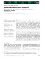
2. Methodologies
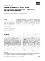
2.1. Local scour problem at downstream of
sluice and culvert
Maximum scour depth or equilibrium depth
(ds) is the most important parameter of scour
geometry, which is studied prevalently by
several methods. All of them considered that ds
is function of a) initial hydraulic conditions:
input discharge (Q), water depth at upstream
(Yu) and downstream (Yt); b) geometry of sluice
or culvert: open height of sluice gate (a); the
length of apron (L); the sharp of culvert: circle,
box; the length, slope of culvert, the height of
Journal of Water Resources & Environmental Engineering - No. 82 (12/2022)
87
culvert (d); c) the available of auxiliary devices:
wingwall;
blockage;
d)
bed
material
information: soil density (s), mean grain size
(d50), standard deviation (), type of soil:
cohesive and non-cohesive; e) gravity
acceleration (g), density of water () (Figure 1).
Besides, some dimensionless parameters are
often involved in building the equation of ds, i.e.
Froude number of the jet of water after sluice
gate (F): F V / gh with V is jet velocity;
densimetric
Froude
number
(Fd):
Fd V / s 1 gd50 ; discharge intensity
(DI): DI Q / g1/2 d 5/2 .
Note that the function will be different for
any combination of sluice outlet configuration.
2.2. Physical model
Physical model is considered as traditional
method, which are usually used to build
empirical equations to calculate maximum scour
depth and scour hole geometry (Emami, 2004;
Galán & González, 2020; Abt et al., 1985,
Abida & Townsend, 1991). However, physical
models also exposed several limitations
including
time-consuming
and
costly.
Especially, it is not flexible or easy to change
the dimension or to install auxiliary work as
well as the initial conditions, and boundary
conditions during experimenting. Besides, the
narrow range of physical conditions causes
limitations when applying these empirical
equations in case studies.
a)
b)
Figure 1. Schematic of sediment geometry
after: a) sluice and b) culvert
In general, maximum value ds after culvert is
analyzed and expressed as:
ds
d
Y Y
Y Y
u , t , Fd or s u , t , DI ; (1)
d
d
d d
d d
which is base for the experiment campaign.
Note that the function will be different for
any combination of culvert shape, culvert outlet
configuration and blockage at inlet.
While, this value after sluice gate is also
dimensional analyzed:
ds
L Y
(2)
, t , Fd
a
a a
88
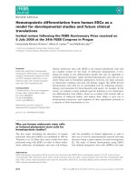
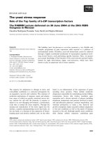
Figure 2. Scour hole after circle culvert
(Galán & González, 2020)
The scouring process downstream of an
apron is complex in nature owing to the abrupt
change of the flow characteristics on the
sediment bed with time (Dey & Sarkar, 2006).
When the bed shear stress exceeds the critical
bed shear stress, the scour initiated at
downstream edge of apron. Usually,
equilibrium time (ts) to get steady state of
scour hole is also firstly investigated. Then,
the dimension of scour geometry in empirical
tests are often studied as a function of tail
water depth (Yt); effect of wingwall; effect of
culvert sharp; effect of soil properties,
Journal of Water Resources & Environmental Engineering - No. 82 (12/2022)
(Figure 2) (Galán & González, 2020). On the
other hand, many researchers tried to build the
empirical equations in estimating the non
dimensionless value (ds/d) for culvert and
(ds/a) for sluice based on observed data. These
equations are efficient tools in predicting
scour depth after hydraulic constructions
when design these works. However, most of
them have limitation range of application due
to experimental conditions. Two subsections
2.2.1 and 2.2.2 presented some empirical
formula, analytical one taken from published
literatures.
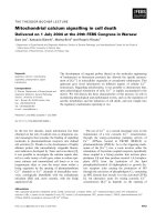
2.2.1. Culvert
Table 1. Empirical equations of scour depth after culvert
No
1
Investigations
Lim (1995)
2
Abt et al. (1983)
3
Ruff et al. (1984)
7.3-33.7
4
Emami
&
Schleiss. (2010)
7.5-14.5
0.9-1.3
5
Mendoza et al.
(1983)
N/A
Circle
6
Taha et al. (2020)
0.9-2.11
Box
7
Abida
&
Townsend (1991)
Fd
1.91-2.46
DI
Circle
0.4-3.0
(Yt/d)
0.22-7.34
(ds/D)
ds
0.57
0.4
0.4
3.67 Fd d 50 / d
d
ds
0.37
0.45
2.08 DI
d
ds
0.45
0; 0.25;
2.07 DI
D
0.45
0.15;
Y
a 0.6 t 1.8
1.05
ds
d
a ln Fd b;
d
b 1.23 Yt 2.25
d
ds
0.37
Without wingwall
2.08 DI
d
ds
0.36
With wingwall
2.04 DI
d
Y
1.25-1.75 d s
0.56Fd 0.45 t 1.05
d
d
Box
In seven investigations mentioned in the
Table 1, there is only the equation of Mendoza
et al., (1983) accounted for the influence of
wingwall on scour depth. Therefore, in order to
study the effect of dimension of this device or
ds
F 2
d
exp d
0.373 50
d
2.03
d
0.275
other kinds of auxiliary work on scour geometry
in more detail, numerical model should be used
(Le et al., 2022).
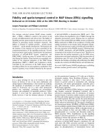
2.2.2. Sluice gate
Table 2. Equations of maximum scour depth after sluice gate
No
1
2
Number
of data
Chatterjee et al. 28
(1994)
Sarkar & Dey 38
(2005)
Investigations
ds/a
d50/a
F
0.91.4
2.278.16
0.020.22
0.020.44
1.025.46
2.374.87
ds
ds
0.775 Fd
a
ds
L
0.42Fd0.49
a
a
Journal of Water Resources & Environmental Engineering - No. 82 (12/2022)
0.36
1.08
Yt
a
89
No
3
4
Number
of data
Dey & Sarkar 205
(2006)
Investigations
Hoàng (2012)
ds/a
d50/a
F
ds
2.278.16
0.020.44
2.374.87
ds
L
Yt d50
2.59 Fd0.94
a
a
a a
m3 Am2 B m C 0; m ds / Yt ; and:
N/A
0.37
0.16
0.25
A 2 F 0.385Vk2 o 2
B 2 A 1.54 FVk 3
C 2 F 0.77Vk 0.385Vk2 o 1.385
Vk
ko
1/6
F 1/3 Yt / d50
;
Vk : non erosion velocity (m / s)
The equation of Hoàng (2012) in the Table 2
is the analytical formula, which was generated
from boundary layer and jet theory while other
are taken from empirical data.
In general, soil types used in almost
physical model are non-cohesive. Many tests
used only one soil property. Auxiliary devices
such as headwall, blockage, apron types like
rough or smooth are rarely studies. Besides,
due to the lack of quantity of data in many
works, the empirical equations extracted from
it may be less accurate (Aamir & Ahmad,
2019a). On the other hand, small-scale
laboratory experiments have errors caused by
scale effect. Because local scour involves
complex interactions between sediment, water
flow and structures, so it is impossible to
ensure all the similarities in a laboratory
experiment on scouring (Zhao, 2022).
2.3. Numerical model
Numerical methods have been increasingly
used in the study of scour around structures
because of their high efficiency and the quickly
growing capability of computers for large-scale
numerical simulations. Conducting threedimensional computational fluid dynamics
(CFD) simulations can provide a good
understanding of vortex structures, which are
responsible for scour. Therefore, 3D CFD
90
models solved Navier-Stokes equations by the
Volume of Fluid (VOF) method, which is based
on the conservation of two mass and
momentum, are often used to simulate this
problem. A numerous researchers simulated
scour hole geometry after culvert or sluice. A
number of well-known Computational Fluid
Dynamics (CFD) models including OpenFoam,
Ansys Fluent, Flow 3D, etc., has been widely
utilized in this field (Taha et al., 2020;
Elnikhely & Fathy, 2020; Yu et al., 2020; Török
et al., 2017). These numerical models based on
the coupling of the Volume Fluid Method and
Navier Stokes equations have played important
roles in simulating sediment scour issue due to
the help of state-of-the-art 3D CFD models. The
deformation of bed geometry can be
demonstrated by the sediment scour module.
This model can simulate the sediment transport
process, which includes settling, packing,
advection, bedload transport, entrainment, and
depositions for each species of soil material.
Due to the help of a state-of-the-art 3D CFD
model, the process of the bed deformation can
be performed clearly. So, geometry of scour
hole as well as sand mound can be overall
predicted. Two mathematical equation systems
presented in two subsections 2.4.1 and 2.4.2 are
usually solved.
Journal of Water Resources & Environmental Engineering - No. 82 (12/2022)
2.3.1. Navier-Stokes equations
In general, bedload and suspended transport are
used to describe the movement of sand particles in
fluid flow. In the mathematical model, the bed
boundary can be considered as a packed one if the
local scour occurred at that place. The
morphology of the packed boundary is estimated
based on the conservation of mass. This process
includes bedload transport, absorption, and
deposition. The suspended sediment is estimated
by sediment concentration and is considered a
constraint at each computational cell. For each soil
type, this term is estimated by the following
continuity equation:
Vf
uAx vAy wAz 0 (3)
t
x
y
z
where Vf is volume fraction; is fluid
density; u, v, and w are velocity components in
the x, y, and z directions, respectively; and Ax,
Ay, and Az are the area fractions.
Three momentum equations in the x, y, and z
directions are as follows:
u 1
u
u
u
1 p
vAy
wAx
Gx f x
uAx
t VF
x
y
z
x
v 1
t VF
v
v
v
1 p
vAy
wAx
Gy f y
uAx
x
y
z
y
(4)
w 1
w
w
w
1 p
vAy
wAx
Gz f z
uAx
t VF
x
y
z
z
Gx, Gy, and Gz are the body accelerations, and fx, fy, and fz are the viscous accelerations.
2.3.2. Sediment scour model
The sediment transport process is often
described by bedload transport and suspended
transport. Bedload transport illustrates the
motion of soil particles, such as rolling,
hopping, and sliding along the packed bed
surface due to the shear stress. Bedload
transport means the movement of sand particles
along the bed channel, regardless of whether
some of them become suspended movement.
The empirical formulas estimating bedload
transport applied in the 3D numerical model
were Meyer-Peter Muller, Nielsen, or Van Rijin
(Meyer & Müller, 1948; Van Rijn, 1984).
The critical Shields parameter θcr is used to
define the critical bed shear stress τcr, at which
sediment movement begins for both entrainment
and bedload transport, which is applied to the
horizontal bed.
cr
cr
(5)
gd50 s
The Soulsby–Whitehouse equation is used to
estimate the critical shear stress as follows:
0.3
cr
0.055 1 e 0.02 d*
1 1.2d*
(6)
1/3
g s / 1
d* d50
v
where s the kinematic viscosity of
the fluid.
The suspended sediment concentration is
calculated by solving the following equation:
C s
. C s .u s . K .C s
(7)
t
where Cs is the suspended sediment mass
concentration, which is defined as the
sediment mass per volume of fluid–sediment
mixture; K is the diffusivity; and us is the
sediment velocity.
However, due to the application of several
hypotheses of the numerical model in
simulating sediment transport such as non
cohesive soil or the influence of grid size on
Journal of Water Resources & Environmental Engineering - No. 82 (12/2022)
91
numerical result, the numerical approach also
exposed some limitations in estimating the
dimension of the scour hole. In all studies
using CFD model, the sediment particles are
assumed to be spherical instead of irregular
shapes. Considering random shapes of
sediment particles in CFD models is still
challenging.
Besides, bedload transport equations used in
the 3D CFD model are empirical ones, so
numerical result is mainly influenced by the
selected bedload equation in simulating.
Therefore, the numerical parameters should be
calibrated and validated by experimental data.
2.4. AI approaches
On the other hand, recently, researchers
have expressed keen interest in favor of
using soft-computing techniques to predict
the scour depth near various hydraulic
structures. Some Artificial Intelligence (AI)
approaches have been recently applied to
predict the maximum scour depth in
hydraulic structures (Najafzadeh, 2016;
Najafzadeh & Kargar, 2019).
Some artificial intelligence (AI) approaches
such as artificial neural networks (ANNs),
adaptive
neuro-fuzzy
inference
system
(ANFIS), genetic programming (GP), gene
expression programming (GEP), group method
of data handling (GMDH), and support vector
machine (SVM) have been applied to predict the
local scour depth at the outlet of culvert (e.g.,
Liriano & Day, 2001; Azamathulla & Haque,
2012; Najafzadeh, 2016) or sluice (Aamir &
Ahmad, 2019b; Najafzadeh & Kargar, 2019;
Galán & González, 2020; Najafzadeh & Lim,
2015; Eghbalzadeh et al., 2018; Karbasi &
Azamathulla, 2017). In the case of scour depth
prediction at the outlets, it should be noted that
a large number of studies conducted by AI
approaches were a suitable platform in order to
92
reach the scour depth prediction with
permissible level of accuracy rather than
empirical equations, (Liriano & Day, 2001;
Azamathulla & Haque, 2012; Najafzadeh &
Lim, 2015). Among mentioned AI models, GP,
GEP, and GMDH approaches have the
capability of describing a relationship among
input and output variables for different realms
of scouring problems.
Liriano and Day, (2001) showed that the
ANN can successfully predict the depth of scour
after culvert with a greater accuracy than
existing empirical formulae and over a wider
range of conditions. Aamir and Ahmad, (2019a)
proved that, empirical equation of Dey and
Sarkar, (2006) predicted scour depth after sluice
gate with statistical error analysis RMSE value
of 0.1 while ANN gave this value for both
training and testing 0.05.
However, AI approaches have not been
proposed to predict the location of the
maximum scour depth and other scour hole
geometries (Najafzadeh, 2016). Besides, the
accuracy level of predicted equilibrium scour
depth taken from this method highly depends on
the quantity and quality of databases, which is
usually the experimental data.
3. Conclusion
This paper reviewed three methods to
predict sediment scour after sluice and culvert.
Physical model is considered as a traditional
method and still widely used because of its
accuracy. It provided database or evidence to
other methods. However, it exposed some
limitations such as: narrow range of initial
conditions in application, inflexible in
changing facility, expensive budget and timeconsuming. The empirical equations taken
from experiment data are efficient and quick
tools in predicting the maximum scour depth.
Journal of Water Resources & Environmental Engineering - No. 82 (12/2022)
But this result is less accurate than that
obtained by AI approach, which is an up-todate method in predicting equilibrium scour
depth. However, the AI result strongly
depends on the quantity and quality of
database and this method cannot delineate the
performance of scour hole. Besides, 3D CFD
method performs well the process of sediment
transport in the computational domain. It is
quite easy and flexible to change initial
conditions, boundary condition or substitute
auxiliary work. However, both experimental
and numerical studies of scour have been
mainly focused on inviscid, loose sand.
Therefore, based on sediment scour problems
and available data as well as the pros and con
and application range of each method, the
researchers can decide which is the sufficient
tool to solve scouring issue.
References
Aamir, M., & Ahmad, Z. (2016). Review of
literature on local scour under plane turbulent
wall jets. Physics of Fluids,
/>
28(10).
Aamir, M., & Ahmad, Z. (2019a). Estimation of
maximum scour depth downstream of an apron
under submerged wall jets. Journal of
Hydroinformatics,
21(4),
523–540.
/>Aamir, M., & Ahmad, Z. (2019b). Hydraulics of
submerged jets causing scour downstream of a
rough rigid apron Hydraulics of submerged
jets causing scour downstream of a rough rigid
apron. September.
Abt, S. R., Donnell, C. A., Ruff, J. F., &
Doehring, F. K. (1985). Culvert Slope and
Shape Effects on Outlet Scour. Transportation
Research Record, 2, 24–30.
Abt, S. R., Ruff, J. F., & Mendoza, C. (1983).
Mound formation at culvert outlet. JAWRA
Journal of the American Water Resources
Association, 19(4), 571–576. />10.1111/J.1752-1688.1983.TB02772.X
Azamathulla, H. M., & Haque, A. A. M. (2012).
Prediction of scour depth at culvert outlets
using
Gene-Expression
Programming.
International Journal of Innovative Computing,
Information and Control, 8(7 B), 5045–5054.
Chatterjee, S. S., Ghosh, S. N., & Chatterjee, M.
(1994). Local Scour due to Submerged
Horizontal Jet. Journal of Hydraulic
Engineering,
120(8),
973–992.
/>Dey, S., & Sarkar, A. (2006). Scour Downstream
of an Apron Due to Submerged Horizontal
Jets. Journal of Hydraulic Engineering, 132(3),
246–257. />Eghbalzadeh, A., Hayati, M., Rezaei, A., & Javan,
M. (2018). Prediction of equilibrium scour
depth in uniform non-cohesive sediments
downstream of an apron using computational
intelligence.
European
Journal
of
Environmental and Civil Engineering, 22(1),
28–41. 19648189
.2016.1179677
Elnikhely, E. A., & Fathy, I. (2020). Prediction of
scour downstream of triangular labyrinth
weirs. Alexandria Engineering Journal, 59(2),
1037–1047.
/>Galán, Á., & González, J. (2020). Effects of shape,
inlet blockage and wing walls on local scour at
the outlet of non-submerged culverts:
undermining
of
the
embankment.
Environmental
Earth
Sciences,
79(1).
/>
Journal of Water Resources & Environmental Engineering - No. 82 (12/2022)
93
Abida, H & Townsend, R.D (1991). Local scour
M.
Neurofuzzy-Based
(2016).
downstream of box culvert outlets. Journal of
GMDH-PSO to Predict Maximum Scour Depth
Irrigation and Drainage Engineering, 117(3),
at Equilibrium at Culvert Outlets. Journal of
425–440.
Pipeline Systems Engineering and Practice,
Hồng, T. A. (2012). Thủy lực cơng trình. NXB
Nông nghiệp.
7(1),
06015001.
/>
(asce)ps.1949-1204.0000204
Karbasi, M., & Azamathulla, H. M. (2017).
Najafzadeh, M., & Kargar, A. R. (2019). Gene-
Prediction of scour caused by 2D horizontal
Expression
jets using soft computing techniques. Ain
Polynomial Regression, and Model Tree to
Shams Engineering Journal, 8(4), 559–570.
Evaluate Local Scour Depth at Culvert Outlets.
/>
Journal of Pipeline Systems Engineering and
Le, H. T. T., Nguyen, C. Van, & Le, D.-H. (2022).
Numerical study of sediment scour at meander
flume outlet of boxed culvert diversion work.
Plos
One,
17(9),
e0275347.
/>Lim,
S.Y. (1995). Scour below unsubmerged
culvert outlets. Proc. Instn Civ. Engrs Wat.,
Marit. &Energy, 136–149.
Liriano, S. L., & Day, R. A. (2001). Prediction of
scour depth at culvert outlets using neural
networks. Journal of Hydroinformatics, 3(4),
Programming,
Practice,
Evolutionary
10(3),
04019013.
/>Najafzadeh, M., & Lim, S. Y. (2015). Application
of improved neuro-fuzzy GMDH to predict
scour depth at sluice gates. Earth Science
Informatics,
8(1),
187–196.
/>Ruff, J, Mendoza, C, Shaikh, A. K. (1984). Scour
at culvert outlets in multibed materials.
Transportation Research Record, 948, 55–62.
231–238.
/>Mendoza, C., Abt, S. R., & Ruff, J. F. (1983).
Sarkar, A., & Dey, S. (2005). Scour downstream
of aprons caused by sluices. Proceedings of the
Headwall Influence on Scour at Culvert
Institution
Outlets. Journal of Hydraulic Engineering.
Management,
Hydraulic Engineering, 109(7), 1056–1060.
/>
Civil
Engineers:
158(2),
Water
55–64.
downstream of diversion tunnels concrete
9429(1983)109:7(1056) (1983)
Mendoza, C. (1984). Unified Culvert Scour
Determination.
of
Soleyman Emami. (2004). Erosion protection
/>
Hydraulic
Engineering,
prisms – Design criteria based on a systematic
physical
model
study.
Laboratoire
110(10), 1475–1479. />
Constructions
(ASCE)0733-9429(1984)110
Polytechnique Fédérale de Lausanne.
Hydrauliques
de
Ecole
(1948).
Emami, S and Schleiss, A.J (2010). Prediction of
transport.
localized scour hole on natural mobile bed at
Proceedings of the 2nd Meeting of the
culvert outlets. JInternational Conference on
International
Scour and Erosion 2010 (ICSE-5) Scour and
Meyer-Peter,
E.
Formulas
and
for
Müller,
R.
bed-load
Association
Structures Research, 39–64.
94
Najafzadeh,
for
Hydraulic
Erosion, 2010(0), 241–250.
Journal of Water Resources & Environmental Engineering - No. 82 (12/2022)
Taha, N., El-Feky, M. M., El-Saiad, A. A., &
Fathy, I. (2020). Numerical investigation of
scour characteristics downstream of blocked
culverts. Alexandria Engineering Journal,
59(5), 3503–3513. />j.aej.2020.05.032
Török, G. T., Baranya, S., & Rüther, N. (2017).
3D CFD modeling of local scouring, bed
armoring and sediment deposition. Water
(Switzerland), 9(1). />w9010056
Van Rijn, L. C. (1984). Sediment Transport, Part
I: Bed Load Transport. Journal of Hydraulic
Engineering,
110(10),
1431–1456.
/>Yu, P., Hu, R., Yang, J., & Liu, H. (2020).
Numerical investigation of local scour around
USAF with different hydraulic conditions
under currents and waves. Ocean Engineering,
213(238), 107696. />j.oceaneng.2020.107696
Zhao, M. (2022). A Review on Recent
Development of Numerical Modelling of Local
Scour around Hydraulic and Marine
Structures. Journal of Marine Science and
Engineering,
10(8).
/>
Journal of Water Resources & Environmental Engineering - No. 82 (12/2022)
95