Verilog HDL
Bạn đang xem bản rút gọn của tài liệu. Xem và tải ngay bản đầy đủ của tài liệu tại đây (269.55 KB, 80 trang )
Page 479 Black
October 14, 1997
479
VERILOG HDL 11
In this chapter we look at the Verilog hardware description language. Gateway
Design Automation developed Verilog as a simulation language. The use of the
Verilog-XL simulator is discussed in more detail in Chapter 13. Cadence purchased
Gateway in 1989 and, after some study, placed the Verilog language in the public
domain. Open Verilog International (OVI) was created to develop the Verilog lan-
guage as an IEEE standard. The definitive reference guide to the Verilog language is
now the Verilog LRM, IEEE Std 1364-1995 [1995].
1
This does not mean that all
Verilog simulators and tools adhere strictly to the IEEE Standard—we must abide by
the reference manual for the software we are using. Verilog is a fairly simple lan-
guage to learn, especially if you are familiar with the C programming language. In
this chapter we shall concentrate on the features of Verilog applied to high-level
design entry and synthesis for ASICs.
1
Some of the material in this chapter is reprinted with permission from IEEE Std 1364-
1995, © Copyright 1995 IEEE. All rights reserved.
11.1 A Counter
11.2 Basics of the Verilog Language
11.3 Operators
11.4 Hierarchy
11.5 Procedures and Assignments
11.6 Timing Controls and Delay
11.7 Tasks and Functions
11.8 Control Statements
11.9 Logic-Gate Modeling
11.10 Modeling Delay
11.11 Altering Parameters
11.12 A Viterbi Decoder
11.13 Other Verilog Features
11.14 Summary
11.15 Problems
11.16 Bibliography
11.17 References
11
Page 480 Black
October 14, 1997
480 CHAPTER 11 VERILOG HDL
11.1 A Counter
The following Verilog code models a “black box” that contains a 50MHz clock
(period 20ns), counts from 0 to 7, resets, and then begins counting at 0 again:
`timescale 1ns/1ns //1
module counter; //2
reg clock; // Declare reg data type for the clock. //3
integer count; // Declare integer data type for the count. //4
initial // Initialize things - this executes once at the start. //5
begin //6
clock = 0; count = 0; // Initialize signals. //7
#340 $finish; // Finish after 340 time ticks. //8
end //9
/* An always statement to generate the clock, only one statement
follows the always so we don't need a begin and an end. */ //10
always //11
#10 clock = ~ clock; // Delay is set to half the clock cycle. //12
/* An always statement to do the counting, runs at the same time
(concurrently) as the other always statement. */ //13
always //14
begin //15
// Wait here until the clock goes from 1 to 0. //16
@ (negedge clock); //17
// Now handle the counting. //18
if (count == 7) //19
count = 0; //20
else //21
count = count + 1; //22
$display("time = ",$time," count = ", count); //23
end //24
endmodule //25
Verilog keywords (reserved words that are part of the Verilog language) are
shown in bold type in the code listings (but not in the text). References in this chap-
ter such as [Verilog LRM 1.1] refer you to the IEEE Verilog LRM.
The following output is from the Cadence Verilog-XL simulator. This example
includes the system input so you can see how the tool is run and when it is finished.
Some of the banner information is omitted in the listing that follows to save space
(we can use “quiet” mode using a '-q' flag, but then the version and other useful
information is also suppressed):
> verilog counter.v
VERILOG-XL 2.2.1 Apr 17, 1996 11:48:18
Banner information omitted here
Compiling source file "counter.v"
Highest level modules:
Page 481 Black
October 14, 1997
11.1 A COUNTER 481
counter
time = 20 count = 1
time = 40 count = 2
( 12 lines omitted )
time = 300 count = 7
time = 320 count = 0
L10 "counter.v": $finish at simulation time 340
223 simulation events
CPU time: 0.6 secs to compile + 0.2 secs to link + 0.0 secs in
simulation
End of VERILOG-XL 2.2.1 Apr 17, 1996 11:48:20
>
Here is the output of the VeriWell simulator from the console window (future
examples do not show all of the compiler output— just the model output):
Veriwell -k VeriWell.key -l VeriWell.log -s :counter.v
banner information omitted
Memory Available: 0
Entering Phase I
Compiling source file : :counter.v
The size of this model is [1%, 1%] of the capacity of the free version
Entering Phase II
Entering Phase III
No errors in compilation
Top-level modules:
counter
C1> .
time = 20 count = 1
time = 40 count = 2
( 12 lines omitted )
time = 300 count = 7
time = 320 count = 0
Exiting VeriWell for Macintosh at time 340
0 Errors, 0 Warnings, Memory Used: 29468
Compile time = 0.6, Load time = 0.7, Simulation time = 4.7
Normal exit
Thank you for using VeriWell for Macintosh
Page 482 Black
October 14, 1997
482 CHAPTER 11 VERILOG HDL
11.2 Basics of the Verilog Language
A Verilog identifier, including the names of variables, may contain any sequence of
letters, digits, a dollar sign '$', and the underscore '_' symbol. The first character
of an identifier must be a letter or underscore; it cannot be a dollar sign '$', for
example. We cannot use characters such as '-' (hyphen), brackets, or '#' (for
active-low signals) in Verilog names (escaped identifiers are an exception). The fol-
lowing is a shorthand way of saying the same thing:
identifier ::= simple_identifier | escaped_identifier
simple_identifier ::= [a-zA-Z][a-zA-Z_$]
escaped_identifier ::=
\ {Any_ASCII_character_except_white_space} white_space
white_space ::= space | tab | newline
If we think of '::=' as an equal sign, then the preceding “equation” defines
the syntax of an identifier. Usually we use the Backus–Naur form (BNF) to write
these equations. We also use the BNF to describe the syntax of VHDL. There is an
explanation of the BNF in Appendix A. Verilog syntax definitions are given in
Appendix B. In Verilog all names, including keywords and identifiers, are case-
sensitive. Special commands for the simulator (a system task or a system function)
begin with a dollar sign '$' [Verilog LRM 2.7]. Here are some examples of
Verilog identifiers:
module identifiers; //1
/* Multiline comments in Verilog //2
look like C comments and // is OK in here. */ //3
// Single-line comment in Verilog. //4
reg legal_identifier,two__underscores; //5
reg _OK,OK_,OK_$,OK_123,CASE_SENSITIVE, case_sensitive; //6
reg \/clock ,\a*b ; // Add white_space after escaped identifier. //7
//reg $_BAD,123_BAD; // Bad names even if we declare them! //8
initial begin //9
legal_identifier = 0; // Embedded underscores are OK, //10
two__underscores = 0; // even two underscores in a row. //11
_OK = 0; // Identifiers can start with underscore //12
OK_ = 0; // and end with underscore. //13
OK$ = 0; // $ sign is OK, but beware foreign keyboards.//14
OK_123 =0; // Embedded digits are OK. //15
CASE_SENSITIVE = 0; // Verilog is case-sensitive. //16
case_sensitive = 1; //17
\/clock = 0; // Escaped identifier with \ breaks rules, //18
\a*b = 0; // but be careful! watch the spaces. //19
$display("Variable CASE_SENSITIVE= %d",CASE_SENSITIVE); //20
$display("Variable case_sensitive= %d",case_sensitive); //21
$display("Variable \/clock = %d",\/clock ); //22
$display("Variable \\a*b = %d",\a*b ); //23
Page 483 Black
October 14, 1997
11.2 BASICS OF THE VERILOG LANGUAGE 483
end //24
endmodule //25
The following is the output from this model (future examples in this chapter list
the simulator output directly after the Verilog code).
Variable CASE_SENSITIVE= 0
Variable case_sensitive= 1
Variable /clock = 0
Variable \a*b = 0
11.2.1 Verilog Logic Values
Verilog has a predefined logic-value system or value set [Verilog LRM 3.1] that uses
four logic values: '0', '1', 'x', and 'z' (lowercase 'x' and lowercase 'z'). The
value 'x' represents an uninitialized or an unknown logic value—an unknown value
is either '1', '0', 'z', or a value that is in a state of change. The logic value 'z'
represents a high-impedance value, which is usually treated as an 'x' value. Verilog
uses a more complicated internal logic-value system in order to resolve conflicts
between different drivers on the same node. This hidden logic-value system is useful
for switch-level simulation, but for most ASIC simulation and synthesis purposes we
do not need to worry about the internal logic-value system.
11.2.2 Verilog Data Types
There are several data types in Verilog—all except one need to be declared before
we can use them. The two main data types are nets and registers [Verilog LRM 3.2].
Nets are further divided into several net types. The most common and important net
types are: wire and tri (which are identical); supply1 and supply0 (which are equiv-
alent to the positive and negative power supplies respectively). The wire data type
(which we shall refer to as just wire from now on) is analogous to a wire in an
ASIC. A wire cannot store or hold a value. A wire must be continuously driven by
an assignment statement (see Section 11.5). The default initial value for a wire is
'z'. There are also integer, time, event, and real data types.
module declarations_1; //1
wire pwr_good, pwr_on, pwr_stable; // Explicitly declare wires. //2
integer i; // 32-bit, signed (2's complement) //3
time t; // 64-bit, unsigned, behaves like a 64-bit reg //4
event e; // Declare an event data type. //5
real r; // Real data type of implementation defined size. //6
// assign statement continuously drives a wire: //7
assign pwr_stable = 1'b1; assign pwr_on = 1; // 1 or 1'b1 //8
assign pwr_good = pwr_on & pwr_stable; //9
initial begin //10
i = 123.456; // There must be a digit on either side //11
r = 123456e-3; // of the decimal point if it is present. //12
Page 484 Black
October 14, 1997
484 CHAPTER 11 VERILOG HDL
t = 123456e-3; // Time is rounded to 1 second by default. //13
$display("i=%0g",i," t=%6.2f",t," r=%f",r); //14
#2 $display("TIME=%0d",$time," ON=",pwr_on, //15
" STABLE=",pwr_stable," GOOD=",pwr_good); //16
$finish; end //17
endmodule //18
i=123 t=123.00 r=123.456000
TIME=2 ON=1 STABLE=1 GOOD=1
A register data type is declared using the keyword reg and is comparable to a
variable in a programming language. On the LHS of an assignment a register data
type (which we shall refer to as just reg from now on) is updated immediately and
holds its value until changed again. The default initial value for a reg is 'x'. We can
transfer information directly from a wire to a reg as shown in the following code:
module declarations_2; //1
reg Q, Clk; wire D; //2
// drive the wire (D) //3
assign D = 1; //4
// At +ve clock edge assign the value of wire D to the reg Q: //5
always @(posedge Clk) Q = D; //6
initial Clk = 0; always #10 Clk = ~ Clk; //7
initial begin #50; $finish; end //8
always begin //9
$display("T=%2g", $time," D=",D," Clk=",Clk," Q=",Q); #10; end //10
endmodule //11
T= 0 D=z Clk=0 Q=x
T=10 D=1 Clk=1 Q=x
T=20 D=1 Clk=0 Q=1
T=30 D=1 Clk=1 Q=1
T=40 D=1 Clk=0 Q=1
We shall discuss assignment statements in Section 11.5. For now, it is important
to recognize that a reg is not always equivalent to a hardware register, flip-flop, or
latch. For example, the following code describes purely combinational logic:
module declarations_3; //1
reg a,b,c,d,e; //2
initial begin //3
#10; a = 0;b = 0;c = 0;d = 0; #10; a = 0;b = 1;c = 1;d = 0; //4
#10; a = 0;b = 0;c = 1;d = 1; #10; $stop; //5
end //6
always begin //7
@(a or b or c or d) e = (a|b)&(c|d); //8
$display("T=%0g",$time," e=",e); //9
end //10
endmodule //11
T=10 e=0
Page 485 Black
October 14, 1997
11.2 BASICS OF THE VERILOG LANGUAGE 485
T=20 e=1
T=30 e=0
A single-bit wire or reg is a scalar (the default). We may also declare a wire
or reg as a vector with a range of bits [Verilog LRM 3.3]. In some situations we
may use implicit declaration for a scalar wire; it is the only data type we do not
always need to declare. We must use explicit declaration for a vector wire or any
reg. We may access (or expand) the range of bits in a vector one at a time, using a
bit-select, or as a contiguous subgroup of bits (a continuous sequence of numbers—
like a straight in poker) using a part-select [Verilog LRM 4.2]. The following code
shows some examples:
module declarations_4; //1
wire Data; // A scalar net of type wire. //2
wire [31:0] ABus, DBus; // Two 32-bit-wide vector wires: //3
// DBus[31] = leftmost = most-significant bit = msb //4
// DBus[0] = rightmost = least-significant bit = lsb //5
// Notice the size declaration precedes the names. //6
// wire [31:0] TheBus, [15:0] BigBus; // Illegal. //7
reg [3:0] vector; // A 4-bit vector register. //8
reg [4:7] nibble; // msb index < lsb index is OK. //9
integer i; //10
initial begin //11
i = 1; //12
vector = 'b1010; // Vector without an index. //13
nibble = vector; // This is OK too. //14
#1; $display("T=%0g",$time," vector=", vector," nibble=", nibble); //15
#2; $display("T=%0g",$time," Bus=%b",DBus[15:0]); //16
end //17
assign DBus [1] = 1; // This is a bit-select. //18
assign DBus [3:0] = 'b1111; // This is a part-select. //19
// assign DBus [0:3] = 'b1111; // Illegal : wrong direction. //20
endmodule //21
T=1 vector=10 nibble=10
T=3 Bus=zzzzzzzzzzzz1111
There are no multidimensional arrays in Verilog, but we may declare a memory
data type as an array of registers [Verilog LRM 3.8]:
module declarations_5; //1
reg [31:0] VideoRam [7:0]; // An 8-word by 32-bit wide memory. //2
initial begin //3
VideoRam[1] = 'bxz; // Must specify an index for a memory. //4
VideoRam[2] = 1; //5
VideoRam[7] = VideoRam[VideoRam[2]]; // Need 2 clock cycles for this. //6
VideoRam[8] = 1; // Careful! the compiler won't complain! //7
// Verify what we entered: //8
Page 486 Black
October 14, 1997
486 CHAPTER 11 VERILOG HDL
$display("VideoRam[0] is %b",VideoRam[0]); //9
$display("VideoRam[1] is %b",VideoRam[1]); //10
$display("VideoRam[2] is %b",VideoRam[2]); //11
$display("VideoRam[7] is %b",VideoRam[7]); //12
end //13
endmodule //14
VideoRam[0] is xxxxxxxxxxxxxxxxxxxxxxxxxxxxxxxx
VideoRam[1] is xxxxxxxxxxxxxxxxxxxxxxxxxxxxxxxz
VideoRam[2] is 00000000000000000000000000000001
VideoRam[7] is xxxxxxxxxxxxxxxxxxxxxxxxxxxxxxxz
We may also declare an integer array or time array in the same way as an
array of reg, but there are no real arrays [Verilog LRM 3.9]:
module declarations_6; //1
integer Number [1:100]; // Notice that size follows name //2
time Time_Log [1:1000]; // - as in array of reg //3
// real Illegal [1:10]; // ***no real arrays*** //4
endmodule //5
11.2.3 Other Wire Types
There are the following other Verilog wire types (rarely used in ASIC design)
[Verilog LRM 3.7.2]:
• wand, wor, triand, and trior model wired logic. Wiring, or dotting, the
outputs of two gates generates a logic function (in emitter-coupled logic,
ECL, or in an EPROM, for example). This is one area in which the logic val-
ues 'z' and 'x' are treated differently.
• tri0 and tri1 model resistive connections to VSS or VDD.
• trireg is like a wire but associates some capacitance with the net, so it can
model charge storage.
There are also other keywords that may appear in declarations:
• scalared and vectored are properties of vectors [Verilog LRM 3.3.2].
• small, medium, and large model the charge strength of trireg connections
[Verilog LRM 7].
11.2.4 Numbers
Constant numbers are integer or real constants [Verilog LRM 2.5]. Integer
constants are written as
width'radix value
where width and radix are optional. The radix (or base) indicates the type of num-
ber: decimal (d or D), hex (h or H), octal (o or O), or binary (b or B). A number may
be sized or unsized. The length of an unsized number is implementation dependent.
Page 487 Black
October 14, 1997
11.2 BASICS OF THE VERILOG LANGUAGE 487
We can use '1' and '0' as numbers since they cannot be identifiers, but we must
write 1'bx and 1'bz for 'x' and 'z'. A number may be declared as a parameter
[Verilog LRM 3.10]. A parameter assignment belongs inside a module declaration
and has local scope. Real constants are written using decimal (100.0) or scientific
notation (1e2) and follow IEEE Std 754-1985 for double-precision floating-point
numbers. Reals are rounded to the nearest integer, ties (numbers that end in .5)
round away from zero [Verilog LRM 3.9.2], but not all implementations follow this
rule (the output from the following code is from VeriWell, which rounds ties toward
zero for negative integers).
module constants; //1
parameter H12_UNSIZED = 'h 12; // unsized hex 12 = decimal 18 //2
parameter H12_SIZED = 6'h 12; // sized hex 12 = decimal 18 //3
// Notice that a space between base and value is OK //4
/* ‘’ (single apostrophes) are not the same as the ' character */ //5
parameter D42 = 8'B0010_1010; // bin 101010 = dec 42 //6
// we can use underscores to increase readability. //7
parameter D123 = 123; // unsized decimal (default) //8
parameter D63 = 8'o 77; // sized octal, decimal 63 //9
// parameter ILLEGAL = 1'o9; // no 9's in octal numbers! //10
/* A = 'hx and B = 'ox assume a 32 bit width */ //11
parameter A = 'h x, B = 'o x, C = 8'b x, D = 'h z, E = 16'h ????; //12
// we can use ? instead of z, same as E = 16'h zzzz //13
// note automatic extension to 16 bits //14
reg [3:0] B0011,Bxxx1,Bzzz1; real R1,R2,R3; integer I1,I3,I_3; //15
parameter BXZ = 8'b1x0x1z0z; //16
initial begin //17
B0011 = 4'b11; Bxxx1 = 4'bx1; Bzzz1 = 4'bz1; // left padded //18
R1 = 0.1e1; R2 = 2.0; R3 = 30E-01; // real numbers //19
I1 = 1.1; I3 = 2.5; I_3 = -2.5; // IEEE rounds away from 0 //20
end //21
initial begin #1; //22
$display //23
("H12_UNSIZED, H12_SIZED (hex) = %h, %h",H12_UNSIZED, H12_SIZED); //24
$display("D42 (bin) = %b",D42," (dec) = %d",D42); //25
$display("D123 (hex) = %h",D123," (dec) = %d",D123); //26
$display("D63 (oct) = %o",D63); //27
$display("A (hex) = %h",A," B (hex) = %h",B); //28
$display("C (hex) = %h",C," D (hex) = %h",D," E (hex) = %h",E); //29
$display("BXZ (bin) = %b",BXZ," (hex) = %h",BXZ); //30
$display("B0011, Bxxx1, Bzzz1 (bin) = %b, %b, %b",B0011,Bxxx1,Bzzz1);//31
$display("R1, R2, R3 (e, f, g) = %e, %f, %g", R1, R2, R3); //32
$display("I1, I3, I_3 (d) = %d, %d, %d", I1, I3, I_3); //33
end //34
endmodule //35
H12_UNSIZED, H12_SIZED (hex) = 00000012, 12
D42 (bin) = 00101010 (dec) = 42
D123 (hex) = 0000007b (dec) = 123
Page 488 Black
October 14, 1997
488 CHAPTER 11 VERILOG HDL
D63 (oct) = 077
A (hex) = xxxxxxxx B (hex) = xxxxxxxx
C (hex) = xx D (hex) = zzzzzzzz E (hex) = zzzz
BXZ (bin) = 1x0x1z0z (hex) = XZ
B0011, Bxxx1, Bzzz1 (bin) = 0011, xxx1, zzz1
R1, R2, R3 (e, f, g) = 1.000000e+00, 2.000000, 3
I1, I3, I_3 (d) = 1, 3, -2
11.2.5 Negative Numbers
Integer numbers are signed (two’s complement) or unsigned. The following
example illustrates the handling of negative constants [Verilog LRM 3.2.2, 4.1.3]:
module negative_numbers; //1
parameter PA = -12, PB = -'d12, PC = -32'd12, PD = -4'd12; //2
integer IA , IB , IC , ID ; reg [31:0] RA , RB , RC , RD ; //3
initial begin #1; //4
IA = -12; IB = -'d12; IC = -32'd12; ID = -4'd12; //5
RA = -12; RB = -'d12; RC = -32'd12; RD = -4'd12; #1; //6
$display(" parameter integer reg[31:0]"); //7
$display ("-12 =",PA,IA,,,RA); //8
$displayh(" ",,,,PA,,,,IA,,,,,RA); //9
$display ("-'d12 =",,PB,IB,,,RB); //10
$displayh(" ",,,,PB,,,,IB,,,,,RB); //11
$display ("-32'd12 =",,PC,IC,,,RC); //12
$displayh(" ",,,,PC,,,,IC,,,,,RC); //13
$display ("-4'd12 =",,,,,,,,,,PD,ID,,,RD); //14
$displayh(" ",,,,,,,,,,,PD,,,,ID,,,,,RD); //15
end //16
endmodule //17
parameter integer reg[31:0]
-12 = -12 -12 4294967284
fffffff4 fffffff4 fffffff4
-'d12 = 4294967284 -12 4294967284
fffffff4 fffffff4 fffffff4
-32'd12 = 4294967284 -12 4294967284
fffffff4 fffffff4 fffffff4
-4'd12 = 4 -12 4294967284
4 fffffff4 fffffff4
Verilog only “keeps track” of the sign of a negative constant if it is (1) assigned
to an integer or (2) assigned to a parameter without using a base (essentially the
same thing). In other cases (even though the bit representations may be identical to
the signed number—hex fffffff4 in the previous example), a negative constant is
treated as an unsigned number. Once Verilog “loses” the sign, keeping track of
signed numbers becomes your responsibility.
Page 489 Black
October 14, 1997
11.2 BASICS OF THE VERILOG LANGUAGE 489
11.2.6 Strings
The code listings in this book use Courier font. The ISO/ANSI standard for the
ASCII code defines the characters, but not the appearance of the graphic symbol in
any particular font. The confusing characters are the quote and accent characters:
module characters; /* //1
" is ASCII 34 (hex 22), double quote //2
' is ASCII 39 (hex 27), tick or apostrophe //3
/ is ASCII 47 (hex 2F), forward slash //4
\ is ASCII 92 (hex 5C), back slash //5
` is ASCII 96 (hex 60), accent grave //6
| is ASCII 124 (hex 7C), vertical bar //7
no standards for the graphic symbols for codes above 128 //8
´ is 171 (hex AB), accent acute in almost all fonts //9
“ is 210 (hex D2), open double quote, like 66 (some fonts) //10
” is 211 (hex D3), close double quote, like 99 (some fonts) //11
‘ is 212 (hex D4), open single quote, like 6 (some fonts) //12
’ is 213 (hex D5), close single quote, like 9 (some fonts) //13
*/ endmodule //14
Here is an example showing the use of string constants [Verilog LRM 2.6]:
module text; //1
parameter A_String = "abc"; // string constant, must be on one line //2
parameter Say = "Say \"Hey!\""; //3
// use escape quote \" for an embedded quote //4
parameter Tab = "\t"; // tab character //5
parameter NewLine = "\n"; // newline character //6
parameter BackSlash = "\\"; // back slash //7
parameter Tick = "\047"; // ASCII code for tick in octal //8
// parameter Illegal = "\500"; // illegal - no such ASCII code //9
initial begin //10
$display("A_String(str) = %s ",A_String," (hex) = %h ",A_String); //11
$display("Say = %s ",Say," Say \"Hey!\""); //12
$display("NewLine(str) = %s ",NewLine," (hex) = %h ",NewLine); //13
$display("\\(str) = %s ",BackSlash," (hex) = %h ",BackSlash); //14
$display("Tab(str) = %s ",Tab," (hex) = %h ",Tab,"1 newline "); //15
$display("\n"); //16
$display("Tick(str) = %s ",Tick," (hex) = %h ",Tick); //17
#1.23; $display("Time is %t", $time); //18
end //19
endmodule //20
A_String(str) = abc (hex) = 616263
Say = Say \"Hey!\" Say "Hey!"
NewLine(str) = \n (hex) = 0a
\(str) = \\ (hex) = 5c
Page 490 Black
October 14, 1997
490 CHAPTER 11 VERILOG HDL
Tab(str) = \t (hex) = 09 1 newline
Tick(str) = ' (hex) = 27
Time is 1
Instead of parameters you may use a define directive that is a compiler
directive, and not a statement [Verilog LRM 16]. The define directive has global
scope:
module define; //1
`define G_BUSWIDTH 32 // bus width parameter (G_ for global) //2
/* Note: there is no semicolon at end of a compiler directive. The
character ` is ASCII 96 (hex 60), accent grave, it slopes down from
left to right. It is not the tick or apostrophe character ' (ASCII 39
or hex 27)*/ //3
wire [`G_BUSWIDTH:0]MyBus; // 32-bit bus //4
endmodule //5
11.3 Operators
An expression uses any of the three types of operators: unary operators, binary oper-
ators, and a single ternary operator [Verilog LRM 4.1]. The Verilog operators are
similar to those in the C programming language—except there is no
autoincrement (++) or autodecrement ( ) in Verilog. Table 11.1 shows the opera-
tors in their (increasing) order of precedence and Table 11.2 shows the unary opera-
tors. Here is an example that illustrates the use of the Verilog operators:
module operators; //1
parameter A10xz = {1'b1,1'b0,1'bx,1'bz}; // concatenation //2
parameter A01010101 = {4{2'b01}}; // replication //3
// arithmetic operators: +, -, *, /, and modulus % //4
parameter A1 = (3+2) %2; // result of % takes sign of argument #1 //5
// logical shift operators: << (left), >> (right) //6
parameter A2 = 4 >> 1; parameter A4 = 1 << 2; // zero fill //7
// relational operators: <, <=, >, >= //8
initial if (1 > 2) $stop; //9
// logical operators: ! (negation), && (and), || (or) //10
parameter B0 = !12; parameter B1 = 1 && 2; //11
reg [2:0] A00x; initial begin A00x = 'b111; A00x = !2'bx1; end //12
parameter C1 = 1 || (1/0); /* this may or may not cause an //13
error: the short-circuit behavior of && and || is undefined. An //14
evaluation including && or || may stop when an expression is known //15
to be true or false */ //16
// == (logical equality), != (logical inequality) //17
Page 491 Black
October 14, 1997
11.3 OPERATORS 491
parameter Ax = (1==1'bx); parameter Bx = (1'bx!=1'bz); //18
parameter D0 = (1==0); parameter D1 = (1==1); //19
// === case equality, !== (case inequality) //20
// case operators only return true or false //21
parameter E0 = (1===1'bx); parameter E1 = 4'b01xz === 4'b01xz; //22
parameter F1 = (4'bxxxx === 4'bxxxx); //23
TABLE 11.1 Verilog operators (in increasing order of precedence).
?: (conditional) a ternary operator, a special form of <expression>
|| (logical or)
&& (logical and)
| (bitwise or) ~| (bitwise nor)
^ (bitwise xor) ^~ ~^ (bitwise xnor, equivalence)
& (bitwise and) ~& (bitwise nand)
== (logical equality) != (logical inequality) === (case equality) !== (case inequality)
< (less than) <= (less than or equal) > (greater than) >= (greater than or equal)
<< (shift left) >> (shift right)
+ (addition) - (subtraction)
* (multiply) / (divide) % (modulus)
Unary operators: ! ~ & ~& | ~| ^ ~^ ^~ + -
TABLE 11.2 Verilog unary operators.
Operator Name Examples
! logical negation !123 is 'b0
~ bitwise unary negation ~1'b10xz is 1'b01xx
& unary reduction and & 4'b1111 is 1'b1, & 2'bx1 is 1'bx, & 2'bz1 is 1'bx
~& unary reduction nand ~& 4'b1111 is 1'b0, ~& 2'bx1 is 1'bx
| unary reduction or
~| unary reduction nor
^ unary reduction xor
~^ ^~ unary reduction xnor
+ unary plus +2'bxz is +2'bxz
- unary minus -2'bxz is x
Page 492 Black
October 14, 1997
492 CHAPTER 11 VERILOG HDL
// bitwise logical: //24
// ~ (negation), & (and), | (inclusive or), //25
// ^ (exclusive or), ~^ or ^~ (equivalence) //26
parameter A00 = 2'b01 & 2'b10; //27
// unary logical reduction: //28
// & (and), ~& (nand), | (or), ~| (nor), //29
// ^ (xor), ~^ or ^~ (xnor) //30
parameter G1= & 4'b1111; //31
// conditional expression x = a ? b : c //32
// if (a) then x = b else x = c //33
reg H0, a, b, c; initial begin a=1; b=0; c=1; H0=a?b:c; end //34
reg[2:0] J01x, Jxxx, J01z, J011; //35
initial begin Jxxx = 3'bxxx; J01z = 3'b01z; J011 = 3'b011; //36
J01x = Jxxx ? J01z : J011; end // bitwise result //37
initial begin #1; //38
$display("A10xz=%b",A10xz," A01010101=%b",A01010101); //39
$display("A1=%0d",A1," A2=%0d",A2," A4=%0d",A4); //40
$display("B1=%b",B1," B0=%b",B0," A00x=%b",A00x); //41
$display("C1=%b",C1," Ax=%b",Ax," Bx=%b",Bx); //42
$display("D0=%b",D0," D1=%b",D1); //43
$display("E0=%b",E0," E1=%b",E1," F1=%b",F1); //44
$display("A00=%b",A00," G1=%b",G1," H0=%b",H0); //45
$display("J01x=%b",J01x); end //46
endmodule //47
A10xz=10xz A01010101=01010101
A1=1 A2=2 A4=4
B1=1 B0=0 A00x=00x
C1=1 Ax=x Bx=x
D0=0 D1=1
E0=0 E1=1 F1=1
A00=00 G1=1 H0=0
J01x=01x
11.3.1 Arithmetic
Arithmetic operations on n-bit objects are performed modulo 2
n
in Verilog,
module modulo; reg [2:0] Seven; //1
initial begin //2
#1 Seven = 7; #1 $display("Before=", Seven); //3
#1 Seven = Seven + 1; #1 $display("After =", Seven); //4
end //5
endmodule //6
Before=7
After =0
Page 493 Black
October 14, 1997
11.3 OPERATORS 493
Arithmetic operations in Verilog (addition, subtraction, comparison, and so on)
on vectors (reg or wire) are predefined. This is a very important difference for
ASIC designers from the situation in VHDL.
There are some subtleties with Verilog arithmetic and negative numbers that are
illustrated by the following example (based on an example in the LRM):
module LRM_arithmetic; //1
integer IA, IB, IC, ID, IE; reg [15:0] RA, RB, RC; //2
initial begin //3
IA = -4'd12; RA = IA / 3; //4
RB = -4'd12; IB = RB / 3; //5
IC = -4'd12 / 3; RC = -12 / 3; //6
ID = -12 / 3; IE = IA / 3; //7
end //8
initial begin #1; //9
$display(" hex default"); //10
$display("IA = -4'd12 = %h%d",IA,IA); //11
$display("RA = IA / 3 = %h %d",RA,RA); //12
$display("RB = -4'd12 = %h %d",RB,RB); //13
$display("IB = RB / 3 = %h%d",IB,IB); //14
$display("IC = -4'd12 / 3 = %h%d",IC,IC); //15
$display("RC = -12 / 3 = %h %d",RC,RC); //16
$display("ID = -12 / 3 = %h%d",ID,ID); //17
$display("IE = IA / 3 = %h%d",IE,IE); //18
end //19
endmodule //20
hex default
IA = -4'd12 = fffffff4 -12
RA = IA / 3 = fffc 65532
RB = -4'd12 = fff4 65524
IB = RB / 3 = 00005551 21841
IC = -4'd12 / 3 = 55555551 1431655761
RC = -12 / 3 = fffc 65532
ID = -12 / 3 = fffffffc -4
IE = IA / 3 = fffffffc -4
We might expect the results of all these divisions to be –4 =–12/3. For integer
assignments, the results are correctly signed (ID and IE). Hex fffc (decimal 65532)
is the 16-bit two’s complement of –4, so RA and RC are also correct if we keep track
of the signs ourselves. The integer result IB is incorrect because Verilog treats RB as
an unsigned number. Verilog also treats -4'd12 as an unsigned number in the cal-
culation of IC. Once Verilog “loses” a sign, it cannot get it back.
Page 494 Black
October 14, 1997
494 CHAPTER 11 VERILOG HDL
11.4 Hierarchy
The module is the basic unit of code in the Verilog language [Verilog LRM 12.1],
module holiday_1(sat, sun, weekend); //1
input sat, sun; output weekend; //2
assign weekend = sat | sun; //3
endmodule //4
We do not have to explicitly declare the scalar wires: saturday, sunday,
weekend because, since these wires appear in the module interface, they must be
declared in an input, output, or inout statement and are thus implicitly declared.
The module interface provides the means to interconnect two Verilog modules
using ports [Verilog LRM 12.3]. Each port must be explicitly declared as one of
input, output, or inout. Table 11.3 shows the characteristics of ports. Notice that a
reg cannot be an input port or an inout port. This is to stop us trying to connect a
reg to another reg that may hold a different value.
Within a module we may instantiate other modules, but we cannot declare other
modules. Ports are linked using named association or positional association,
`timescale 100s/1s // Units are 100 seconds with precision of 1s. //1
module life; wire [3:0] n; integer days; //2
wire wake_7am, wake_8am; // Wake at 7 on weekdays else at 8. //3
assign n = 1 + (days % 7); // n is day of the week (1-6) //4
always@(wake_8am or wake_7am) //5
$display("Day=",n," hours=%0d ",($time/36)%24," 8am = ", //6
wake_8am," 7am = ",wake_7am," m2.weekday = ", m2.weekday); //7
initial days = 0; //8
initial begin #(24*36*10);$finish; end // Run for 10 days. //9
always #(24*36) days = days + 1; // Bump day every 24hrs. //10
rest m1(n, wake_8am); // Module instantiation. //11
// Creates a copy of module rest with instance name m1, //12
// ports are linked using positional notation. //13
work m2(.weekday(wake_7am), .day(n)); //14
// Creates a copy of module work with instance name m2, //15
TABLE 11.3 Verilog ports.
Verilog port input output inout
Characteristics wire (or other net) reg or wire (or other net)
We can read an output port inside a module
wire (or other net)
Page 495 Black
October 14, 1997
11.5 PROCEDURES AND ASSIGNMENTS 495
// ports are linked using named association. //16
endmodule //17
module rest(day, weekend); // Module definition. //1
// Notice the port names are different from the parent. //2
input [3:0] day; output weekend; reg weekend; //3
always begin #36 weekend = day > 5; end // Need delay. //4
endmodule //5
module work(day, weekday); //1
input [3:0] day; output weekday; reg weekday; //2
always begin #36 weekday = day < 6; end // Need delay. //3
endmodule //4
Day= 1 hours=0 8am = 0 7am = 0 m2.weekday = 0
Day= 1 hours=1 8am = 0 7am = 1 m2.weekday = 1
Day= 6 hours=1 8am = 1 7am = 0 m2.weekday = 0
Day= 1 hours=1 8am = 0 7am = 1 m2.weekday = 1
The port names in a module definition and the port names in the parent module
may be different. We can associate (link or map) ports using the same order in the
instantiating statement as we use in the module definition—such as instance m1 in
module life. Alternatively we can associate the ports by naming them—such as
instance m2 in module life (using a period '.' before the port name that we
declared in the module definition). Identifiers in a module have local scope. If we
want to refer to an identifier outside a module, we use a hierarchical name such as
m1.weekend or m2.weekday (as in module life), for example. The compiler will
first search downward (or inward) then upward (outward) to resolve a hierarchical
name [Verilog LRM 12.4].
11.5 Procedures and Assignments
A Verilog procedure [Verilog LRM 9.9] is an always or initial statement, a
task, or a function. The statements within a sequential block (statements that
appear between a begin and an end) that is part of a procedure execute sequentially
in the order in which they appear, but the procedure executes concurrently with
other procedures. This is a fundamental difference from computer programming lan-
guages. Think of each procedure as a microprocessor running on its own and at the
same time as all the other microprocessors (procedures). Before I discuss procedures
in more detail, I shall discuss the two different types of assignment statements:
• continuous assignments that appear outside procedures
• procedural assignments that appear inside procedures
Page 496 Black
October 14, 1997
496 CHAPTER 11 VERILOG HDL
To illustrate the difference between these two types of assignments, consider
again the example used in Section 11.4:
module holiday_1(sat, sun, weekend); //1
input sat, sun; output weekend; //2
assign weekend = sat | sun; // outside a procedure //3
endmodule //4
We can change weekend to a reg instead of a wire, but then we must declare
weekend and use a procedural assignment (inside a procedure—an always state-
ment, for example) instead of a continuous assignment. We also need to add some
delay (one time tick in the example that follows); otherwise the computer will never
be able to get out of the always procedure to execute any other procedures:
module holiday_2(sat, sun, weekend); //1
input sat, sun; output weekend; reg weekend; //2
always #1 weekend = sat | sun; // inside a procedure //3
endmodule //4
We shall cover the continuous assignment statement in the next section, which
is followed by an explanation of sequential blocks and procedural assignment state-
ments. Here is some skeleton code that illustrates where we may use these assign-
ment statements:
module assignments //1
// Continuous assignments go here. //2
always // beginning of a procedure //3
begin // beginning of sequential block //4
// Procedural assignments go here. //5
end //6
endmodule //7
Table 11.4 at the end of Section 11.6 summarizes assignment statements, includ-
ing two more forms of assignment—you may want to look at this table now.
11.5.1 Continuous Assignment Statement
A continuous assignment statement [Verilog LRM 6.1] assigns a value to a wire
in a similar way that a real logic gate drives a real wire,
module assignment_1(); //1
wire pwr_good, pwr_on, pwr_stable; reg Ok, Fire; //2
assign pwr_stable = Ok & (!Fire); //3
assign pwr_on = 1; //4
assign pwr_good = pwr_on & pwr_stable; //5
initial begin Ok = 0; Fire = 0; #1 Ok = 1; #5 Fire = 1; end //6
initial begin $monitor("TIME=%0d",$time," ON=",pwr_on, " STABLE=", //7
pwr_stable," OK=",Ok," FIRE=",Fire," GOOD=",pwr_good); //8
Page 497 Black
October 14, 1997
11.5 PROCEDURES AND ASSIGNMENTS 497
#10 $finish; end //9
endmodule //10
TIME=0 ON=1 STABLE=0 OK=0 FIRE=0 GOOD=0
TIME=1 ON=1 STABLE=1 OK=1 FIRE=0 GOOD=1
TIME=6 ON=1 STABLE=0 OK=1 FIRE=1 GOOD=0
The assignment statement in this next example models a three-state bus:
module assignment_2; reg Enable; wire [31:0] Data; //1
/* The following single statement is equivalent to a declaration and
continuous assignment. */ //2
wire [31:0] DataBus = Enable ? Data : 32'bz; //3
assign Data = 32'b10101101101011101111000010100001; //4
initial begin //5
$monitor("Enable=%b DataBus=%b ", Enable, DataBus); //6
Enable = 0; #1; Enable = 1; #1; end //7
endmodule //8
Enable = 0 DataBus =zzzzzzzzzzzzzzzzzzzzzzzzzzzzzzzz
Enable = 1 DataBus =10101101101011101111000010100001
11.5.2 Sequential Block
A sequential block [Verilog LRM 9.8] is a group of statements between a begin and
an end. We may declare new variables within a sequential block, but then we must
name the block. A sequential block is considered a statement, so that we may nest
sequential blocks.
A sequential block may appear in an always statement, in which case the block
executes repeatedly. In contrast, an initial statement executes only once, so a
sequential block within an initial statement only executes once—at the beginning
of a simulation. It does not matter where the initial statement appears—it still
executes first. Here is an example:
module always_1; reg Y, Clk; //1
always // Statements in an always statement execute repeatedly: //2
begin: my_block // Start of sequential block. //3
@(posedge Clk) #5 Y = 1; // At +ve edge set Y=1, //4
@(posedge Clk) #5 Y = 0; // at the NEXT +ve edge set Y=0. //5
end // End of sequential block. //6
always #10 Clk = ~ Clk; // We need a clock. //7
initial Y = 0; // These initial statements execute //8
initial Clk = 0; // only once, but first. //9
initial $monitor("T=%2g",$time," Clk=",Clk," Y=",Y); //10
initial #70 $finish; //11
endmodule //12
T= 0 Clk=0 Y=0
T=10 Clk=1 Y=0
T=15 Clk=1 Y=1
Page 498 Black
October 14, 1997
498 CHAPTER 11 VERILOG HDL
T=20 Clk=0 Y=1
T=30 Clk=1 Y=1
T=35 Clk=1 Y=0
T=40 Clk=0 Y=0
T=50 Clk=1 Y=0
T=55 Clk=1 Y=1
T=60 Clk=0 Y=1
11.5.3 Procedural Assignments
A procedural assignment [Verilog LRM 9.2] is similar to an assignment statement
in a computer programming language such as C. In Verilog the value of an expres-
sion on the RHS of an assignment within a procedure (a procedural assignment)
updates a reg (or memory element) on the LHS. In the absence of any timing
controls (see Section 11.6), the reg is updated immediately when the statement exe-
cutes. The reg holds its value until changed by another procedural assignment. Here
is the BNF definition:
blocking_assignment ::= reg-lvalue = [delay_or_event_control] expression
(Notice this BNF definition is for a blocking assignment—a type of procedural
assignment—see Section 11.6.4.) Here is an example of a procedural assignment
(notice that a wire can only appear on the RHS of a procedural assignment):
module procedural_assign; reg Y, A; //1
always @(A) //2
Y = A; // Procedural assignment. //3
initial begin A=0; #5; A=1; #5; A=0; #5; $finish; end //4
initial $monitor("T=%2g",$time,,"A=",A,,,"Y=",Y); //5
endmodule //6
T= 0 A=0 Y=0
T= 5 A=1 Y=1
T=10 A=0 Y=0
11.6 Timing Controls and Delay
The statements within a sequential block are executed in order, but, in the absence
of any delay, they all execute at the same simulation time—the current time step. In
reality there are delays that are modeled using a timing control.
11.6.1 Timing Control
A timing control is either a delay control or an event control [Verilog LRM 9.7]. A
delay control delays an assignment by a specified amount of time. A timescale com-
Page 499 Black
October 14, 1997
11.6 TIMING CONTROLS AND DELAY 499
piler directive is used to specify the units of time followed by the precision used to
calculate time expressions,
`timescale 1ns/10ps // time units are ns, round times to 10 ps
Time units may only be s, ns, ps, or fs and the multiplier must be 1, 10, or
100. We can delay an assignment in two different ways:
• Sample the RHS immediately and then delay the assignment to the LHS.
• Wait for a specified time and then assign the value of the LHS to the RHS.
Here is an example of the first alternative (an intra-assignment delay):
x = #1 y; // intra-assignment
The second alternative is delayed assignment:
#1 x = y; // delayed assignment
These two alternatives are not the same. The intra-assignment delay is equiva-
lent to the following code:
begin // Equivalent to intra-assignment delay.
hold = y; // Sample and hold y immediately.
#1; // Delay.
x = hold; // Assignment to x. Overall same as x = #1 y.
end
In contrast, the delayed assignment is equivalent to a delay followed by an assign-
ment as follows:
begin // Equivalent to delayed assignment.
#1; // Delay
x = y; // Assign y to x. Overall same as #1 x = y.
end
The other type of timing control, an event control, delays an assignment until a
specified event occurs. Here is the formal definition:
event_control ::= @ event_identifier | @ (event_expression)
event_expression ::= expression | event_identifier
| posedge expression | negedge expression
| event_expression or event_expression
(Notice there are two different uses of 'or' in this simplified BNF definition—the
last one, in bold, is part of the Verilog language, a keyword.) A positive edge
(denoted by the keyword posedge) is a transition from '0' to '1' or 'x', or a tran-
sition from 'x' to '1'. A negative edge (negedge) is a transition from '1' to '0' or
Page 500 Black
October 14, 1997
500 CHAPTER 11 VERILOG HDL
'x', or a transition from 'x' to '0'. Transitions to or from 'z' do not count. Here
are examples of event controls:
module delay_controls; reg X, Y, Clk, Dummy; //1
always #1 Dummy=!Dummy; // Dummy clock, just for graphics. //2
// Examples of delay controls: //3
always begin #25 X=1;#10 X=0;#5; end //4
// An event control: //5
always @(posedge Clk) Y=X; // Wait for +ve clock edge. //6
always #10 Clk = !Clk; // The real clock. //7
initial begin Clk = 0; //8
$display("T Clk X Y"); //9
$monitor("%2g",$time,,,Clk,,,,X,,Y); //10
$dumpvars;#100 $finish; end //11
endmodule //12
T Clk X Y
0 0 x x
10 1 x x
20 0 x x
25 0 1 x
30 1 1 1
35 1 0 1
40 0 0 1
50 1 0 0
60 0 0 0
65 0 1 0
70 1 1 1
75 1 0 1
80 0 0 1
90 1 0 0
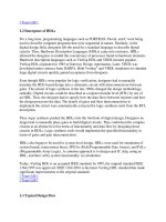
The dummy clock in delay_controls helps in the graphical waveform display
of the results (it provides a one-time-tick timing grid when we zoom in, for exam-
ple). Figure 11.1 shows the graphical output from the Waves viewer in VeriWell
(white is used to represent the initial unknown values). The assignment statements to
'X' in the always statement repeat (every 25 + 10 + 5 = 40 time ticks).
FIGURE 11.1 Output
from the module
delay_controls.
Page 501 Black
October 14, 1997
11.6 TIMING CONTROLS AND DELAY 501
Events can be declared (as named events), triggered, and detected as follows:
module show_event; //1
reg clock; //2
event event_1, event_2; // Declare two named events. //3
always @(posedge clock) -> event_1; // Trigger event_1. //4
always @ event_1 //5
begin $display("Strike 1!!"); -> event_2; end // Trigger event_2. //6
always @ event_2 begin $display("Strike 2!!"); //7
$finish; end // Stop on detection of event_2. //8
always #10 clock = ~ clock; // We need a clock. //9
initial clock = 0; //10
endmodule //11
Strike 1!!
Strike 2!!
11.6.2 Data Slip
Consider this model for a shift register and the simulation output that follows:
module data_slip_1 (); reg Clk, D, Q1, Q2; //1
/************* bad sequential logic below ***************/ //2
always @(posedge Clk) Q1 = D; //3
always @(posedge Clk) Q2 = Q1; // Data slips here! //4
/************* bad sequential logic above ***************/ //5
initial begin Clk = 0; D = 1; end always #50 Clk = ~Clk; //6
initial begin $display("t Clk D Q1 Q2"); //7
$monitor("%3g",$time,,Clk,,,,D,,Q1,,,Q2); end //8
initial #400 $finish; // Run for 8 cycles. //9
initial $dumpvars; //10
endmodule //11
t Clk D Q1 Q2
0 0 1 x x
50 1 1 1 1
100 0 1 1 1
150 1 1 1 1
200 0 1 1 1
250 1 1 1 1
300 0 1 1 1
350 1 1 1 1
The first clock edge at t = 50 causes Q1 to be updated to the value of D at the
clock edge (a '1'), and at the same time Q2 is updated to this new value of Q1. The
data, D, has passed through both always statements. We call this problem data slip.
Page 502 Black
October 14, 1997
502 CHAPTER 11 VERILOG HDL
If we include delays in the always statements (labeled 3 and 4) in the preceding
example, like this—
always @(posedge Clk) Q1 = #1 D; // The delays //3
always @(posedge Clk) Q2 = #1 Q1; // fix data slip. //4
—we obtain the correct output:
t Clk D Q1 Q2
0 0 1 x x
50 1 1 x x
51 1 1 1 x
100 0 1 1 x
150 1 1 1 x
151 1 1 1 1
200 0 1 1 1
250 1 1 1 1
300 0 1 1 1
350 1 1 1 1
11.6.3 Wait Statement
The wait statement suspends a procedure until a condition becomes true. There
must be another concurrent procedure that alters the condition (in this case the vari-
able Done—in general the condition is an expression) in the following wait state-
ment; otherwise we are placed on “infinite hold”:
wait (Done) $stop; // wait until Done = 1 then stop
Notice that the Verilog wait statement does not look for an event or a change in
the condition; instead it is level-sensitive—it only cares that the condition is true.
module test_dff_wait; //1
reg D, Clock, Reset; dff_wait u1(D, Q, Clock, Reset); //2
initial begin D=1; Clock=0;Reset=1'b1; #15 Reset=1'b0; #20 D=0; end //3
always #10 Clock = !Clock; //4
initial begin $display("T Clk D Q Reset"); //5
$monitor("%2g",$time,,Clock,,,,D,,Q,,Reset); #50 $finish; end //6
endmodule //7
module dff_wait(D, Q, Clock, Reset); //1
output Q; input D, Clock, Reset; reg Q; wire D; //2
always @(posedge Clock) if (Reset !== 1) Q = D; //3
always begin wait (Reset == 1) Q = 0; wait (Reset !== 1); end //4
endmodule //5
T Clk D Q Reset
0 0 1 0 1
10 1 1 0 1
15 1 1 0 0
20 0 1 0 0
Page 503 Black
October 14, 1997
11.6 TIMING CONTROLS AND DELAY 503
30 1 1 1 0
35 1 0 1 0
40 0 0 1 0
We must include wait statements in module dff_wait above to wait for both
Reset==1 and Reset==0. If we were to omit the wait statement for Reset==0, as
in the following code:
module dff_wait(D,Q,Clock,Reset); //1
output Q; input D,Clock,Reset; reg Q; wire D; //2
always @(posedge Clock) if (Reset !== 1) Q = D; //3
// We need another wait statement here or we shall spin forever. //4
always begin wait (Reset == 1) Q = 0; end //5
endmodule //6
the simulator would cycle endlessly, and we would need to press the 'Stop' button
or 'CTRL-C' to halt the simulator. Here is the console window in VeriWell:
C1> .
T Clk D Q Reset <- at this point nothing happens, so press CTRL-C
Interrupt at time 0
C1>
11.6.4 Blocking and Nonblocking Assignments
If a procedural assignment in a sequential block contains a timing control, then the
execution of the following statement is delayed or blocked. For this reason a proce-
dural assignment statement is also known as a blocking procedural assignment
statement [Verilog LRM 9.2]. We covered this type of statement in Section 11.5.3.
The nonblocking procedural assignment statement allows execution in a sequen-
tial block to continue and registers are all updated together at the end of the current
time step. Both types of procedural assignment may contain timing controls. Here is
an artificially complicated example that illustrates the different types of assignment:
module delay; //1
reg a,b,c,d,e,f,g,bds,bsd; //2
initial begin //3
a = 1; b = 0; // No delay control. //4
#1 b = 1; // Delayed assignment. //5
c = #1 1; // Intra-assignment delay. //6
#1; // Delay control. //7
d = 1; // //8
e <= #1 1; // Intra-assignment delay, nonblocking assignment //9
#1 f <= 1; // Delayed nonblocking assignment. //10
g <= 1; // Nonblocking assignment. //11
end //12
initial begin #1 bds = b; end // Delay then sample (ds). //13
initial begin bsd = #1 b; end // Sample then delay (sd). //14
initial begin $display("t a b c d e f g bds bsd"); //15